Page 3972 of 4449

POWER STEERING OIL PUMP
PS-39
C
D
E
F
H
I
J
K
L
MA
B
PS
Revision: 2004 November 2004 FX35/FX45
1. Apply a coat of Genuine Nissan PSF or equivalent to oil seal lip
and to the circumference of oil seal. Using proper tool, such as
hand press machine, install it to body assembly.
NOTE:
Do not reuse oil seal.
2. Apply a coat of Genuine Nissan PSF or equivalent to drive shaft
assembly and press drive shaft assembly into body assembly
with suitable tool, then install snap ring.
NOTE:
Do not reuse snap ring.
3. Apply a coat of Genuine Nissan PSF or equivalent to O-ring and
Install O-ring into body assembly.
NOTE:
Do not reuse O-ring.
4. Install side plate to body assembly.
5. Install lock pin into lock pin hole, and install cam-ring as shown
in the figure.
�When installing cam-ring, turn carved face with a letter (E) of
it to rear cover.
CAUTION:
Do not confuse the assembling direction of cam ring. If
cam ring is installed facing the incorrect direction, it may
cause pump operation malfunction.
6. Install rotor to body assembly.
SST038A
SGIA0422E
SGIA0591E
Page 3973 of 4449
PS-40
POWER STEERING OIL PUMP
Revision: 2004 November 2004 FX35/FX45
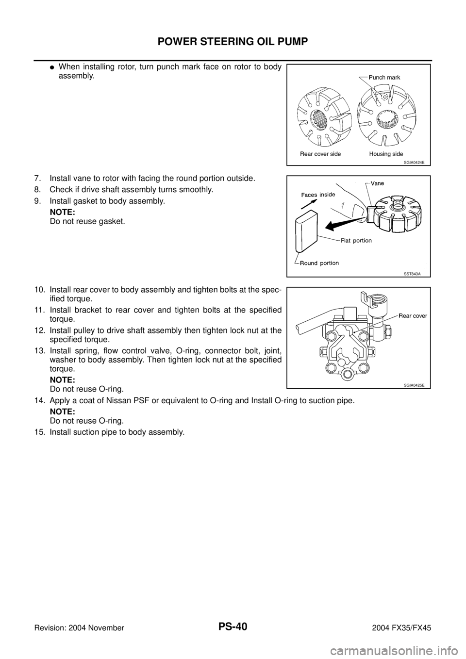
�When installing rotor, turn punch mark face on rotor to body
assembly.
7. Install vane to rotor with facing the round portion outside.
8. Check if drive shaft assembly turns smoothly.
9. Install gasket to body assembly.
NOTE:
Do not reuse gasket.
10. Install rear cover to body assembly and tighten bolts at the spec-
ified torque.
11. Install bracket to rear cover and tighten bolts at the specified
torque.
12. Install pulley to drive shaft assembly then tighten lock nut at the
specified torque.
13. Install spring, flow control valve, O-ring, connector bolt, joint,
washer to body assembly. Then tighten lock nut at the specified
torque.
NOTE:
Do not reuse O-ring.
14. Apply a coat of Nissan PSF or equivalent to O-ring and Install O-ring to suction pipe.
NOTE:
Do not reuse O-ring.
15. Install suction pipe to body assembly.
SGIA0424E
SST843A
SGIA0425E
Page 3976 of 4449
HYDRAULIC LINE
PS-43
C
D
E
F
H
I
J
K
L
MA
B
PS
Revision: 2004 November 2004 FX35/FX45
Removal and InstallationAGS000H6
�Refer to PS-41, "Components" for tightening torque. Install in the reverse order of removal.
NOTE:
Refer to component parts location and do not reuse non-reusable parts.
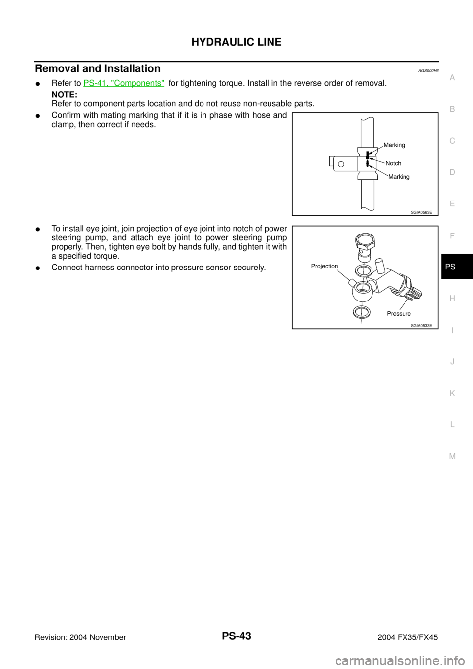
�Confirm with mating marking that if it is in phase with hose and
clamp, then correct if needs.
�To install eye joint, join projection of eye joint into notch of power
steering pump, and attach eye joint to power steering pump
properly. Then, tighten eye bolt by hands fully, and tighten it with
a specified torque.
�Connect harness connector into pressure sensor securely.
SGIA0563E
SGIA0533E
Page 3978 of 4449
HYDRAULIC LINE
PS-45
C
D
E
F
H
I
J
K
L
MA
B
PS
Revision: 2004 November 2004 FX35/FX45
Removal and InstallationAGS000HG
�Refer to PS-41, "Components" for tightening torque. Install in the reverse order of removal.
NOTE:
Refer to component parts location and do not reuse non-reusable parts.
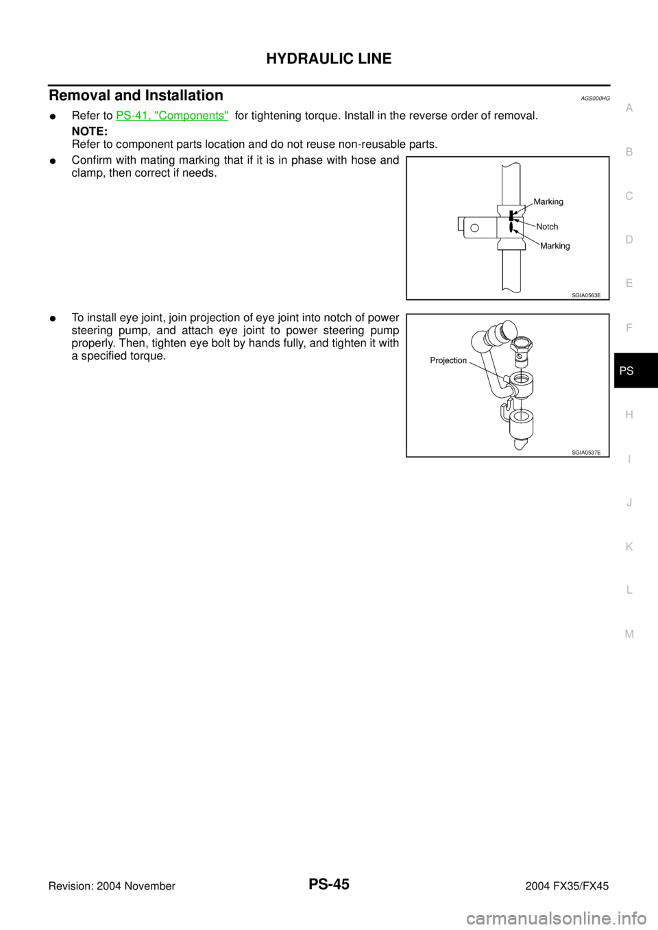
�Confirm with mating marking that if it is in phase with hose and
clamp, then correct if needs.
�To install eye joint, join projection of eye joint into notch of power
steering pump, and attach eye joint to power steering pump
properly. Then, tighten eye bolt by hands fully, and tighten it with
a specified torque.
SGIA0563E
SGIA0537E
Page 3980 of 4449
SERVICE DATA AND SPECIFICATIONS (SDS)
PS-47
C
D
E
F
H
I
J
K
L
MA
B
PS
Revision: 2004 November 2004 FX35/FX45
Steering GearAGS000HB
Oil PumpAGS000HC
Steering FluidAGS000HD
Tie-rod length “L” 135.2 mm (5.32 in)
SGIA0167E
Steering gear modelPR26AM
Rack neutral position, dimension “L” (rack stroke) 67.0 mm (2.638 in)
Rack sliding forceAt the neutral point:
Range within ± 11.5 mm
(±0.453 in) from the neutral
position
(in power ON)Area average value 147 − 211 N (14.99 − 21.52 kg, 33.1 − 47.52 lb)
Allowable variation 98 N (10 kg, 22 lb) or less
Whole area (in power OFF)Peak value 294 N (30.0 kg, 66 lb) or less
Allowable variation 147 N (16 kg, 35 lb) or less
SGIA0629J
Oil pump relief hydraulic pressure
9,900 − 10,700 kPa (101 − 109 kg/cm2 , 1449 − 1564, psi)
Fluid capacity
Approx. 1.0 (1-1/8 US qt, 7/8 Imp qt)
Page 3984 of 4449
ADS000C1
The actual shapes of Kent-Moore tools may differ from those")
PREPARATION
RAX-3
C
E
F
G
H
I
J
K
L
MA
B
RAX
Revision: 2004 November 2004 FX35/FX45
PREPARATIONPFP:00002
Special Service Tools (SST)ADS000C1
The actual shapes of Kent-Moore tools may differ from those of special service tools illustrated here.
Commercial Service ToolsADS000C2
Tool number
(Kent-Moore No.)
Tool nameDescription
ST33251000
( — )
Drift
�Removing wheel hub
�Removing wheel bearing outer side
inner race
�Installing wheel hub
�Inspection of wheel bearing rotating
torque
ST35300000
( — )
Drift
a: 45 mm (1.77 in) dia.
b: 59 mm (2.32 in) dia.
�Installing wheel hub
�Inspection of wheel bearing rotating
torque
KV40100900
( — )
Drift
a: 52 mm (2.05 in) dia.
b: —Wheel bearing rotating torque
inspection
KV38100500
( — )
Drift
a: 80 mm (3.15 in) dia.
b: 60 mm (2.36 in) dia.Installing drive shaft plug
KV38102200
( — )
Drift
a: 90 mm (3.54 in) dia.
b: 31 mm (1.22 in) dia.Installing drive shaft plug
ZZA0982D
ZZA0881D
ZZA0539D
ZZA0701D
ZZA0920D
Tool nameDescription
Power tool
�Removing wheel nuts
�Removing brake caliper assembly
�Removing wheel hub and bearing
assembly
�Removing suspension links
�Removing drive shaft fixing bolts
and nutsPBIC0190E
Page 3986 of 4449
")
WHEEL HUB
RAX-5
C
E
F
G
H
I
J
K
L
MA
B
RAX
Revision: 2004 November 2004 FX35/FX45
WHEEL HUBPFP:43202
On-Vehicle Inspection and ServiceADS000C4
Make sure the mounting conditions (looseness, back lash) of each component and component status (wear,
damage) are normal.
WHEEL BEARING INSPECTION
�Move wheel hub in the axial direction by hand. Make sure there is no looseness of wheel bearing.
�Rotate wheel hub and make sure there is no unusual noise or other irregular conditions. If there are any
irregular conditions, replace wheel bearings.
Removal and InstallationADS000C5
REMOVAL
1. Remove tire with power tool.
2. Remove brake caliper with power tool. Hang it in a place where it will not interfere with work. Refer to BR-
26, "Removal and Installation of Brake Caliper Assembly" .
NOTE:
�Avoid depressing brake pedal while brake caliper is removed.
3. Remove disc rotor.
4. Remove wheel sensor from axle. Refer to BRC-57, "
WHEEL SENSORS" .
CAUTION:
Do not pull on wheel sensor harness.
5. Remove cotter pin. Then remove lock nut from drive shaft.
6. Separate drive shaft from wheel hub and bearing assembly by lightly tapping the end with a suitable ham-
mer and wood block. If it is hard to separate, use a suitable puller.
7. Remove fixing bolts of wheel hub and bearing assembly with power tool, then remove wheel hub and
bearing assembly from axle.
8. Remove parking brake cable and parking brake shoe from back plate. Refer to PB-5, "
PARKING BRAKE
SHOE" and PB-3, "PARKING BRAKE CONTROL" .
9. Remove fixing nuts of anchor block with power tool, then remove anchor block and back plate from axle.Axial end play : 0 mm (0 in)
1. Drive shaft 2. Bushing 3. Axle
4. Back plate 5. Anchor block 6. Wheel bearing
7. Wheel hub 8. Cotter pin
SDIA1481E
Page 3987 of 4449

RAX-6
WHEEL HUB
Revision: 2004 November 2004 FX35/FX45
10. Loosen fixing bolts and nuts of front lower link, radius rod, and rear lower link in side of suspension mem-
ber.
11. Set jack under rear lower link. Then remove fixing bolt in front lower link side of shock absorber with
power tool.
12. Remove bolt and nut in axle side of rear lower link with power tool. Then remove coil spring. Refer to
RSU-15, "
REAR LOWER LINK & COIL SPRING" .
13. Remove fixing bolts and nuts in axle side of front lower link, radius rod with power tool.
14. Remove suspension arm and cotter pin at axle, then loosen mounting nut.
15. Use a ball joint remover (suitable tool) to remove suspension arm from axle. Be careful not to damage ball
joint boot.
CAUTION:
Tighten temporarily mounting nut to prevent damage to threads and to prevent ball joint remover
(suitable tool) from coming off.
16. Remove axle from vehicle.
INSPECTION AFTER REMOVAL
Ball Joint Inspection
Check for boot breakage, axial looseness, and torque of suspension arm ball joint. Refer to RSU-11,
"INSPECTION AFTER REMOVAL" .
INSTALLATION
�Refer to RAX-5, "Removal and Installation" for tightening torque. Install in the reverse order of removal.
NOTE:
Refer to component parts location and do not reuse non-reusable parts.
�Perform final tightening of installation position of suspension links (rubber bushing) under unladen condi-
tions with tires on level ground, Check wheel alignment. Refer to RSU-5, "
Wheel Alignment Inspection" .
�After adjusting wheel alignment, adjust neutral position of steering angle sensor. Refer to BRC-6, "Adjust-
ment of Steering Angle Sensor Neutral Position" .
Disassembly and AssemblyADS000C6
DISASSEMBLY
Wheel Bearing
CAUTION:
Do not disassemble if wheel bearing has no trouble.
1. Remove wheel bearing fixing bolts and anchor block fixing nuts, and remove wheel hub and bearing
assembly, back plate and anchor block from axle.
2. Using a drift (SST) and a puller (suitable tool), press wheel hub
out to remove from wheel bearing.
SDIA1482E

PS-47
C
D
E
F
H
I
J
K
L
MA
B
PS
Revision: 2004 November 2004 FX35/FX45
Steering GearAGS000HB
Oil PumpAGS000HC
Steering FluidAGS000HD
Tie-rod length “L” 135.2")