Page 3939 of 4449
PS-6
PREPARATION
Revision: 2004 November 2004 FX35/FX45
Commercial Service ToolsAGS000GR
1. KV48102500-04
( — )
Washer
2. KV48102500-01
( — )
Eye joint
3. KV48102500-03
( — )
Bolt
4. KV48102500-02
( — )
Flare Joint
5. KV48103500
(J26357&J26357-10)
Pressure gauge & shut off valveMeasuring oil pump relief pressure
(VQ35DE models)
1. KV48105300-4 and 5295262U10
( — )
Connector A and O-ring
2. KV48105300-3 and 5295262U00
( — )
Eye-bolt and O-ring
3. KV48103500
(J26357 and J26357-10)
Pressure gauge and shut-off valve
4. KV48105300-1 and 5295262U00
( — )
Connector B and O-ring
5. KV48105300-2
( — )
NutMeasuring oil pump relief pressure
(VK45DE models) Tool number
(Kent-Moore No.)
Tool nameDescription
SGIA0442E
SGIA0427E
Tool name Description
Power tool
�Removing wheel nuts
�Removing undercover
�Removing steering gear
PBIC0190E
Page 3941 of 4449

PS-8
POWER STEERING FLUID
Revision: 2004 November 2004 FX35/FX45
POWER STEERING FLUIDPFP:KLF20
Checking Fluid LevelAGS000GT
�Stop engine before performing a fluid level check.
�Ensure that fluid level is between the MAX range and MIN level.
�Because fluid level differs within the HOT range and the COLD
range, check it carefully.
CAUTION:
�Do not overfill the Max level.
�Do not reuse any used power steering fluid.
�Recommended fluid is Genuine NISSAN PSF or equivalent.
Checking Fluid LeakageAGS000GU
Check the hydraulic piping lines for improper attachment and for
leaks, cracks, damage, loose connections, chafing or deterioration.
1. Run engine until fluid temperature reaches 50 to 80° C (122 to
176°F) in reservoir tank. Keep engine speed idle.
2. Turn steering wheel right-to-left several times.
3. Hold steering wheel at each “lock” position for five seconds to
check fluid leakage.
CAUTION:
Do not hold steering wheel in a locked position for more
than 10 seconds. (There is the possibility that oil pump may
be damaged.)
4. If fluid leakage at connections is noticed, then loosen flare nut and then retighten. Do not over tighten con-
nector as this can damage O-ring, washer and connector.
5. If fluid leakage from oil pump is noticed, check oil pump. Refer to PS-31, "
POWER STEERING OIL
PUMP" .
6. Check steering gear boots for accumulation of fluid indicating a from steering gear.
Air Bleeding Hydraulic SystemAGS000GV
Incomplete air bleeding causes the following. When this happens, bleed air again.
�Generation of air bubbles in reservoir tank.
�Generation of clicking noise in oil pump.
�Excessive buzzing in oil pump.
NOTE:
When vehicle is stationary or while steering wheel is being turned slowly, some noise may be heard from
oil pump or gear. This noise is normal and does not affect any system.
1. Stop engine, and then turn steering wheel fully to right and left several times.
CAUTION:
Do not allow steering fluid reservoir tank to go below the low-level line. Check tank frequently and
add fluid as needed.
2. Run engine at idle speed. Turn steering wheel fully to the right and then fully to the left, and keep for about
three seconds. Then check whether a fluid leakage has occurred.
3. Repeat the 2nd procedure several times at about three seconds intervals.
CAUTION:
Do not hold steering wheel in the locked position more than 10 seconds. (There is the possibility
that oil pump may be damaged.)
4. Check generation of air bubbles and cloud in fluid.HOT : Fluid temperatures from 50 to 80 °C (122 to
176°F)
COLD : Fluid temperatures from 0 to 30°C (32 to 86°F)
SGIA0232J
SGIA0506E
Page 3942 of 4449
POWER STEERING FLUID
PS-9
C
D
E
F
H
I
J
K
L
MA
B
PS
Revision: 2004 November 2004 FX35/FX45
5. If air bubbles and the cloud don't fade, stop engine, hold air bleeding until air bubbles and the cloud fade.
Perform the 2nd and the 3rd procedures again.
6. Stop engine, check fluid level.
Page 3943 of 4449

PS-10
STEERING WHEEL
Revision: 2004 November 2004 FX35/FX45
STEERING WHEELPFP:48430
On-Vehicle Inspection and ServiceAGS000GW
CHECKING CONDITION OF INSTALLATION
�Check installation condition of steering gear assembly, front suspension, axle and steering column.
�Check if movement exists when steering wheel is moved up and down, to the left and right and to the axial
direction.
�Check if the mounting bolts for steering gear assembly are loose
or not. Refer to PS-19, "
POWER STEERING GEAR AND LINK-
AGE" .
CHECKING STEERING WHEEL PLAY
1. Set tires to the straight ahead, start engine, then turn steering wheel to the left and right lightly, and mea-
sure steering wheel movement on the outer circumference when steering wheel is turned up to the point
where tires start moving.
CHECKING NEUTRAL POSITION ON STEERING WHEEL
Check neutral position on steering wheel after confirming that front wheel alignment is correct. Refer to FSU-
6, "Wheel Alignment Inspection" .
1. Set vehicle to the straight direction, check if steering wheel is in the neutral position.
2. If it is not in the neutral position, remove steering wheel and reinstall it correctly.
3. If the neutral position cannot adjust in the two teeth of steering gear assembly, loosen outer socket lock
nuts of steering outer sockets, then adjust outer socket by the same amount in the opposite direction.
CHECKING STEERING WHEEL TURNING FORCE
1. Park vehicle on a level and dry surface, set parking brake.
2. Remove driver air bag module from steering wheel. Refer to SRS-36, "
DRIVER AIR BAG MODULE" .
3. Start engine at idle, make steering fluid reach to normal operat-
ing temperature [50 to 80°C (122 to 176°F)], then check steering
wheel turning torque with pre-load gauge (SST).
4. If steering wheel turning force is out of the specification, check
relief hydraulic pressure of oil pump. Refer to PS-31, "
POWER
STEERING OIL PUMP" . End play of the axle direction for steering wheel : 0 mm (0 in)
SGIA0546E
Steering wheel play on the outer circumference : 0 − 35 mm (0 − 1.38 in)
Turning torque : 7.45 N·m (0.76 kg-m, 66 in-lb) or less
SGIA0459E
Page 3952 of 4449

POWER STEERING GEAR AND LINKAGE
PS-19
C
D
E
F
H
I
J
K
L
MA
B
PS
Revision: 2004 November 2004 FX35/FX45
POWER STEERING GEAR AND LINKAGEPFP:49001
Removal and InstallationAGS000H0
CAUTION:
Spiral cable may snap due to steering operation if steering column is separated from steering gear
assembly. Therefore fix steering wheel with a string to avoid turns.
REMOVAL
1. Set wheels in the straight-ahead position.
2. Remove tires from vehicle with power tool.
3. Remove undercover with power tool.
4. Confirm slit of lower joint fits with the projection on rear cover
cap, furthermore marking position on steering gear assembly
nearly fits with the projection on rear cover cap.
5. Remove cotter pin at steering outer socket, then loosen mount-
ing nut.
6. Use a ball joint remover (SST) to remove steering outer socket
from steering knuckle. Be careful not to damage ball joint boot.
CAUTION:
Tighten temporarily mounting nut to prevent damage to
threads and to prevent ball joint remover (SST) from com-
ing off.
1. Cotter pin 2. Steering gear assembly 3. Washer
SGIA0538E
SGIA0539E
SDIA1434E
Page 3953 of 4449

from steering gear assembly, then drain fluid from pipings")
PS-20
POWER STEERING GEAR AND LINKAGE
Revision: 2004 November 2004 FX35/FX45
7. Remove oil pipings (high pressure side and low pressure side)
from steering gear assembly, then drain fluid from pipings.
8. Remove mounting bolt of steering hydraulic piping bracket from
steering gear assembly.
9. Remove mounting bolt (lower side) of lower joint.
10. Remove mounting bolts of steering gear assembly with power
tool, and then remove steering gear assembly from vehicle.
INSTALLATION
�Refer to PS-19, "Removal and Installation" for tightening torque. Install in the reverse order of removal.
NOTE:
Refer to component parts location and do not reuse non-reusable parts.
�After removing/installing or replacing steering components, check wheel alignment. Refer to FSU-6,
"Wheel Alignment Inspection" .
�After adjusting wheel alignment, adjust neutral position of steering angle sensor. Refer to BRC-6, "Adjust-
ment of Steering Angle Sensor Neutral Position" .
SGIA0541E
SGIA0545E
SGIA0542E
SGIA0546E
Page 3954 of 4449
POWER STEERING GEAR AND LINKAGE
PS-21
C
D
E
F
H
I
J
K
L
MA
B
PS
Revision: 2004 November 2004 FX35/FX45
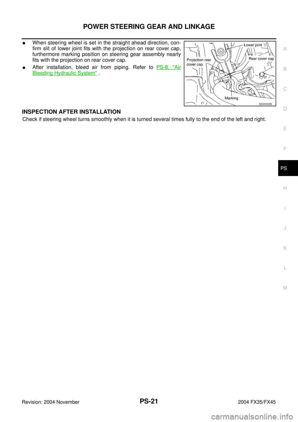
�When steering wheel is set in the straight ahead direction, con-
firm slit of lower joint fits with the projection on rear cover cap,
furthermore marking position on steering gear assembly nearly
fits with the projection on rear cover cap.
�After installation, bleed air from piping. Refer to PS-8, "Air
Bleeding Hydraulic System" .
INSPECTION AFTER INSTALLATION
Check if steering wheel turns smoothly when it is turned several times fully to the end of the left and right.
SGIA0539E
Page 3955 of 4449
PS-22
POWER STEERING GEAR AND LINKAGE
Revision: 2004 November 2004 FX35/FX45
Disassembly and AssemblyAGS000H1
SGIA0543E

Washer
2. KV48102500-01
( — )
Eye joint
3")