Page 4015 of 4449

RF-18
SUNROOF
Revision: 2004 November 2004 FX35/FX45
Trouble Diagnosis Chart by SymptomAIS003D0
Power Supply and Ground Circuit Check of BCMAIS003D1
1. CHECK FUSE
�Check 15A fuse [No.1, located in fuse block (J/B)]
�Check 15A fuse [No.22, located in fuse block (J/B)]
�Check 50A fusible link (letter M located in the fuse and fusible link box).
NOTE:
Refer to RF-10, "
Component Parts and Harness Connector Location" .
OK or NG
OK >> GO TO 2.
NG >> If fuse is blown out, be sure to eliminate cause of malfunction before installing new fuse. Refer to
PG-3, "
POWER SUPPLY ROUTING CIRCUIT" .
2. CHECK POWER SUPPLY CIRCUIT
1. Turn ignition switch ON.
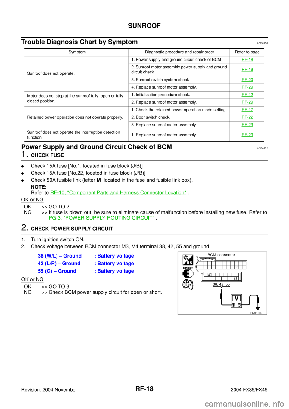
2. Check voltage between BCM connector M3, M4 terminal 38, 42, 55 and ground.
OK or NG
OK >> GO TO 3.
NG >> Check BCM power supply circuit for open or short.
Symptom Diagnostic procedure and repair order Refer to page
Sunroof does not operate.1. Power supply and ground circuit check of BCMRF-18
2. Sunroof motor assembly power supply and ground
circuit checkRF-19
3. Sunroof switch system checkRF-20
4. Replace sunroof motor assembly.RF-29
Motor does not stop at the sunroof fully -open or fully-
closed position.1. Initialization procedure check.RF-12
2. Replace sunroof motor assembly.RF-29
Retained power operation does not operate properly.1. Check the retained power operation mode setting.RF-172. Door switch check.RF-22
3. Replace sunroof motor assembly.RF-29
Sunroof does not operate the interruption detection
function.1. Replace sunroof motor assembly.RF-29
38 (W/L) – Ground : Battery voltage
42 (L/R) – Ground : Battery voltage
55 (G) – Ground : Battery voltage
PIIA6160E
Page 4099 of 4449

SC-10
STARTING SYSTEM
Revision: 2004 November 2004 FX35/FX45
STARTING SYSTEMPFP:23300
System Description AKS0079C
Power is supplied at all times:
�through 40A fusible link (letter F, located in the fuse and fusible link box)
�to ignition switch terminal 1
�through 15A fuse (No. 78, located in the IPDM E/R)
�to CPU of IPDM E/R
�through 10A fuse (No. 71, located in the IPDM E/R)
�to CPU of IPDM E/R.
When the selector lever in the P or N position, power is supplied:
�from TCM, and through A/T assembly terminal 9
�to IPDM E/R terminal 53.
Ground is supplied:
�to IPDM E/R terminals 38, 50 and 60
�from body grounds E21, E50 and E51.
With the ignition switch in the START position, and provided that the IPDM E/R receives a starter relay ON sig-
nal from the CAN lines, the IPDM E/R is energized and power is supplied:
�from ignition switch terminal 5
�to IPDM E/R terminal 4 and
�through IPDM E/R terminal 3
�to starter motor terminal 1.
The starter motor plunger closes and provides a closed circuit between the battery and starter motor. The
starter motor is grounded to the engine block. With power and ground supplied, cranking occurs and the
engine starts.
Page 4112 of 4449

CHARGING SYSTEM
SC-23
C
D
E
F
G
H
I
J
L
MA
B
SC
Revision: 2004 November 2004 FX35/FX45
CHARGING SYSTEMPFP:23100
System DescriptionAKS0079I
The alternator provides DC voltage to operate the vehicle's electrical system and to keep the battery charged.
The voltage output is controlled by the IC regulator.
Power is supplied at all times:
�through 10A fuse (No. 33, located in the fuse and fusible link box)
�to alternator terminal 4 (S).
Terminal B supplies power to charge the battery and operate the vehicle's electrical system. Output voltage is
controlled by the IC regulator at terminal 4 (S) detecting the input voltage.
The charging circuit is protected by the 120A fusible link (VK45DE and VQ35DE AWD).
The alternator is grounded to the engine block.
With the ignition switch in the ON or START position, power is supplied:
�through 10A fuse [No. 14, located in the fuse block (J/B)]
�to combination meter terminal 7 for the charge warning lamp.
Ground is supplied:
�to combination meter terminal 2
�through alternator terminal 3 (L)
�to alternator terminal E (VK45DE) or through body ground (VQ35DE)
�through body ground E304 (VK45DE).
With power and ground supplied, the charge warning lamp will illuminate. When the alternator is providing suf-
ficient voltage with the engine running, the ground is opened and the charge warning lamp will go off.
If the charge warning lamp illuminates with the engine running, a malfunction is indicated.
Page 4118 of 4449
CHARGING SYSTEM
SC-29
C
D
E
F
G
H
I
J
L
MA
B
SC
Revision: 2004 November 2004 FX35/FX45
DIAGNOSTIC PROCEDURE 1
Check “L” Terminal Circuit
1. CHECK “L” TERMINAL CONNECTION
1. Turn ignition switch OFF.
2. Check to see if “L” terminal is clean and tight.
OK or NG
OK >> GO TO 2.
NG >> Repair “L” terminal connection. Confirm repair by performing complete Battery/Starting/Charging
system test.
2. CHECK “L” TERMINAL CIRCUIT
1. Disconnect alternator connector.
2. Apply ground to alternator harness connector E311
*1 or F26*2
terminal 3 (OR) with the ignition switch in the ON position.
NOTE:
*1: VK45DE, *2: VQ35DE
OK or NG
OK >> Go to SC-28, "WORK FLOW" .
NG >> Check the following.
�10A fuse [No. 14, located in fuse block (J/B)]
�CHARGE lamp
�Harness for open or short between combination meter and fuse
�Harness for open or short between combination meter and alternator CHARGE lamp should light up.
PKIA2815E
Page 4120 of 4449
CHARGING SYSTEM
SC-31
C
D
E
F
G
H
I
J
L
MA
B
SC
Revision: 2004 November 2004 FX35/FX45
DIAGNOSTIC PROCEDURE 3
Check “L” Terminal Circuit
1. CHECK “L” TERMINAL CONNECTION
1. Turn ignition switch OFF.
2. Check to see if “L” terminal is clean and tight.
OK or NG
OK >> GO TO 2.
NG >> Repair “L” terminal connection. Confirm repair by performing complete Battery/Starting/Charging
system test.
2. CHECK “L” TERMINAL CIRCUIT
1. Disconnect alternator connector.
2. Apply ground to alternator harness connector E311
*1 or F26*2
terminal 3 (OR) with the ignition switch in the ON position.
NOTE:
*1: VK45DE, *2: VQ35DE
OK or NG
OK >> Replace the alternator. Confirm repair by performing
complete Battery/Starting/Charging system test.
NG >> Check the following.
�10A fuse [No. 14, located in fuse block (J/B)]
�CHARGE lamp
�Harness for open or short between combination meter and fuse
�Harness for open or short between combination meter and alternator CHARGE lamp should light up.
PKIA2815E
Page 4165 of 4449

SE-36
AUTOMATIC DRIVE POSITIONER
Revision: 2004 November 2004 FX35/FX45
2. CHECK POWER SUPPLY CIRCUIT (BCM)
1. Turn ignition switch OFF.
2. Disconnect BCM connector.
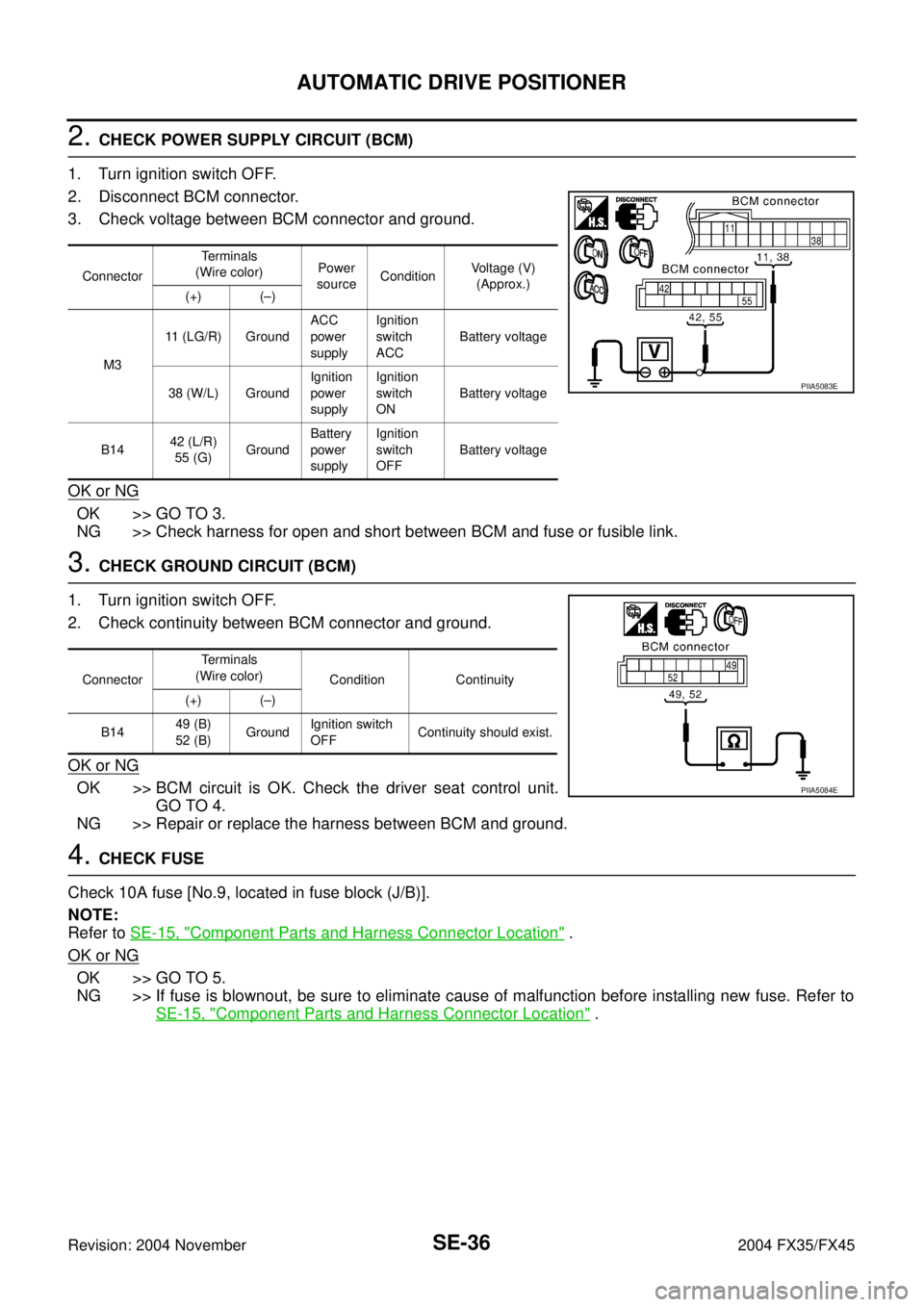
3. Check voltage between BCM connector and ground.
OK or NG
OK >> GO TO 3.
NG >> Check harness for open and short between BCM and fuse or fusible link.
3. CHECK GROUND CIRCUIT (BCM)
1. Turn ignition switch OFF.
2. Check continuity between BCM connector and ground.
OK or NG
OK >> BCM circuit is OK. Check the driver seat control unit.
GO TO 4.
NG >> Repair or replace the harness between BCM and ground.
4. CHECK FUSE
Check 10A fuse [No.9, located in fuse block (J/B)].
NOTE:
Refer to SE-15, "
Component Parts and Harness Connector Location" .
OK or NG
OK >> GO TO 5.
NG >> If fuse is blownout, be sure to eliminate cause of malfunction before installing new fuse. Refer to
SE-15, "
Component Parts and Harness Connector Location" .
ConnectorTe r m i n a l s
(Wire color)Power
sourceConditionVoltage (V)
(Approx.)
(+) (–)
M311 (LG/R) GroundACC
power
supplyIgnition
switch
ACCBattery voltage
38 (W/L) GroundIgnition
power
supplyIgnition
switch
ONBattery voltage
B1442 (L/R)
55 (G)GroundBattery
power
supplyIgnition
switch
OFFBattery voltage
PIIA5083E
ConnectorTe r m i n a l s
(Wire color)
Condition Continuity
(+) (–)
B1449 (B)
52 (B)GroundIgnition switch
OFFContinuity should exist.
PIIA5084E
Page 4166 of 4449

AUTOMATIC DRIVE POSITIONER
SE-37
C
D
E
F
G
H
J
K
L
MA
B
SE
Revision: 2004 November 2004 FX35/FX45
5. CHECK POWER SUPPLY CIRCUIT (DRIVER SEAT CONTROL UNIT)
1. Disconnect driver seat control unit connector.
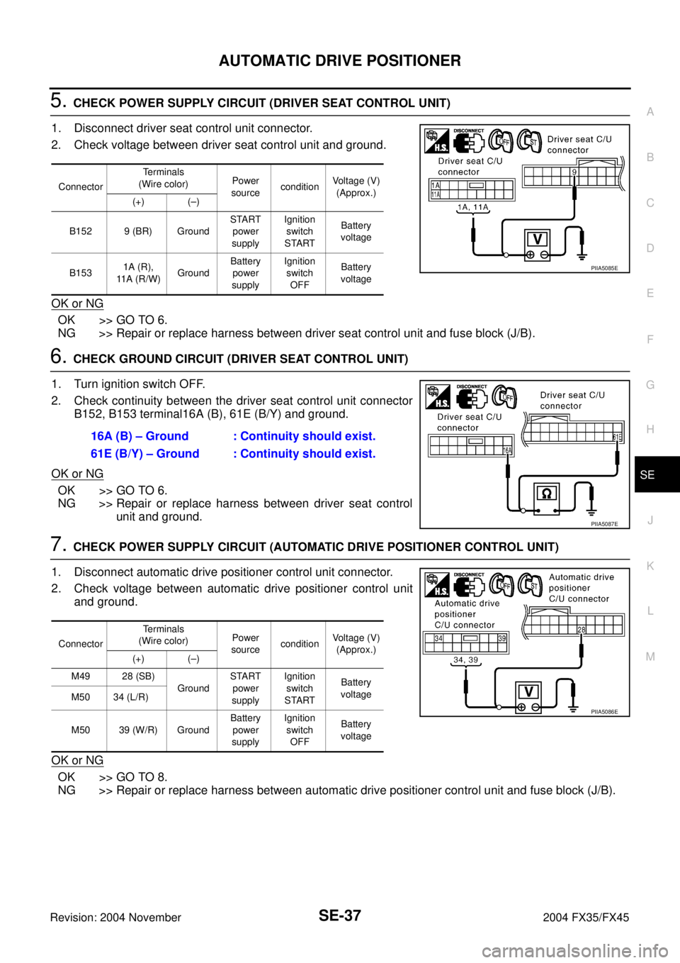
2. Check voltage between driver seat control unit and ground.
OK or NG
OK >> GO TO 6.
NG >> Repair or replace harness between driver seat control unit and fuse block (J/B).
6. CHECK GROUND CIRCUIT (DRIVER SEAT CONTROL UNIT)
1. Turn ignition switch OFF.
2. Check continuity between the driver seat control unit connector
B152, B153 terminal16A (B), 61E (B/Y) and ground.
OK or NG
OK >> GO TO 6.
NG >> Repair or replace harness between driver seat control
unit and ground.
7. CHECK POWER SUPPLY CIRCUIT (AUTOMATIC DRIVE POSITIONER CONTROL UNIT)
1. Disconnect automatic drive positioner control unit connector.
2. Check voltage between automatic drive positioner control unit
and ground.
OK or NG
OK >> GO TO 8.
NG >> Repair or replace harness between automatic drive positioner control unit and fuse block (J/B).
ConnectorTerminals
(Wire color)Power
sourceconditionVoltage (V)
(Approx.)
(+) (–)
B152 9 (BR) GroundSTART
power
supplyIgnition
switch
STARTBattery
voltage
B1531A (R),
11 A ( R / W )GroundBattery
power
supplyIgnition
switch
OFFBattery
voltage
PIIA5085E
16A (B) – Ground : Continuity should exist.
61E (B/Y) – Ground : Continuity should exist.
PIIA5087E
ConnectorTerminals
(Wire color)Power
sourceconditionVoltage (V)
(Approx.)
(+) (–)
M49 28 (SB)
GroundSTART
power
supplyIgnition
switch
STARTBattery
voltage
M50 34 (L/R)
M50 39 (W/R) GroundBattery
power
supplyIgnition
switch
OFFBattery
voltage
PIIA5086E
Page 4217 of 4449

SE-88
AUTOMATIC DRIVE POSITIONER
Revision: 2004 November 2004 FX35/FX45
4. CHECK "MEMORY SWITCH AND LUMBER SUPPORT SWITCH" GROUND CIRCUIT
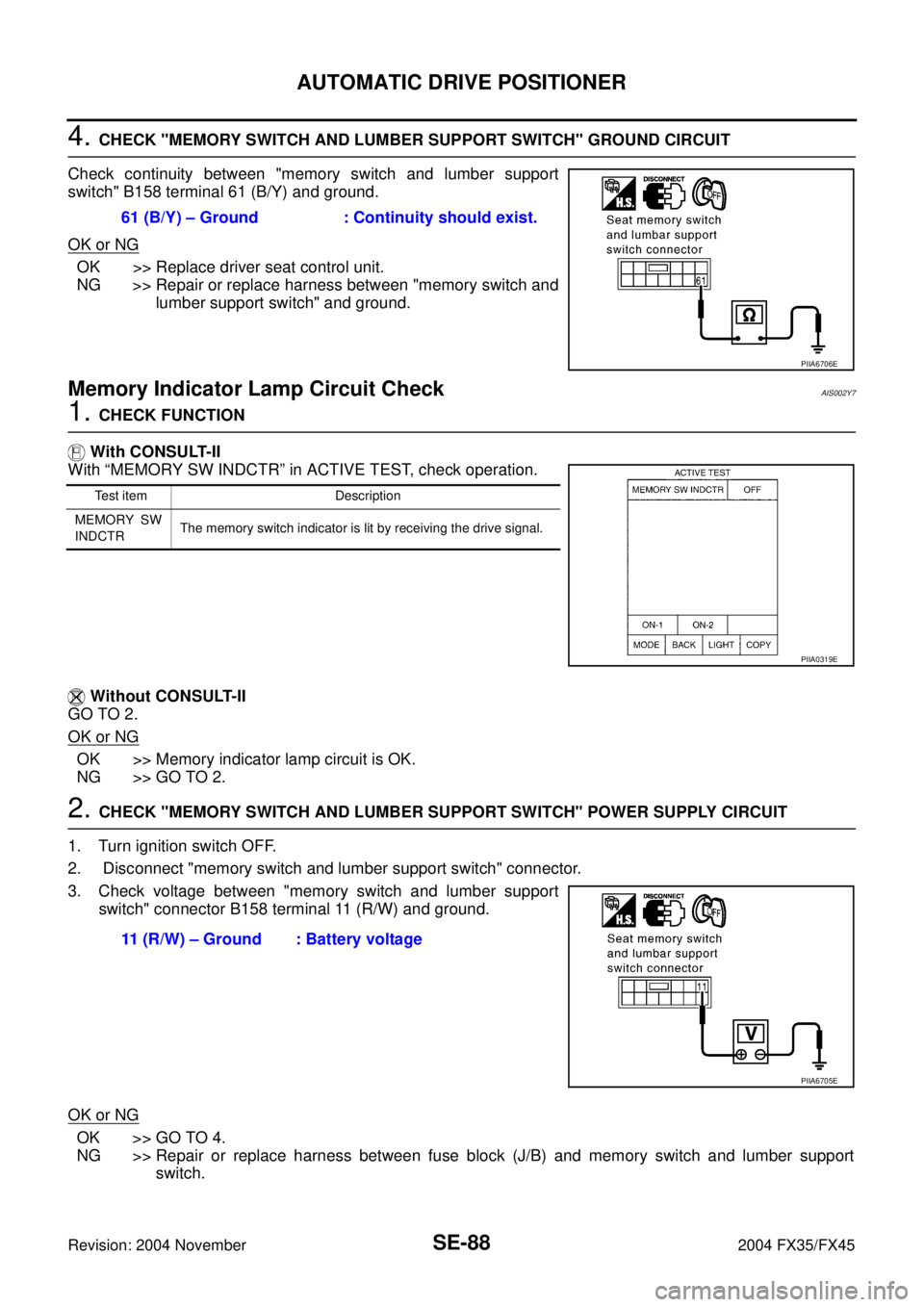
Check continuity between "memory switch and lumber support
switch" B158 terminal 61 (B/Y) and ground.
OK or NG
OK >> Replace driver seat control unit.
NG >> Repair or replace harness between "memory switch and
lumber support switch" and ground.
Memory Indicator Lamp Circuit CheckAIS002Y7
1. CHECK FUNCTION
With CONSULT-II
With “MEMORY SW INDCTR” in ACTIVE TEST, check operation.
Without CONSULT-II
GO TO 2.
OK or NG
OK >> Memory indicator lamp circuit is OK.
NG >> GO TO 2.
2. CHECK "MEMORY SWITCH AND LUMBER SUPPORT SWITCH" POWER SUPPLY CIRCUIT
1. Turn ignition switch OFF.
2. Disconnect "memory switch and lumber support switch" connector.
3. Check voltage between "memory switch and lumber support
switch" connector B158 terminal 11 (R/W) and ground.
OK or NG
OK >> GO TO 4.
NG >> Repair or replace harness between fuse block (J/B) and memory switch and lumber support
switch. 61 (B/Y) – Ground : Continuity should exist.
PIIA6706E
Test item Description
MEMORY SW
INDCTRThe memory switch indicator is lit by receiving the drive signal.
PIIA0319E
11 (R/W) – Ground : Battery voltage
PIIA6705E