2004 Hyundai Coupe parking brake
[x] Cancel search: parking brakePage 163 of 389

VEHICLE SPECIFICATIONS 9-1
J030A01GK-GAT TIRE
1.6L
MF 60AH 90A
Dual hydraulic with brake booster Ventilated discSolid discCable
9. VEHICLE SPECIFICATIONS
J010A01GK-GAT MEASUREMENT
J060A01F-AAT FUEL SYSTEM
Type Wheel free playRack strokeOil pump type Rack and pinion0 ~ 30 mm (0 ~ 1.18 in.)132 mm (5.20 in.)Vane type
195/65 R15 205/55 R16, 215/45 R17
StandardOption
Overall length Overall widthOverall height (unladen)Wheel base
Front Rear
4395(173)
1760(69.3) 1330(52.4)2530(99.6)1490(58.7)1490(58.7)
Wheel tread mm (in.)
J020A01GK-GAT POWER STEERING
Fuel tank capacity Liter
55 US.gal
14.5 Imp.gal
12
J040A02GK-GAT ELECTRICAL
Item BatteryAlternator
J050A01GK-GAT BRAKE Type Front brake typeRear brake typeParking brake
J035A01GK-GAT SPARE TIRE
T125/70 R16 (Temporary)
Standard
2.0L
MF 68AH 90A2.7L
MF 68AH 95A
9
Page 168 of 389

INDEX10-3
R Rear Seats
Before Folding the Rear Seats ..................................................... 1-10
Fold down ..................................................................................... 1-10
Rear seat entry ............................................................................. 1-10
Rear Seat Pos itions ....................................................................... 1-9
Rear Window Defroster Switch ......................................................... 1-36
Rear Window Wiper and Switch .. ..................................................... 1-35
SSeat Belts 3-Point type .................................................................................. 1-13
Adjustable height .......................................................................... 1-13
Adjusting your seat belt ................................................................ 1-13
Care of seat belts ......................................................................... 1-12
Precautions ................................................................................... 1-11
Pre-tentioner Seat Belt ................................................................. 1-18
Spark Plugs ........................................................................................ 6-8
Spectacle Case ................................................................................. 1-40
Speedometer ..................................................................................... 1-30
Starting Procedures ............................................................................ 2-3Steering Wheel Free play ...................................................................................... 6-15
Tilt lever ........................................................................................ 1-47
Stereo Radio Operation (H250, H260) ....................................1-65, 1-72
Stereo Sound System ............................................................ 1-63 ~ 1-64Sun Visor .......................................................................................... 1-46
Sunroof .............................................................................................. 1-38
TTachometer ....................................................................................... 1-30
Tail Gate ........................................................................................... 1-45
TCS (Traction control system) .......................................................... 2-10
Theft Alarm System ............................................................................ 1-5
JJump Starting
...................................................................................... 3-1
K
Keys .................................................................................................. 1-2 If you lose your keys .................................................................... 3-10
Positions ......................................................................................... 2-2
L
Light Bulb Replacement .................................................................... 6-20
Lubrication Chart ................................................................................. 9-3
Luggage Net ...................................................................................... 1-47
M Maintenance Intervals Explanation of scheduled maintenance items ....................... 5-5 ~ 5-7
Maintenance under severe usage conditions ................................. 5-4
Scheduled maintenance ................................................................. 5-2
Service requirements ...................................................................... 5-1
Map Light .......................................................................................... 1-40
Mirros Day-night inside rearview ............................................................. 1-42
Outside rearview folding ............................................................... 1-42
Outsde rearview heating .............................................................. 1-41
Multi gauge ........................................................................................ 1-32
OOdometer .......................................................................................... 1-30
PParking Brake ................................................................................... 1-43
Power Steering Fluid Level ............................................................... 6-19
Page 179 of 389

CAUTION:
When installing a container of liquid air freshener inside the vehicle, do not place it near the instrument cluster nor on the instrument panel surface. If there is any leakage from the air freshener onto these areas (Instrument cluster, instrument panel or air ventilator), it may damage these parts. If the liquid from the air freshener does leak onto these areas, wash themwith water immediately.!
1. Passenger's Drink Holder
2. Passenger's Side Air Bag (Not all models)
3. Multi Guage (Not all models)
4. Front Fog Light Switch (Not all models)
5. Rear Fog Light Switch
6. Digital Clock
7. Hazard Warning Switch
8. Front Seat warmer (Not all models)
9. Windscreen Wiper/Washer Switch
10. Steering Wheel Tilt Lever (Not all models)
11. Multi-Function Light
12. Panel Brightness Control Knob
(Rheostat Switch) (Not all models) 13. Electronic Stability Progrem (ESP) Switch
(Not all models)
14. Headlight Leveling Device
15. Centre Console
16. Glove Box
17. Parking Brake Lever
18. Shift Lever
19. Cigarette Lighter
20. Ashtray
21. Heating/Air Conditioning Control Panel
22. Horn and Driver's Airbag
23. Cruise Control Switch (Not all models)
24. Fuse Box Relay
25. Bonnet Release Lever
Page 180 of 389

YOUR VEHICLE AT A GLANCE
B255A01GK-EAT INDICATOR SYMBOLS ON THE INSTRUMENT PANEL * More detailed explanations of these items will be found beginning on page 1-40.
Malfunction Indicator Light (Not all models)
SRS (Airbag) Service Reminder Indicator (SRI)(Not all models)
Hatchback Door Open Warning Light
Low Fuel Level Warning Light
Door Ajar Warning Light (Not all models)
ABS Service Reminder Indicator (Not all models)
Turn Signal Indicator Lights
High Beam Indicator Light Low Oil Pressure Warning Light Parking Brake/Brake Fluid Level Warning Light Charging System Warning Light
Cruise Indicator (Not all models)
Seat Belt Warning Light
CRUISE SET Indicator Light (Not all models)
Electronic Stability Program (ESP) Indicator Light (Not all models)
Immobiliser Warning Light
Page 219 of 389

1
CONTROLS AND EQUIPMENT
39
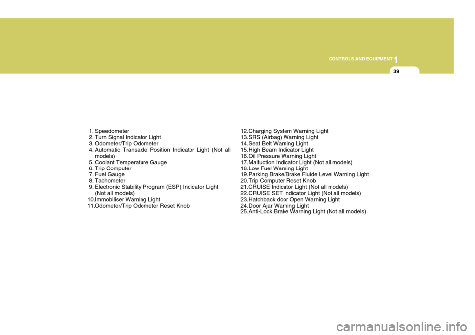
1. Speedometer
2. Turn Signal Indicator Light
3. Odometer/Trip Odometer
4. Automatic Transaxle Position Indicator Light (Not all models)
5. Coolant Temperature Gauge
6. Trip Computer
7. Fuel Gauge
8. Tachometer
9. Electronic Stability Program (ESP) Indicator Light (Not all models)
10.Immobiliser Warning Light
11.Odometer/Trip Odometer Reset Knob 12.Charging System Warning Light
13.SRS (Airbag) Warning Light
14.Seat Belt Warning Light
15.High Beam Indicator Light
16.Oil Pressure Warning Light
17.Malfuction Indicator Light (Not all models)
18.Low Fuel Warning Light
19.Parking Brake/Brake Fluide Level Warning Light
20.Trip Computer Reset Knob21.CRUISE Indicator Light (Not all models)
22.CRUISE SET Indicator Light (Not all models)
23.Hatchback door Open Warning Light
24.Door Ajar Warning Light
25.Anti-Lock Brake Warning Light (Not all models)
Page 220 of 389

1CONTROLS AND EQUIPMENT
40
!
!
WARNING AND INDICATOR LIGHTS
SB210K1-ELOW OIL PRESSURE WARN ING LAMP
SB210G1-ETURN SIGNAL INDICA- TOR LAMPS
Operation of a turn signal is indicated by the warning lamp located in theinstrument cluster. If the lamp fails to illuminate or does not flash, a malfunc- tion within the turn signal system isindicated. 260P02Y-EAT ABS Service Reminder Indicator (Not all models)
When the key is turned to the "ON" position, the Anti-Lock Brake System SRI will come on and then go off in afew seconds. If the ABS SRI remains on, comes on while driving, or does not come on when the key is turned to the"ON" position, this indicates that there may be a problem with the ABS. If this occurs, have your vehiclechecked by your Hyundai dealer as soon as possible. The normal braking system will still be operational, butwithout the assistance of the anti-lock brake system. WARNING:
If the both ABS SRI and ParkingBrake/Brake fluid level warning lights remain "ON" or come on whiledriving, there may be a problem with E.B.D (Electronic brake force distribution).If this occurs, avoid sudden stops and have your vehicle checked by your Hyundai dealer as soon aspossible.SB210J1-E HIGH BEAM INDICATOR LAMP
The high beam indicator lamp will illu- minate whenever the headlamps areswitched to high beam of flash posi- tion.
CAUTION:
If the oil pressure warning light illuminates when the engine is run- ning, an insufficient oil pressure level for continued safe operationof the engine exists. Continued operation of the engine in this con- dition may result in serious enginedamage. Under normal circumstances, the light will illuminate when the igni- tion is turned "on" and will be extin- guished when the engine is started.
Page 221 of 389

1
CONTROLS AND EQUIPMENT
41
!
If the oil pressure warning light illuminates whilst the engine is run- ning, stop the engine immediately and check the engine oil level. If thelevel is insufficient, add the required amount of oil as indicated by the engine oil dipstick. If the light failsto extinguish when the engine is restarted, do not continue to oper- ate the vehicle.If the oil pressure light illuminates during normal operation and the cause is not an insufficient oil level,or the light fails to illuminate when the ignition is turned "on", contact the nearest Hyundai dealer beforefurther operating the vehicle. B260H01GK-EAT
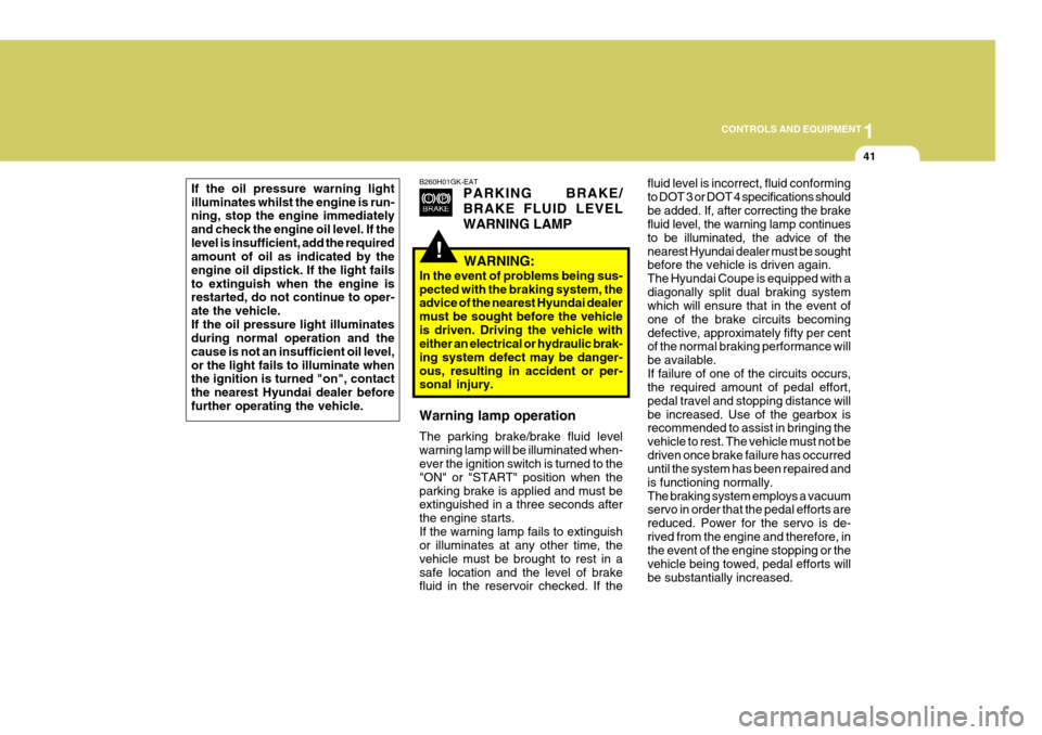
PARKING BRAKE/ BRAKE FLUID LEVELWARNING LAMP
WARNING:
In the event of problems being sus- pected with the braking system, the advice of the nearest Hyundai dealer must be sought before the vehicleis driven. Driving the vehicle with either an electrical or hydraulic brak- ing system defect may be danger-ous, resulting in accident or per- sonal injury. Warning lamp operation The parking brake/brake fluid level warning lamp will be illuminated when- ever the ignition switch is turned to the "ON" or "START" position when theparking brake is applied and must be extinguished in a three seconds after the engine starts.If the warning lamp fails to extinguish or illuminates at any other time, the vehicle must be brought to rest in asafe location and the level of brake fluid in the reservoir checked. If the fluid level is incorrect, fluid conforming to DOT 3 or DOT 4 specifications shouldbe added. If, after correcting the brake fluid level, the warning lamp continues to be illuminated, the advice of thenearest Hyundai dealer must be sought
before the vehicle is driven again. The Hyundai Coupe is equipped with adiagonally split dual braking system which will ensure that in the event of one of the brake circuits becomingdefective, approximately fifty per cent of the normal braking performance will be available.If failure of one of the circuits occurs, the required amount of pedal effort, pedal travel and stopping distance willbe increased. Use of the gearbox is recommended to assist in bringing the vehicle to rest. The vehicle must not bedriven once brake failure has occurred until the system has been repaired and is functioning normally.The braking system employs a vacuum servo in order that the pedal efforts are reduced. Power for the servo is de-rived from the engine and therefore, in the event of the engine stopping or the vehicle being towed, pedal efforts willbe substantially increased.
Page 244 of 389

1CONTROLS AND EQUIPMENT
64HIGH-MOUNTED REAR STOP LIGHT
B550A02S-DAT In addition to the lower-mounted rear stopl ights on either side of the car, thehigh mounted rear stop light in the centre of the rear window or inserted in the rear spoiler also comes on whenthe brakes are applied. Type A
B550A01GK
Type B Type C
PARKING BRAKE
SB380A1-E The parking brake must always be set when the vehicle is to be left unattended.When the parking brake is applied, and the ignition key is at the "ON" position, the parking brake warning lamp will beilluminated. Before driving the vehicle, the parking brake must be fully released and the warning lamp extinguished.
o To set the parking brake, apply the foot brake and pull the parking brake lever up with the button depressed. Release the button when the brake is fully applied.
o To release the parking brake, apply the foot brake and pull up the park-ing brake lever slightly. Depress thebutton and lower the lever. HGK3019
B520B01O-GAT (Electric type) (Not all models) The electric type day/night inside rear- view mirror automatically controls the glare of headlights of the car behindyou. Adjust the rearview mirror to the desired position.
Sensor
HGK2051