2004 Hyundai Coupe tyre pressure
[x] Cancel search: tyre pressurePage 281 of 389
2
DRIVING YOUR HYUNDAI
5
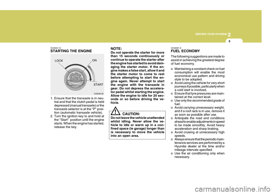
SC060A1-E STARTING THE ENGINE
LOCK SC060B1-EFUEL ECONOMY The following suggestions are made to assist in achieving the greatest degreeof fuel economy.
o Maintaining a constant check on fuel
consumption will enable the most economical use pattern and drivingstyle to be adopted.
o Avoid using the vehicle for very short journeys if possible, particularly whena cold start is involved.
o Ensure that tyre pressures are main- tained at the correct level.
o Use only the recommended grade of fuel.
o Avoid carrying unnecessary weight, and if a roof rack is in use, remove itas soon as possible after use.
o Anticipate the road and conditions ahead to enable adjustments in speedto be made smoothly. Avoid heavyacceleration and sharp braking.
o Avoid cruising at unnecessary high speeds.
o Always ensure that the periodic main- tenance services are performed by aHyundai dealer at the time and/ormileage intervals specified.
o Use the air conditioning only when necessary.
C050A01E
ON
START NOTE: Do not operate the starter for more than 15 seconds continuously or continue to operate the starter afterthe engine has started to avoid dam- aging the starter motor. If the en- gine makes a false start, allow it andthe starter motor to come to rest before attempting to start the en- gine again. Never attempt to startthe engine with the transaxle in gear. Do not depress the accelera- tor pedal whilst starting the engine.Allow the engine to idle for 20 sec- onds or so before driving the ve- hicle.
1. Ensure that the transaxle is in neu-
tral and that the clutch pedal is helddepressed (manual transaxle) or thetransaxle selector is at the "P" posi- tion (automatic transaxle vehicle).
2. Turn the ignition key to and hold at the "Start" position until the enginestarts. When the engine has started, release the key. CAUTION:
Do not leave the vehicle unattendedwhilst idling. Never allow the ve-hicle to idle or warm up in a con- fined space (ie garage) longer than is necessary to move the vehicleinto an open area.
!
Page 288 of 389

2DRIVING YOUR HYUNDAI
12
WARNING:
ABS will not prevent accidents due to improper or dangerous driving manoeuvres. Even though vehiclecontrol is improved during emer- gency braking, always maintain a safe distance between you and ob-jects ahead. Vehicle speeds should always be reduced during extreme road conditions.The braking distance for cars equipped with an anti-lock braking system may be longer than for thosewithout it in the following road con- ditions. These roads should be driven at reduced speeds.
o Rough, gravel or snow-covered roads.
o With tyre chains installed.
o On roads where the road surface
is pitted or has different surface height.!The safety features of an ABS equipped vehicle should not be tested by high speed driving or cornering. This could endanger thesafety of yourself or others.
ANTI-LOCK BRAKE SYSTEM (ABS)
C120A02A-EAT (Not all models) The Anti-Lock Brake System (ABS) is designed to prevent wheel lock-up during sudden braking or on hazard- ous road surfaces. The ABS controlmodule monitors the wheel speed and controls the pressure applied to each brake. Thus, in emergency situationsor on slick roads, ABS will increase vehicle control during braking. NOTE: During ABS operation, a slight pul- sation may be felt in the brake pedal when the brakes are applied. Also,a noise may be heard in the engine compartment while braking. These conditions are normal and indicatethat the anti-lock brake system is functioning properly.
Page 303 of 389
3
IN CASE OF EMERGENCY
5
!
!WARNING:
Whilst the engine is running, keep hands and clothing away from mov- ing parts such as the fan and drive belts to prevent injury.
5. If the water pump drive belt is bro- ken or coolant is leaking out, stop the engine immediately and call the nearest Hyundai dealer for assis-tance.
WARNING:
Do not remove the radiator cap when the engine is hot since steam and boiling water may be ejected fromthe radiator resulting in burns or scalding.
!
6. If the cause of the overheating can- not be found, wait until the engine temperature has returned to nor- mal. Then, if coolant has been lost, carefully add coolant to the reser-voir (page 6-11) to bring the fluid level in the reservoir up to the base of the radiator fill opening. Fill thecoolant expansion tank to the half- way mark.
7. Proceed with caution until it is es- tablished that the engine is operat-ing normally. If the engine over- heats repeatedly, the advice of aHyundai dealer should be sought.
CAUTION:
Serious loss of coolant indicatesthere is a leak in the cooling systemand this should be checked as soon as possible by a Hyundai dealer.D040A01GK-EAT TEMPORARY SPARE TYRE The following instructions for the tem- porary spare tyre should be observed:
1. Check inflation pressure as soon as practical after installing the spare tyre, and adjust to the specified pressure. The tyre pressure should be periodically checked and main-tained at the specified pressure while the tyre is stored.
2. The spare tyre should only be used temporarily and should be returnedto the luggage compartment as soon as the original tyre can be repairedor replaced.
SPARE TYRE
Tyre Size
Inflation Pressure T125/70 R16
420 kPa (60 psi)
Spare Tyre Pressure
3. Continuous use at speeds of over 50 mph (80 km/h) is not recom- mended.
4. As the temporary spare tyre is spe-
cifically designed for your car, itshould not be used on any other vehicle.
Page 304 of 389

3 IN CASE OF EMERGENCY
6IN THE EVENT OF A PUNC- TURE
SD070A1-ECHANGING A FLAT TYRE
It is of the utmost importance that care is exercised when changing road wheels. Ensure that the parking brakeis set and that the gear shift lever is in reverse (P, if the vehicle has automatic transaxle).
D060A01GK
! CAUTION:
o Do not use snow chains with your temporary spare tyre.
o Do not use more than one tempo-
rary spare tyre at a time.
5. The temporary spare tyre should
not be used on any other wheels, nor should standard tyre, snow tyre, wheel covers or trim rings be used with the temporary spare wheel. Ifsuch use is attempted, damage to these items or other car compo- nents may occur.
6. The temporary spare tyre pressure should be checked once a monthwhile the tyre is stored. SD060A1-E If a puncture occurs whilst driving the vehicle:
1. Bring the car to rest as soon as it is
safe to do so and with the minimum amount of braking required which will assist in maintaining the maxi- mum amount of control. The vehicleshould be parked wherever pos- sible upon firm level ground to facili- tate wheel changing.
2. If the vehicle is creating a hazard and the road conditions do not per-mit the wheel to be changed safely,assistance should be sought.
3. Passengers must not be allowed to
remain inside the vehicle duringwheel changing. If a puncture oc- curs whilst the vehicle is on a motorway, the passengers shouldtake refuge on the motorway em- bankment to avoid the possibility of injury occurring should the vehiclebe struck by other motorway traffic.
4. Wheel changing should be per-
formed according to the followinginstructions.
Page 309 of 389
3
IN CASE OF EMERGENCY
11
SD070K1-E AFTER CHANGING WHEELS The pressure of the spare tyre should be checked at the first available oppor-tunity. If any doubt exists as to the tyre pressure, the vehicle should be driven slowly to the nearest service stationand the tyre pressure checked and adjusted as required. If the valve cap is lost from any of thevalves, a replacement should be ob- tained and fitted at the first available opportunity. The valve cap preventsthe ingress of dirt which may cause the valve to stick and therefore leak and is part of the valve sealing function. Ensure that the spare wheel, jack and wheel nut wrench as well tools are correctly located in the boot of the vehicle to prevent damage and noise. HGK4032
IF YOUR VEHICLE MUST BE TOWED
D080A01O-GAT If your vehicle has to be towed, it should be done by your Hyundai dealeror a commercial tow truck service. This will help assure that your vehicle is not damaged in towing. Also, profes-sionals are generally aware of local laws governing towing. In any case, rather than risk damage to your car, itis suggested that you show this infor- mation to the tow truck operator. Be sure that a safety chain system is usedand that all local laws are observed. It is recommended that your vehicle be towed with a wheel lift and dollies orflatbed equipment with all the wheels off the ground.
! CAUTION:
o Your vehicle can be damaged if towed incorrectly!
o Be sure the transaxle is in neu-
tral.
o When the engine will not start, be
sure the steering is unlocked by placing the key in the "ACC" po- sition.
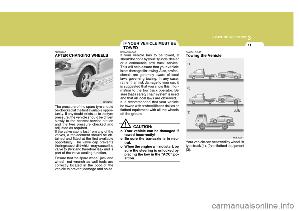
D080B01O-GAT Towing the Vehicle
HGK4030
Your vehicle can be towed by wheel lift type truck (1), (2) or flatbed equipment (3). 1)
2)
3)
dolly
Page 321 of 389
5
VEHICLE MAINTENANCE REQUIREMENTS
5
NO. 1 23 4 5678 9
10 11121314 15 1617181920 21 DESCRIPTION
GENERAL MAINTENANCE COOLING SYSTEMCOOLANTCOOLANT SPECIFIC GRAVITYMANUAL TRANSAXLE OILAUTOMATIC TRANSAXLE FLUID BRAKE PIPES, HOSES, AND CONNECTIONS BRAKE FLUIDCLUTCH FLUIDREAR BRAKE LININGS AND CYLINDERSBRAKE PADS SUSPENSION AND STEERING SYSTEM FRONT SUSPENSION BALL JOINTSPOLLEN FILTER (For Blower unit)REAR WHEEL BEARINGSTYRE CONDITION AND PRESSURE (incl. Spare)LUBRICATE LOCKS AND HINGES CHECK ALL ELECTRICAL SYSTEMS ROAD TESTCHECK ALL SYSTEMS WITH HI-SCANCHECK 4 GASDRIVE SHAFT & BOOT
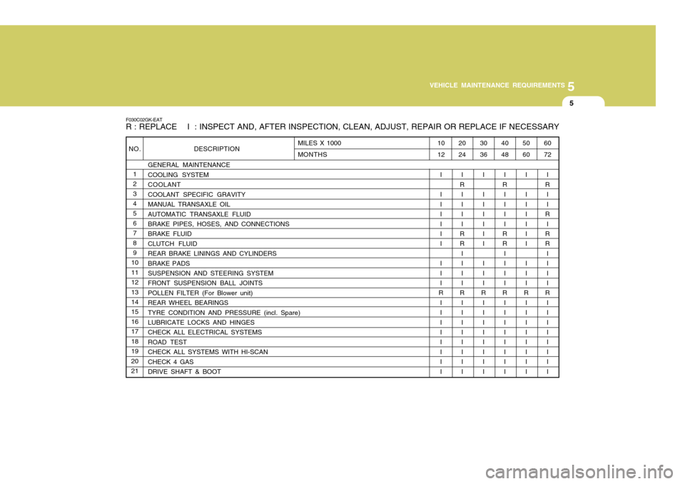
F030C02GK-EAT R : REPLACE I : INSPECT AND, AFTER INSPECTION, CLEAN, ADJUST, REPAIR OR REPLACE IF NECESSARY
60 72
I
R I I
R
I
RR
III I
R
I III I III
50 60
I I III I I I I I
R I III I III
40 48
I
R
I III
RR
III I
R I III I III
30 36
I I III I I I I I
R I III I III
20 24
I
R I III
RR
III I
R I III I III
10 12
I I III I I I I I
R I III I III
MILES X 1000 MONTHS
Page 331 of 389
6
OWNER MAINTENANCE
5ENGINE OIL
SG030A1-E The correct engine oil level is of para-
mount importance. An excessively high or low oil level may result inirreparable damage being sustained by the engine. The engine oil level must be checked on a daily basis orwhenever the vehicle is refuelled, whichever occurs sooner.
In addition, it is imperative that only
an approved grade and specificationof oil is used to avoid the possibility of serious engine damage and prema-ture wear. The use of "budget price" oil is a false economy that must be avoided if the maximum reliability anduseful life is to be obtained from the vehicle.
SG020B1-E The following items should be checked on a daily basis or whenever the vehicle is refuelled, whichever occurssooner.
o Engine oil level.
o Engine coolant level.
o Power steering fluid level.
o Brake fluid level.
o Windscreen washer fluid level.
o Battery condition.
o Tyre condition and pressures.
o Operation and cleanliness of all lighting equip-ment.
o Windscreen wiper and washer op-
eration.
o Horn operation.
o Warning lamp operation.
o Adjustment and cleanliness of mir- rors.
o Seat and seat belt adjustment and operation.
o Fluid leakage.
The vehicle must not be driven if the daily operating checks indicate that any item of equipment related to the safety or roadworthiness of the ve-hicle is not functioning correctly. DAILY OPERATING CHECKS
G030B02O-EAT Recommended Oil
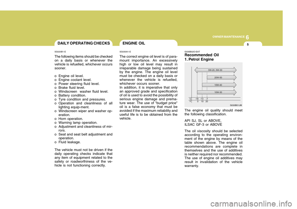
1. Petrol Engine The engine oil quality should meet the following classification. API SJ, SL or ABOVE, ILSAC GF-3 or ABOVE The oil viscosity should be selected according to the operating environ- ment of the engine by means of thetable shown above. The engine oil recommendations are complete in themselves and the use of additivesis neither required nor recommended. The use of engine oil additives may result in invalidation of the vehiclewarranty.
G030B01JM
Page 358 of 389
6OWNER MAINTENANCE
32
G290B01GK-EAT
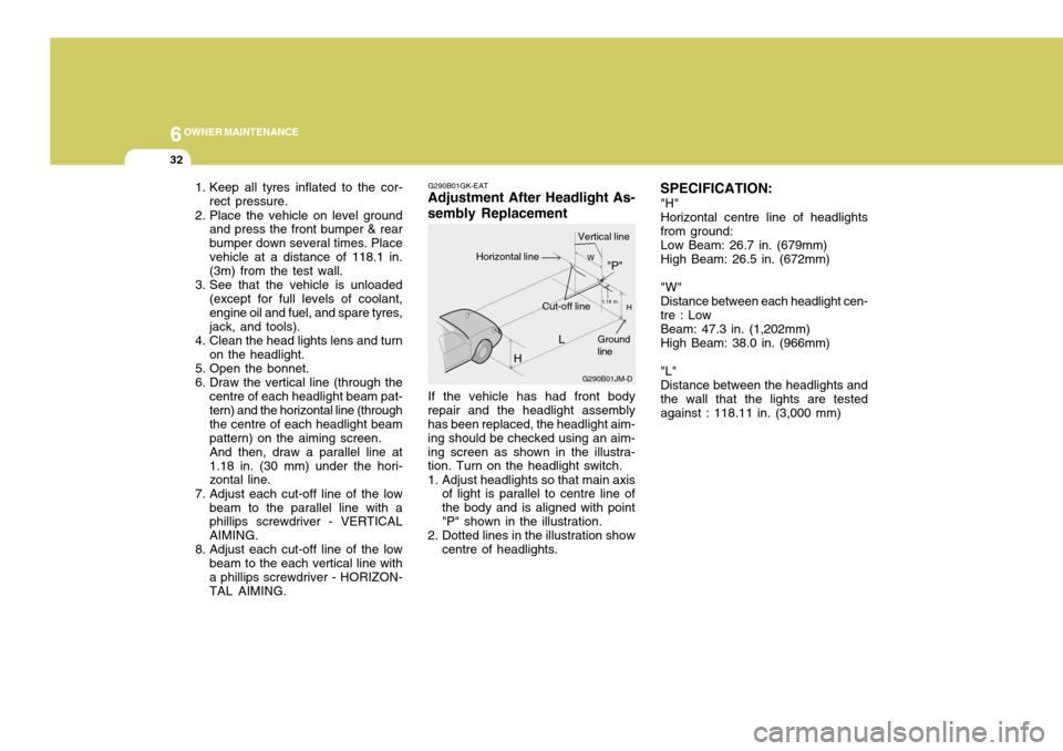
Adjustment After Headlight As- sembly Replacement
If the vehicle has had front body
repair and the headlight assembly has been replaced, the headlight aim- ing should be checked using an aim-ing screen as shown in the illustra- tion. Turn on the headlight switch.
1. Adjust headlights so that main axis of light is parallel to centre line of the body and is aligned with point"P" shown in the illustration.
2. Dotted lines in the illustration show centre of headlights. SPECIFICATION:
"H" Horizontal centre line of headlights from ground: Low Beam: 26.7 in. (679mm) High Beam: 26.5 in. (672mm) "W" Distance between each headlight cen- tre : Low Beam: 47.3 in. (1,202mm) High Beam: 38.0 in. (966mm) "L" Distance between the headlights and the wall that the lights are tested against : 118.11 in. (3,000 mm)
1. Keep all tyres inflated to the cor-
rect pressure.
2. Place the vehicle on level ground and press the front bumper & rearbumper down several times. Placevehicle at a distance of 118.1 in. (3m) from the test wall.
3. See that the vehicle is unloaded (except for full levels of coolant, engine oil and fuel, and spare tyres,jack, and tools).
4. Clean the head lights lens and turn on the headlight.
5. Open the bonnet.
6. Draw the vertical line (through the centre of each headlight beam pat- tern) and the horizontal line (through the centre of each headlight beampattern) on the aiming screen.And then, draw a parallel line at1.18 in. (30 mm) under the hori- zontal line.
7. Adjust each cut-off line of the low beam to the parallel line with aphillips screwdriver - VERTICAL AIMING.
8. Adjust each cut-off line of the low beam to the each vertical line witha phillips screwdriver - HORIZON- TAL AIMING. L
G290B01JM-D
W
H
H Cut-off line"P"
Vertical lineHorizontal line
Ground line
1.18 in.