2004 Hyundai Coupe fuel tank
[x] Cancel search: fuel tankPage 182 of 389
1CONTROLS AND EQUIPMENT
2FUEL RECOMMENDATIONS
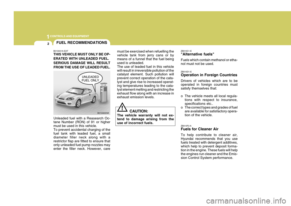
B010A01A-EAT THIS VEHICLE MUST ONLY BE OP- ERATED WITH UNLEADED FUEL.SERIOUS DAMAGE WILL RESULTFROM THE USE OF LEADED FUEL. Unleaded fuel with a Reasearch Oc- tane Number (RON) of 91 or higher must be used in this vehicle.To prevent accidental charging of the fuel tank with leaded fuel, a small diameter filler neck along with arestrictor flap are fitted to ensure that only unleaded fuel pump nozzles may enter the filler neck. However, care must be exercised when refuelling thevehicle tank from jerry cans or bymeans of a funnel that the fuel being used is unleaded. The use of leaded fuel in this vehiclewill result in irreversible pollution of the catalyst element. Such pollution will prevent correct operation of the cata-lyst and give rise to increased operat- ing temperatures leading to the cata- lyst element melting and restricting theexhaust flow along with an increase in exhaust emission levels.
!
B010A02GK
UNLEADED
FUEL ONLY
CAUTION:
The vehicle warranty will not ex- tend to damage arising from theuse of incorrect fuels. ZB010C1-E "Alternative fuels" Fuels which contain methanol or etha- nol must not be used. ZB010F2-A Fuels for Cleaner Air To help contribute to cleaner air, Hyundai recommends that you use fuels treated with detergent additives, which help to prevent deposit forma-tion in the engine. These fuels will help the engines run cleaner and the Emis- sion Control System performance.
ZB010D1-E Operation in Foreign Countries Drivers of vehicles which are to be operated in foreign countries must satisfy themselves that:
o The vehicle meets all local regula-
tions with respect to insurance, specifications etc..
o The correct types and grades of fuel
are available for satisfactory opera-tion of the vehicle.
Page 224 of 389
1CONTROLS AND EQUIPMENT
44
!
INSTRUMENT CLUSTER
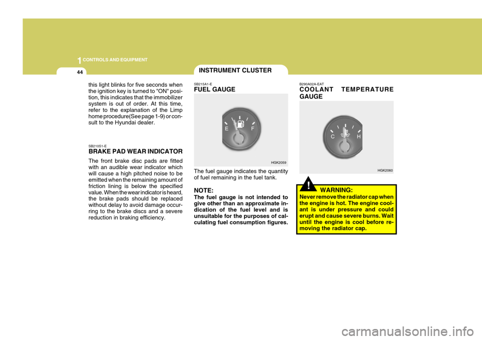
SB210S1-E BRAKE PAD WEAR INDICATOR The front brake disc pads are fitted with an audible wear indicator whichwill cause a high pitched noise to be emitted when the remaining amount of friction lining is below the specifiedvalue. When the wear indicator is heard, the brake pads should be replaced without delay to avoid damage occur-ring to the brake discs and a severe reduction in braking efficiency. SB215A1-E FUEL GAUGE The fuel gauge indicates the quantity of fuel remaining in the fuel tank. NOTE: The fuel gauge is not intended to give other than an approximate in- dication of the fuel level and isunsuitable for the purposes of cal- culating fuel consumption figures. B290A02A-EAT COOLANT TEMPERATURE GAUGE
WARNING:
Never remove the radiator cap when the engine is hot. The engine cool- ant is under pressure and could erupt and cause severe burns. Waituntil the engine is cool before re- moving the radiator cap.
HGK2059
HGK2060
this light blinks for five seconds when the ignition key is turned to "ON" posi-tion, this indicates that the immobilizer system is out of order. At this time, refer to the explanation of the Limphome procedure(See page 1-9) or con- sult to the Hyundai dealer.
Page 227 of 389
1
CONTROLS AND EQUIPMENT
47TRIP COMPUTER
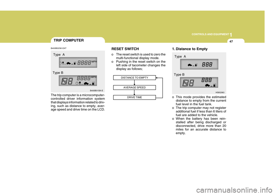
B400B02GK-EAT The trip computer is a microcomputer- controlled driver information system that displays information related to driv-ing, such as distance to empty, aver- age speed and drive time on the LCD. RESET SWITCH
o The reset switch is used to zero the
multi-functional display mode.
o Pushing in the reset switch on the left side of tacometer changes the display as follows; 1. Distance to Empty
o This mode provides the estimated
distance to empty from the current fuel level in the fuel tank.
o The trip computer may not register additional fuel if less than 6 liters offuel are added to the vehicle.
o When the battery has been rein- stalled after being discharged ordisconnected, drive more than 20miles for an accurate distance to empty.
DISTANCE TO EMPTY
AVERAGE SPEED DRIVE TIME
B400B01GK-E HGK2063
Type A
Type B Type A
Type B
Page 323 of 389
5
VEHICLE MAINTENANCE REQUIREMENTS
7EXPLANATION OF SCHEDULED MAINTENANCE ITEMS
6ZF060M1-A
o Engine oil and filter
The engine oil and filter should be changed at the intervals specified in the maintenance schedule. If the car is being driven in severe conditions,more frequent oil and filter changes are required. 6ZF060B2-A
o Drive belts
Inspect all drive belts for evidence of cuts, cracks, excessive wear or oilsaturation and replace if necessary. Drive belts should be checked periodi- cally for proper tension and adjustedas necessary. 6ZF060C1-A
o Fuel filter
A clogged filter can limit the speed at
which the vehicle may be driven, dam- age the emission system and cause hard starting. If an excessive amountof foreign matter accumulates in the fuel tank, the filter may require re- placement more frequently. After installing a new filter, run the
engine for several minutes, and checkfor leaks at the connections.
6ZF060D1-A
o Fuel lines, fuel hoses and
connections
Check the fuel lines, fuel hoses and
connections for leakage and damage. Replace any damaged or leaking parts immediately. 6ZF060E1-A o Timing belt Inspect all parts related to the timing belt for damage and deformation. Replace any damaged parts immedi- ately. 6ZF060G1-A
o Vapour hose and fuel filler cap The vapor hose and fuel filler cap should be inspected at those intervals specified in the maintenance sched- ule. Make sure that a new vapour hoseor fuel filler cap is correctly replaced.
Page 372 of 389
7EMISSION CONTROL SYSTEMS
2
SH010A1-E (Not all models) Depending upon the market for which the vehicle is destined, the emission control system will comprise one or more of the following emission controldevices.
(1) Crankcase emission control sys-
tem
(2) Evaporative emission control sys- tem
(3) Exhaust emission control systemIn order that the proper functioning of the emission control systems may be ensured, it is recommended that the vehicle is inspected and maintainedby an authorized Hyundai dealer in accordance with the maintenance schedule in this manual. EMISSION CONTROL SYS- TEMS
SH010B1-E
1. CRANKCASE EMISSION CON- TROL SYSTEM The positive crankcase ventilation system is employed to prevent air pollution caused by blow-by gases being emitted from the crankcase byintroducing fresh air to the crankcase through the air cleaner where this mixes with blow-by gases and thenpasses through the PCV valve into the intake manifold from where it sub- sequently enters the combustionchamber and is burned.
SH010C1-E
2. EVAPORATIVE EMISSION
CONTROL SYSTEM
The Evaporative Emission Control
System is designed to prevent fuelvapours from escaping into the atmo-sphere through the fuel tank ventila- tion system. SH010D1-E
3. EXHAUST EMISSION
CONTROL SYSTEM
The exhaust emission control system
is a highly effective system which controls exhaust emission while main- taining good vehicle performance. Whilst the engine is not running, fuel vapours generated inside the fuel tankare absorbed and stored in a char- coal canister. When the engine is started, the vapours stored in thecanister are drawn into the induction system through the purge control so- lenoid valve and are subsequentlyburned.The purge control solenoid valve iscontrolled by the ECU; when the en-gine coolant temperature is low or the engine is idling, the purge control valve is closed and fuel vapours re-main stored in the canister. Under normal running conditions when the engine is warm, the valve opens andthe vapours are drawn into the inlet tract and subsequently burned in the combustion chamber.
Page 373 of 389
7
EMISSION CONTROL SYSTEMS
3CATALYTIC CONVERTOR
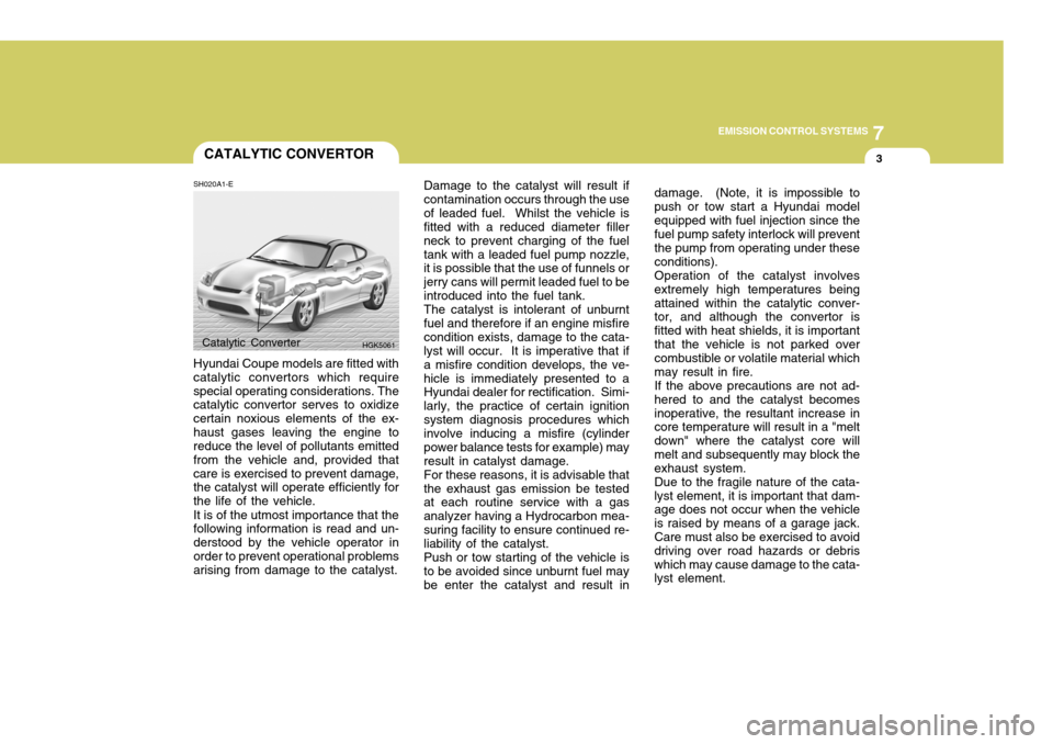
SH020A1-E Hyundai Coupe models are fitted with catalytic convertors which requirespecial operating considerations. The catalytic convertor serves to oxidize certain noxious elements of the ex-haust gases leaving the engine to reduce the level of pollutants emitted from the vehicle and, provided thatcare is exercised to prevent damage, the catalyst will operate efficiently for the life of the vehicle. It is of the utmost importance that the following information is read and un- derstood by the vehicle operator inorder to prevent operational problems arising from damage to the catalyst. Damage to the catalyst will result if contamination occurs through the useof leaded fuel. Whilst the vehicle is fitted with a reduced diameter filler neck to prevent charging of the fueltank with a leaded fuel pump nozzle, it is possible that the use of funnels or jerry cans will permit leaded fuel to beintroduced into the fuel tank.The catalyst is intolerant of unburntfuel and therefore if an engine misfirecondition exists, damage to the cata- lyst will occur. It is imperative that if a misfire condition develops, the ve-hicle is immediately presented to a Hyundai dealer for rectification. Simi- larly, the practice of certain ignitionsystem diagnosis procedures which involve inducing a misfire (cylinder power balance tests for example) mayresult in catalyst damage.For these reasons, it is advisable thatthe exhaust gas emission be tested at each routine service with a gas analyzer having a Hydrocarbon mea-suring facility to ensure continued re- liability of the catalyst. Push or tow starting of the vehicle is to be avoided since unburnt fuel may be enter the catalyst and result in
Catalytic Converter
HGK5061 damage. (Note, it is impossible to push or tow start a Hyundai modelequipped with fuel injection since the fuel pump safety interlock will prevent the pump from operating under theseconditions).Operation of the catalyst involvesextremely high temperatures beingattained within the catalytic conver- tor, and although the convertor is fitted with heat shields, it is importantthat the vehicle is not parked over combustible or volatile material which may result in fire.If the above precautions are not ad-hered to and the catalyst becomesinoperative, the resultant increase in core temperature will result in a "melt down" where the catalyst core willmelt and subsequently may block the exhaust system. Due to the fragile nature of the cata- lyst element, it is important that dam- age does not occur when the vehicleis raised by means of a garage jack. Care must also be exercised to avoid driving over road hazards or debriswhich may cause damage to the cata- lyst element.
Page 382 of 389

9 VEHICLE SPECIFICATIONS
2
J010A01GK-EAT MEASUREMENT 173(4395)
69.3(1760) 52.4(1330) 99.6(2530)58.7(1490) 58.7(1490)
Overall length Overall width Overall height (unladen)Wheel base Wheel tread FrontRear
Type Wheel free play Rack strokeOil pump type Rack and pinion0 ~ 1.18 in. (0 ~ 30 mm) 5.20 in. (132 mm) Vane type
Option
Item Battery Alternator
in. (mm)
Fuel tank
capacity Imp.gal
12 2.7L
MF 68AH
120A
195/65 R15, 205/55 R16, 215/45 R17
2.0L
MF 68AH 90A
Dual hydraulic with brake booster Ventilated disc Solid discCable
Type Front brake type Rear brake typeParking brake
US.gal
14.5Liter55
Standard T125/70 R16 (Temporary)
1.6L
MF 60AH
90A
SJ030A1-E FUEL SYSTEM
J020A01GK-EATPOWER STEERING J030A01GK-EAT TYRE J040A03GK-GAT ELECTRICAL
J050A01GK-GAT BRAKE
J035A01GK-DATSPARE TYRE