2004 DODGE TOWN AND COUNTRY steering
[x] Cancel search: steeringPage 685 of 2585
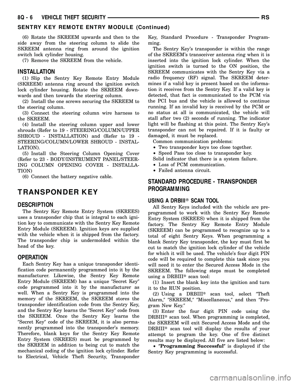
(6) Rotate the SKREEM upwards and then to the
side away from the steering column to slide the
SKREEM antenna ring from around the ignition
switch lock cylinder housing.
(7) Remove the SKREEM from the vehicle.
INSTALLATION
(1) Slip the Sentry Key Remote Entry Module
(SKREEM) antenna ring around the ignition switch
lock cylinder housing. Rotate the SKREEM down-
wards and then towards the steering column.
(2) Install the one screws securing the SKREEM to
the steering column.
(3) Connect the steering column wire harness to
the SKREEM.
(4) Install the steering column upper and lower
shrouds (Refer to 19 - STEERING/COLUMN/UPPER
SHROUD - INSTALLATION) and (Refer to 19 -
STEERING/COLUMN/LOWER SHROUD - INSTAL-
LATION).
(5) Install the Steering Column Opening Cover
(Refer to 23 - BODY/INSTRUMENT PANEL/STEER-
ING COLUMN OPENING COVER - INSTALLA-
TION)
(6) Connect the battery negative cable.
TRANSPONDER KEY
DESCRIPTION
The Sentry Key Remote Entry System (SKREES)
uses a transponder chip that is integral to each igni-
tion key to communicate with the Sentry Key Remote
Entry Module (SKREEM). Ignition keys are supplied
with the vehicle when it is shipped from the factory.
The transponder chip is undermolded within the
head of the key.
OPERATION
Each Sentry Key has a unique transponder identi-
fication code permanently programmed into it by the
manufacturer. Likewise, the Sentry Key Remote
Entry Module (SKREEM) has a unique9Secret Key9
code programmed into it by the manufacturer as
well. When a Sentry Key is programmed into the
memory of the SKREEM, the SKREEM stores the
transponder identification code from the Sentry Key,
and the Sentry Key learns the9Secret Key9code from
the SKREEM. Once the Sentry Key learns the
9Secret Key9code of the SKREEM, it is also perma-
nently programmed into the transponder's memory.
Therefore, blank keys for the Sentry Key Remote
Entry System (SKREES) must be programmed by
the SKREEM in addition to being cut to match the
mechanical coding of the ignition lock cylinder. Refer
to Electrical, Vehicle Theft Security, TransponderKey, Standard Procedure - Transponder Program-
ming.
The Sentry Key's transponder is within the range
of the SKREEM's transceiver antenna ring when it is
inserted into the ignition lock cylinder. When the
ignition switch is turned to the ON position, the
SKREEM communicates with the Sentry Key via a
radio frequency (RF) signal. The SKREEM deter-
mines if a valid key is present based on the informa-
tion it receives from the Sentry Key. If a valid key is
detected, that fact is communicated to the PCM via
the PCI bus and the vehicle is allowed to continue
running. If an invalid key is received by the PCM or
no status at all is communicated, the vehicle will
stall after two (2) seconds of running. The indicator
light will be flashing at this point. The Sentry Key's
transponder can not be repaired. If it is faulty or
damaged, it must be replaced.
Common communication problems:
²Two transponder keys too close together.
²Speed Pass too close to transponder key.
Solid indicator that there is a system failure.
²Loss of PCM communication.
²Failed antenna circuit.
STANDARD PROCEDURE - TRANSPONDER
PROGRAMMING
USING A DRBIIITSCAN TOOL
All Sentry Keys included with the vehicle are pre-
programmed to work with the Sentry Key Remote
Entry System (SKREES) when it is shipped from the
factory. The Sentry Key Remote Entry Module
(SKREEM) can be programmed to recognize up to a
total of eight Sentry Keys. When programming a
blank Sentry Key transponder, the key must first be
cut to match the ignition lock cylinder of the vehicle
for which it will be used. The vehicle's four digit PIN
code will be required to complete this task since you
will need it to enter the Secured Access Mode in the
SKREEM. The following steps must be completed
using a DRBIIItscan tool:
(1) Insert the blank key into the ignition and turn
it to the RUN position.
(2) Using a DRBIIItscan tool, select9Theft
Alarm,99SKREEM,99Miscellaneous,9and then9Pro-
gram New Key.9
(3) Enter the four digit PIN code using the
DRBIIItscan tool. When programming is completed,
the SKREEM will exit Secured Access Mode and the
DRBIIItscan tool will display the results of your
attempt to program the key. One of five distinct
results may be displayed. All five are listed below:
²(Programming Successful(is displayed if the
Sentry Key programming is successful.
8Q - 6 VEHICLE THEFT SECURITYRS
SENTRY KEY REMOTE ENTRY MODULE (Continued)
Page 711 of 2585
DESCRIPTION - CIRCUIT FUNCTIONS
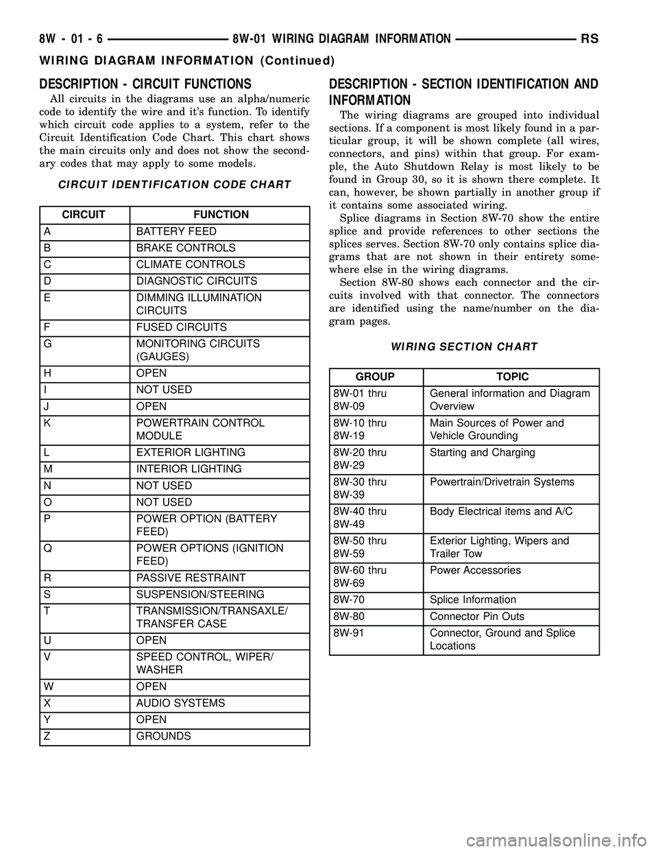
All circuits in the diagrams use an alpha/numeric
code to identify the wire and it's function. To identify
which circuit code applies to a system, refer to the
Circuit Identification Code Chart. This chart shows
the main circuits only and does not show the second-
ary codes that may apply to some models.
CIRCUIT IDENTIFICATION CODE CHART
CIRCUIT FUNCTION
A BATTERY FEED
B BRAKE CONTROLS
C CLIMATE CONTROLS
D DIAGNOSTIC CIRCUITS
E DIMMING ILLUMINATION
CIRCUITS
F FUSED CIRCUITS
G MONITORING CIRCUITS
(GAUGES)
H OPEN
I NOT USED
J OPEN
K POWERTRAIN CONTROL
MODULE
L EXTERIOR LIGHTING
M INTERIOR LIGHTING
N NOT USED
O NOT USED
P POWER OPTION (BATTERY
FEED)
Q POWER OPTIONS (IGNITION
FEED)
R PASSIVE RESTRAINT
S SUSPENSION/STEERING
T TRANSMISSION/TRANSAXLE/
TRANSFER CASE
U OPEN
V SPEED CONTROL, WIPER/
WASHER
W OPEN
X AUDIO SYSTEMS
Y OPEN
Z GROUNDS
DESCRIPTION - SECTION IDENTIFICATION AND
INFORMATION
The wiring diagrams are grouped into individual
sections. If a component is most likely found in a par-
ticular group, it will be shown complete (all wires,
connectors, and pins) within that group. For exam-
ple, the Auto Shutdown Relay is most likely to be
found in Group 30, so it is shown there complete. It
can, however, be shown partially in another group if
it contains some associated wiring.
Splice diagrams in Section 8W-70 show the entire
splice and provide references to other sections the
splices serves. Section 8W-70 only contains splice dia-
grams that are not shown in their entirety some-
where else in the wiring diagrams.
Section 8W-80 shows each connector and the cir-
cuits involved with that connector. The connectors
are identified using the name/number on the dia-
gram pages.
WIRING SECTION CHART
GROUP TOPIC
8W-01 thru
8W-09General information and Diagram
Overview
8W-10 thru
8W-19Main Sources of Power and
Vehicle Grounding
8W-20 thru
8W-29Starting and Charging
8W-30 thru
8W-39Powertrain/Drivetrain Systems
8W-40 thru
8W-49Body Electrical items and A/C
8W-50 thru
8W-59Exterior Lighting, Wipers and
Trailer Tow
8W-60 thru
8W-69Power Accessories
8W-70 Splice Information
8W-80 Connector Pin Outs
8W-91 Connector, Ground and Splice
Locations
8W - 01 - 6 8W-01 WIRING DIAGRAM INFORMATIONRS
WIRING DIAGRAM INFORMATION (Continued)
Page 1233 of 2585
CONNECTOR NAME/NUMBER COLOR LOCATION FIG.
Blower Motor Resistor C1 (MTC) BK Right Side of HVAC N/S
Blower Motor Resistor C2 (MTC) BK Right Side of HVAC N/S
Body Control Module C1 BK Under Left Instrument Panel 41, 42
Body Control Module C2 BK/GN Under Left Instrument Panel 41, 42
Body Control Module C3 BK/WT Under Left Instrument Panel 41, 42
Body Control Module C4 BK/GY Under Left Instrument Panel 20, 21, 30
Body Control Module C5 BK Under Left Instrument Panel 20, 21, 30
Boost Pressure Sensor (Diesel) BK Top Left of Engine 15
Brake Fuid Level Switch BK On Master Cylinder 6
Brake Lamp Switch BK At Top Of Brake Pedal 41, 42
Brake Transmission Shift
Interlock Solenoid (EATX)BK Near Steering Column 20, 21, 22, 31
C100 BK Left Fender Shield 5, 11
C101 LTGY Left Fender Shield 5
C102 (Gas) BK At Fuel Rail 11, 17
C103 (Diesel) BK Left Side Engine Compartment N/S
C104 (Except Export LTGY Near Controller Antilock Brake 18
C106 (Export) BK/YL Near Left Headlamp Leveling Motor N/S
C107 (Export) BK/YL Near Right Headlamp Leveling
MotorN/S
C110 (Gas Export) BK Left Front Engine 11
C111 (EATX) LTGY Left Front Engine 11
C112 (Except Export) BK Near T/O for C101 N/S
C200 GY Left Side Instrument Panel 20, 21, 30, 41, 42
C201 YL Left Side Instrument Panel 20, 21, 30, 41, 42
C202 GY Right Side Instrument Panel A/C
Heater Unit20, 24, 29
C204 (Premium NAT/WT Rear of Radio 50
C300 (LHD) BK Left Front Door Lower 36, 43
C300 (RHD) BK Right Front Door Lower N/S
C301 LTGY Left Front Door Upper 36, 43
C302 LTGY Right Front Door Upper 8, 39, 44
C303 (LHD) BK Right Front Door Lower 8, 44
C303 (RHD) BK Left Front Door Lower 39, 44
C304 Left Wire Track Seat to Body 32
C305 GY Wire Track Seat to Body 32 33
C306 (RHD) YL Right Wire Track Seat to Body 33
C307 (Heated Seats) GY Right Wire Track Seat to Body N/S
C308 GN Left Rear Sliding Door 40
C309 GN/GY Right Rear Sliding Door 32, 33, 39
C310 (Front Console) BK At Front Console 34
C311 (3 Zone HVAC) GY Rear A/C Switch 40
C312 GY Right B Pillar 33, 39, 50
8W - 91 - 2 8W-91 CONNECTOR/GROUND/SPLICE LOCATIONRS
CONNECTOR/GROUND/SPLICE LOCATION (Continued)
Page 1234 of 2585
CONNECTOR NAME/NUMBER COLOR LOCATION FIG.
C313 (Rear Console) BK At Rear Console 34
C314 BK Left Side Liftgate 49
C315 (Power Liftgate) BK Right Side Liftgate 49
C316 (Power Sliding Door) BK Wire Track to Sliding Door N/S
C317 (Power Sliding Door) BK Right Sliding Door 32, 45
C318 (Trailer Tow) BK Left Quarter N/S
C320 DKGY Driver Power Seat on Seat Harness N/S
C321 DKGY Under Passenger Seat N/S
C322 (Memory) BK On Seat Harness to Body 32
C324 (Manual Sliding Door) BK Left Sliding Door N/S
C325 (Manual Sliding Door) BK Right Sliding Door 32
C326 YL At Driver Side Airbag N/S
C327 YL At Passenger Side Airbag N/S
C328 (Sunroof) Left Quarter Panel 47
C329 (Diesel) BK Near Fuel Tank N/S
C330 (Diesel) LTGY Near Throttle Body 15, 16
C331 (Diesel) BK/GY Left Rear Engine Compartment N/S
C332 (3 Zone ATC) BK/LTGN Near T/O for Right Rear Lamp
AssemblyN/S
C333 (Except Export DKGY Left Side Instrument Panel 21
Cabin Heater Assist C1 (Diesel) BK Top of Engine N/S
Cabin Heater Assist C2 (Diesel) BK Top of Engine N/S
Camshaft Position Sensor (Gas) BK Rear of Cylinder Head
Right Side of Engine11 , 1 7
Camshaft Position Sensor
(Diesel)BK Rear of Cylinder Head 15, 16
CD Changer Behind CD Changer N/S
Center High Mounted Stop Lamp BK At Lamp 49
Clockspring - C1 WT Steering Column 20, 21, 22, 23, 31
Clockspring - C2 YL Steering Column 20, 21, 22, 23, 31
Clockspring - C3 BK Steering Column N/S
Clockspring - C4 BK Steering Column N/S
Clutch Pedal Interlock Switch BK At Switch/Driver Side 42
Clutch Pedal Upstop Switch
(Diesel)RD At Switch/Driver Side 42
Controller Anti-Lock Brake BK Right Side of Engine Compartment 11, 16, 17, 18
Crank Case Ventilation Heater
(Diesel)BK Top of Cylinder Head 15
Crankshaft Position Sensor
(Diesel)BK Rear of Engine 16
Crankshaft Position Sensor (Gas) BK Rear of Engine 13, 17
Data Link Connector WT Lower Instrument Panel Near
Steering Column41, 42
Dosing Pump (Diesel) BK Top of Engine N/S
RS8W-91 CONNECTOR/GROUND/SPLICE LOCATION8W-91-3
CONNECTOR/GROUND/SPLICE LOCATION (Continued)
Page 1235 of 2585
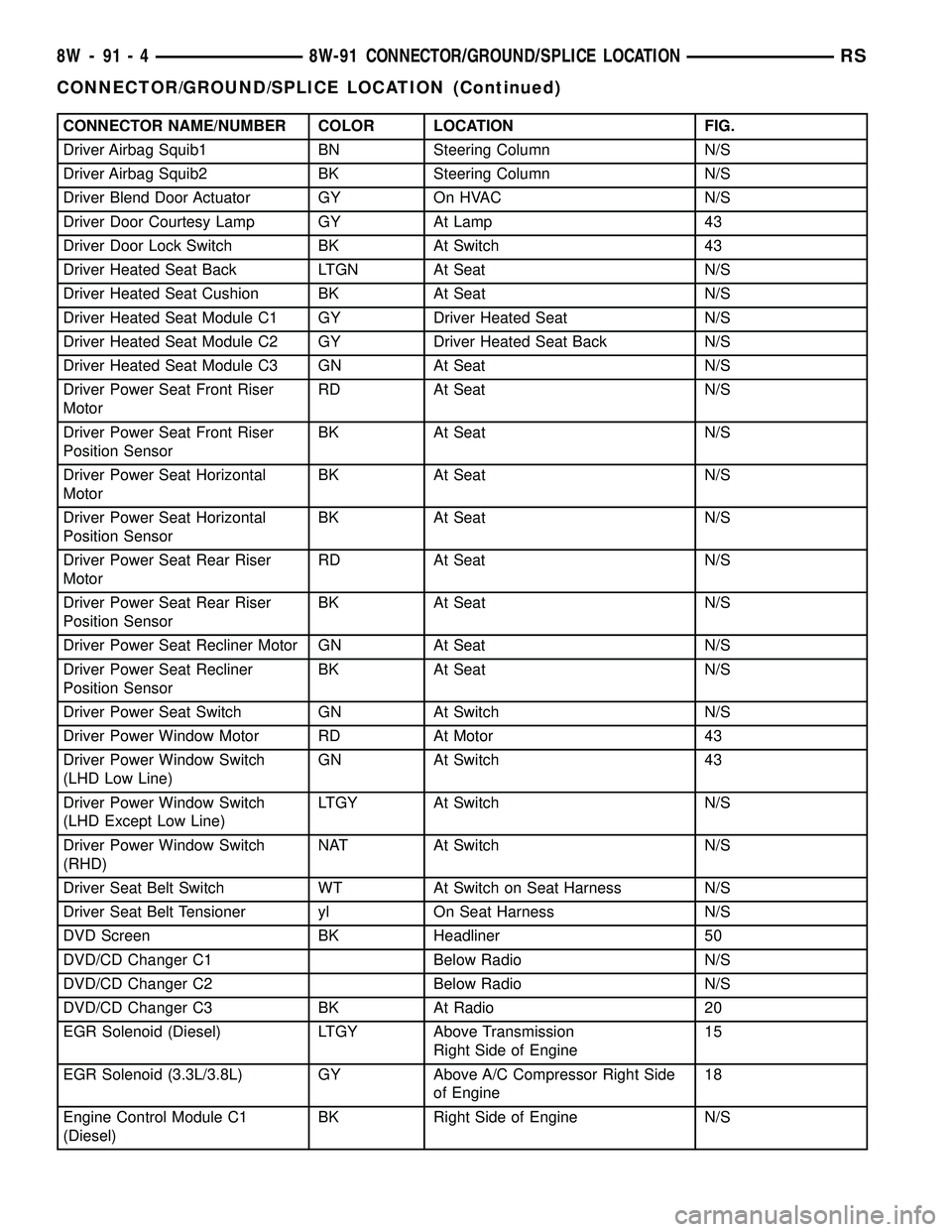
CONNECTOR NAME/NUMBER COLOR LOCATION FIG.
Driver Airbag Squib1 BN Steering Column N/S
Driver Airbag Squib2 BK Steering Column N/S
Driver Blend Door Actuator GY On HVAC N/S
Driver Door Courtesy Lamp GY At Lamp 43
Driver Door Lock Switch BK At Switch 43
Driver Heated Seat Back LTGN At Seat N/S
Driver Heated Seat Cushion BK At Seat N/S
Driver Heated Seat Module C1 GY Driver Heated Seat N/S
Driver Heated Seat Module C2 GY Driver Heated Seat Back N/S
Driver Heated Seat Module C3 GN At Seat N/S
Driver Power Seat Front Riser
MotorRD At Seat N/S
Driver Power Seat Front Riser
Position SensorBK At Seat N/S
Driver Power Seat Horizontal
MotorBK At Seat N/S
Driver Power Seat Horizontal
Position SensorBK At Seat N/S
Driver Power Seat Rear Riser
MotorRD At Seat N/S
Driver Power Seat Rear Riser
Position SensorBK At Seat N/S
Driver Power Seat Recliner Motor GN At Seat N/S
Driver Power Seat Recliner
Position SensorBK At Seat N/S
Driver Power Seat Switch GN At Switch N/S
Driver Power Window Motor RD At Motor 43
Driver Power Window Switch
(LHD Low Line)GN At Switch 43
Driver Power Window Switch
(LHD Except Low Line)LTGY At Switch N/S
Driver Power Window Switch
(RHD)NAT At Switch N/S
Driver Seat Belt Switch WT At Switch on Seat Harness N/S
Driver Seat Belt Tensioner yl On Seat Harness N/S
DVD Screen BK Headliner 50
DVD/CD Changer C1 Below Radio N/S
DVD/CD Changer C2 Below Radio N/S
DVD/CD Changer C3 BK At Radio 20
EGR Solenoid (Diesel) LTGY Above Transmission
Right Side of Engine15
EGR Solenoid (3.3L/3.8L) GY Above A/C Compressor Right Side
of Engine18
Engine Control Module C1
(Diesel)BK Right Side of Engine N/S
8W - 91 - 4 8W-91 CONNECTOR/GROUND/SPLICE LOCATIONRS
CONNECTOR/GROUND/SPLICE LOCATION (Continued)
Page 1237 of 2585
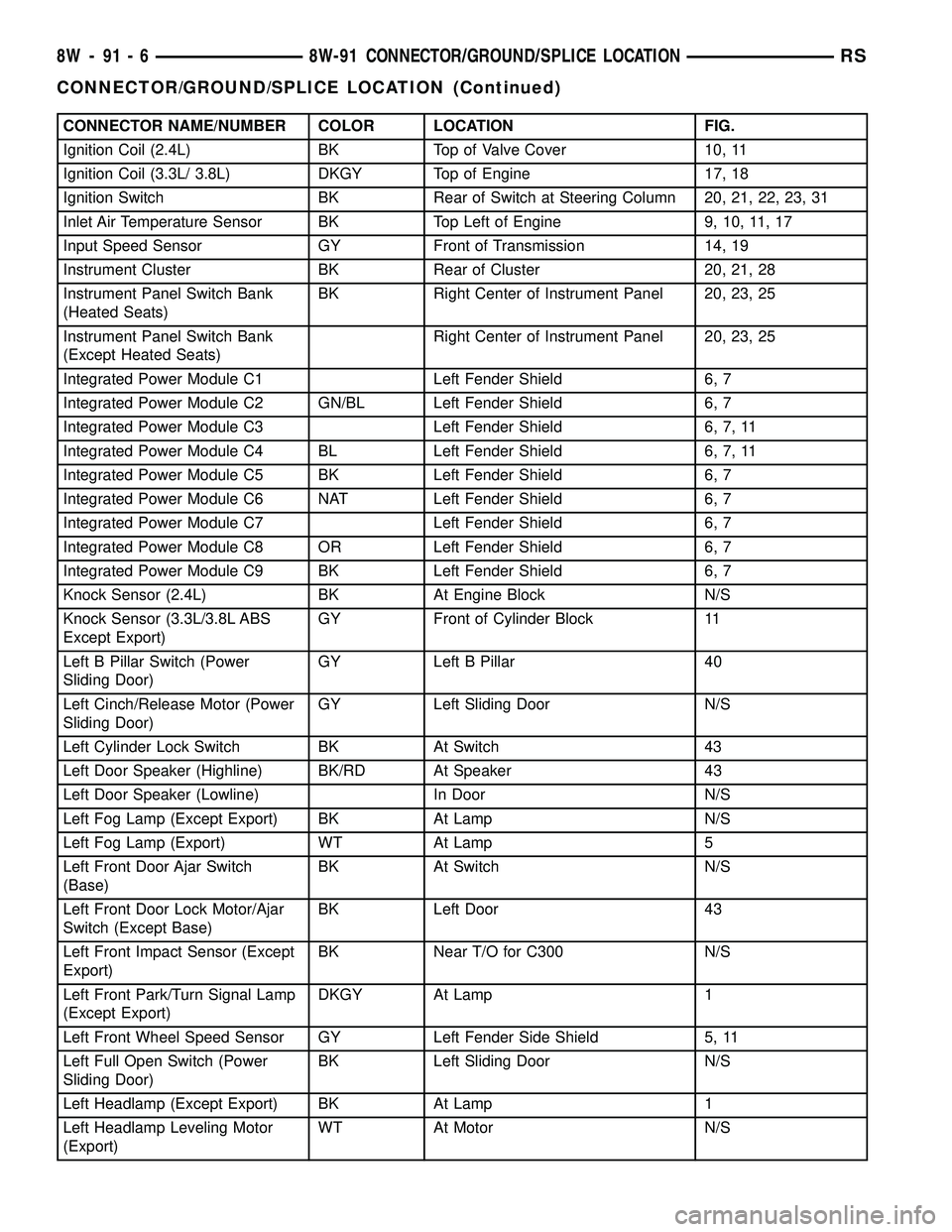
CONNECTOR NAME/NUMBER COLOR LOCATION FIG.
Ignition Coil (2.4L) BK Top of Valve Cover 10, 11
Ignition Coil (3.3L/ 3.8L) DKGY Top of Engine 17, 18
Ignition Switch BK Rear of Switch at Steering Column 20, 21, 22, 23, 31
Inlet Air Temperature Sensor BK Top Left of Engine 9, 10, 11, 17
Input Speed Sensor GY Front of Transmission 14, 19
Instrument Cluster BK Rear of Cluster 20, 21, 28
Instrument Panel Switch Bank
(Heated Seats)BK Right Center of Instrument Panel 20, 23, 25
Instrument Panel Switch Bank
(Except Heated Seats)Right Center of Instrument Panel 20, 23, 25
Integrated Power Module C1 Left Fender Shield 6, 7
Integrated Power Module C2 GN/BL Left Fender Shield 6, 7
Integrated Power Module C3 Left Fender Shield 6, 7, 11
Integrated Power Module C4 BL Left Fender Shield 6, 7, 11
Integrated Power Module C5 BK Left Fender Shield 6, 7
Integrated Power Module C6 NAT Left Fender Shield 6, 7
Integrated Power Module C7 Left Fender Shield 6, 7
Integrated Power Module C8 OR Left Fender Shield 6, 7
Integrated Power Module C9 BK Left Fender Shield 6, 7
Knock Sensor (2.4L) BK At Engine Block N/S
Knock Sensor (3.3L/3.8L ABS
Except Export)GY Front of Cylinder Block 11
Left B Pillar Switch (Power
Sliding Door)GY Left B Pillar 40
Left Cinch/Release Motor (Power
Sliding Door)GY Left Sliding Door N/S
Left Cylinder Lock Switch BK At Switch 43
Left Door Speaker (Highline) BK/RD At Speaker 43
Left Door Speaker (Lowline) In Door N/S
Left Fog Lamp (Except Export) BK At Lamp N/S
Left Fog Lamp (Export) WT At Lamp 5
Left Front Door Ajar Switch
(Base)BK At Switch N/S
Left Front Door Lock Motor/Ajar
Switch (Except Base)BK Left Door 43
Left Front Impact Sensor (Except
Export)BK Near T/O for C300 N/S
Left Front Park/Turn Signal Lamp
(Except Export)DKGY At Lamp 1
Left Front Wheel Speed Sensor GY Left Fender Side Shield 5, 11
Left Full Open Switch (Power
Sliding Door)BK Left Sliding Door N/S
Left Headlamp (Except Export) BK At Lamp 1
Left Headlamp Leveling Motor
(Export)WT At Motor N/S
8W - 91 - 6 8W-91 CONNECTOR/GROUND/SPLICE LOCATIONRS
CONNECTOR/GROUND/SPLICE LOCATION (Continued)
Page 1238 of 2585
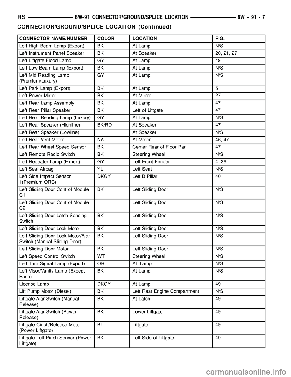
CONNECTOR NAME/NUMBER COLOR LOCATION FIG.
Left High Beam Lamp (Export) BK At Lamp N/S
Left Instrument Panel Speaker BK At Speaker 20, 21, 27
Left Liftgate Flood Lamp GY At Lamp 49
Left Low Beam Lamp (Export) BK At Lamp N/S
Left Mid Reading Lamp
(Premium/Luxury)GY At Lamp N/S
Left Park Lamp (Export) BK At Lamp 5
Left Power Mirror BK At Mirror 27
Left Rear Lamp Assembly BK At Lamp 47
Left Rear Pillar Speaker BK Left of Liftgate 47
Left Rear Reading Lamp (Luxury) GY At Lamp N/S
Left Rear Speaker (Highline) BK/RD At Speaker 47
Left Rear Speaker (Lowline) At Speaker N/S
Left Rear Vent Motor NAT At Motor 46, 47
Left Rear Wheel Speed Sensor BK Center Rear of Floor Pan 47
Left Remote Radio Switch BK Steering Wheel N/S
Left Repeater Lamp (Export) GY Left Front Fender 4, 36
Left Seat Airbag YL Left Seat N/S
Left Side Impact Sensor
1(Premium ORC)DKGY Left B Pillar 40
Left Sliding Door Control Module
C1BK Left Sliding Door N/S
Left Sliding Door Control Module
C2Left Sliding Door N/S
Left Sliding Door Latch Sensing
SwitchBK Left Sliding Door N/S
Left Sliding Door Lock Motor BK Left Sliding Door N/S
Left Sliding Door Lock Motor/Ajar
Switch (Manual Sliding Door)BK Left Sliding Door N/S
Left Sliding Door Motor BK Left Sliding Door N/S
Left Speed Control Switch WT Steering Wheel N/S
Left Turn Signal Lamp (Export) OR AT Lamp N/S
Left Visor/Vanity Lamp (Except
Base)BK At Lamp N/S
License Lamp DKGY At Lamp 49
Lift Pump Motor (Diesel) BK Left Rear Engine Compartment N/S
Liftgate Ajar Switch (Manual
Release)BK At Latch 49
Liftgate Ajar Switch (Power
Release)BK Lower Liftgate 49
Liftgate Cinch/Release Motor
(Power Liftgate)BL Liftgate 49
Liftgate Left Pinch Sensor (Power
Liftgate)BK Left Side of Liftgate 49
RS8W-91 CONNECTOR/GROUND/SPLICE LOCATION8W-91-7
CONNECTOR/GROUND/SPLICE LOCATION (Continued)
Page 1239 of 2585
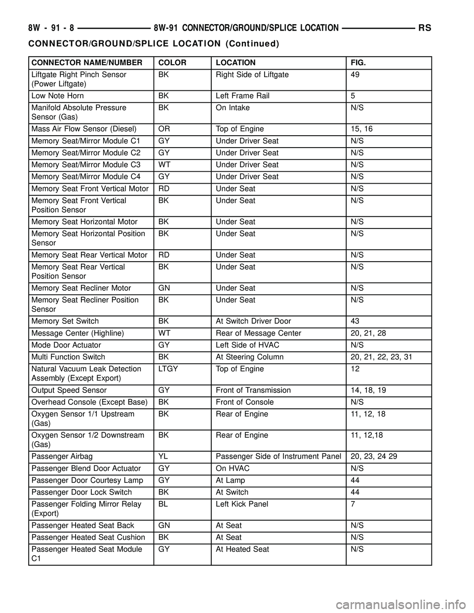
CONNECTOR NAME/NUMBER COLOR LOCATION FIG.
Liftgate Right Pinch Sensor
(Power Liftgate)BK Right Side of Liftgate 49
Low Note Horn BK Left Frame Rail 5
Manifold Absolute Pressure
Sensor (Gas)BK On Intake N/S
Mass Air Flow Sensor (Diesel) OR Top of Engine 15, 16
Memory Seat/Mirror Module C1 GY Under Driver Seat N/S
Memory Seat/Mirror Module C2 GY Under Driver Seat N/S
Memory Seat/Mirror Module C3 WT Under Driver Seat N/S
Memory Seat/Mirror Module C4 GY Under Driver Seat N/S
Memory Seat Front Vertical Motor RD Under Seat N/S
Memory Seat Front Vertical
Position SensorBK Under Seat N/S
Memory Seat Horizontal Motor BK Under Seat N/S
Memory Seat Horizontal Position
SensorBK Under Seat N/S
Memory Seat Rear Vertical Motor RD Under Seat N/S
Memory Seat Rear Vertical
Position SensorBK Under Seat N/S
Memory Seat Recliner Motor GN Under Seat N/S
Memory Seat Recliner Position
SensorBK Under Seat N/S
Memory Set Switch BK At Switch Driver Door 43
Message Center (Highline) WT Rear of Message Center 20, 21, 28
Mode Door Actuator GY Left Side of HVAC N/S
Multi Function Switch BK At Steering Column 20, 21, 22, 23, 31
Natural Vacuum Leak Detection
Assembly (Except Export)LTGY Top of Engine 12
Output Speed Sensor GY Front of Transmission 14, 18, 19
Overhead Console (Except Base) BK Front of Console N/S
Oxygen Sensor 1/1 Upstream
(Gas)BK Rear of Engine 11, 12, 18
Oxygen Sensor 1/2 Downstream
(Gas)BK Rear of Engine 11, 12,18
Passenger Airbag YL Passenger Side of Instrument Panel 20, 23, 24 29
Passenger Blend Door Actuator GY On HVAC N/S
Passenger Door Courtesy Lamp GY At Lamp 44
Passenger Door Lock Switch BK At Switch 44
Passenger Folding Mirror Relay
(Export)BL Left Kick Panel 7
Passenger Heated Seat Back GN At Seat N/S
Passenger Heated Seat Cushion BK At Seat N/S
Passenger Heated Seat Module
C1GY At Heated Seat N/S
8W - 91 - 8 8W-91 CONNECTOR/GROUND/SPLICE LOCATIONRS
CONNECTOR/GROUND/SPLICE LOCATION (Continued)