2004 DODGE TOWN AND COUNTRY roof rack
[x] Cancel search: roof rackPage 381 of 2585
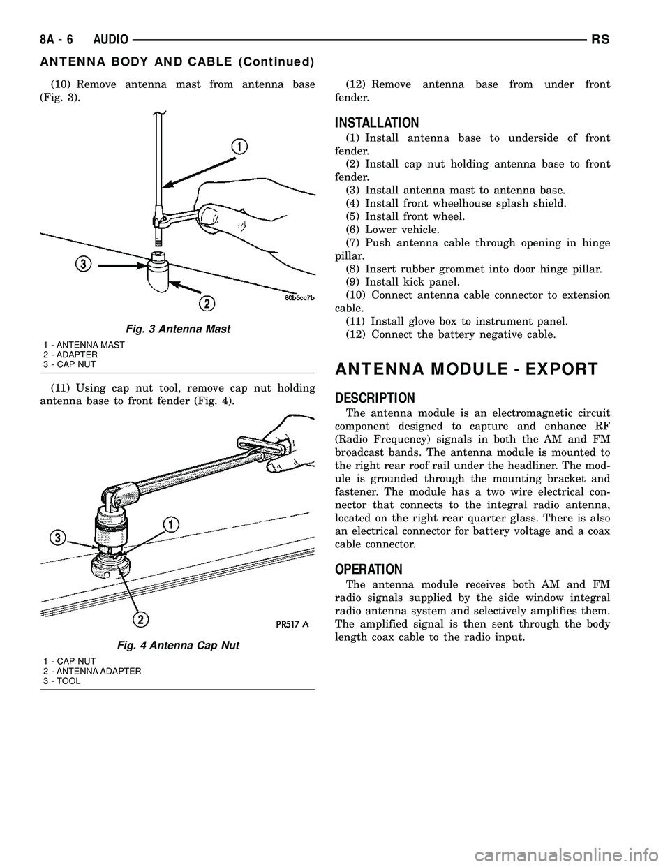
(10) Remove antenna mast from antenna base
(Fig. 3).
(11) Using cap nut tool, remove cap nut holding
antenna base to front fender (Fig. 4).(12) Remove antenna base from under front
fender.
INSTALLATION
(1) Install antenna base to underside of front
fender.
(2) Install cap nut holding antenna base to front
fender.
(3) Install antenna mast to antenna base.
(4) Install front wheelhouse splash shield.
(5) Install front wheel.
(6) Lower vehicle.
(7) Push antenna cable through opening in hinge
pillar.
(8) Insert rubber grommet into door hinge pillar.
(9) Install kick panel.
(10) Connect antenna cable connector to extension
cable.
(11) Install glove box to instrument panel.
(12) Connect the battery negative cable.
ANTENNA MODULE - EXPORT
DESCRIPTION
The antenna module is an electromagnetic circuit
component designed to capture and enhance RF
(Radio Frequency) signals in both the AM and FM
broadcast bands. The antenna module is mounted to
the right rear roof rail under the headliner. The mod-
ule is grounded through the mounting bracket and
fastener. The module has a two wire electrical con-
nector that connects to the integral radio antenna,
located on the right rear quarter glass. There is also
an electrical connector for battery voltage and a coax
cable connector.
OPERATION
The antenna module receives both AM and FM
radio signals supplied by the side window integral
radio antenna system and selectively amplifies them.
The amplified signal is then sent through the body
length coax cable to the radio input.
Fig. 3 Antenna Mast
1 - ANTENNA MAST
2 - ADAPTER
3 - CAP NUT
Fig. 4 Antenna Cap Nut
1 - CAP NUT
2 - ANTENNA ADAPTER
3 - TOOL
8A - 6 AUDIORS
ANTENNA BODY AND CABLE (Continued)
Page 560 of 2585

MESSAGE SYSTEMS
TABLE OF CONTENTS
page page
OVERHEAD CONSOLE
DESCRIPTION..........................1
OPERATION............................2
DIAGNOSIS AND TESTING - OVERHEAD
CONSOLE............................2
STANDARD PROCEDURE
STANDARD PROCEDURE - READING/
COURTESY LAMP REPLACEMENT.........3
STANDARD PROCEDURE - MODULE LAMP
REPLACEMENT.......................3
STANDARD PROCEDURE - COMPASS
CALIBRATION.........................3
STANDARD PROCEDURE - COMPASS
DEMAGNETIZING......................4
STANDARD PROCEDURE - COMPASS
VARIATION ADJUSTMENT................5
REMOVAL - OVERHEAD CONSOLE..........6
INSTALLATION..........................6
SPECIAL TOOLS
OVERHEAD CONSOLE..................6
ELECTRONIC VEHICLE INFO CENTER
DESCRIPTION..........................6
OPERATION............................7
DIAGNOSIS AND TESTING - ELECTRONIC
VEHICLE INFORMATION CENTER.........7
STANDARD PROCEDURE - ELECTRONIC
VEHICLE INFORMATION CENTER
PROGRAMMING.......................7
REMOVAL.............................9INSTALLATION..........................9
COMPASS/MINI-TRIP COMPUTER
DESCRIPTION..........................9
OPERATION............................9
DIAGNOSIS AND TESTING - COMPASS
MINI-TRIP COMPUTER.................10
REMOVAL.............................10
INSTALLATION.........................10
UNIVERSAL TRANSMITTER
DESCRIPTION.........................10
OPERATION...........................10
DIAGNOSIS AND TESTING - UNIVERSAL
TRANSMITTER.......................10
STANDARD PROCEDURE
STANDARD PROCEDURE - SETTING
TRANSMITTER CODES.................11
STANDARD PROCEDURE - ERASING
TRANSMITTER CODES.................11
REMOVAL.............................11
AMBIENT TEMP SENSOR
DESCRIPTION.........................11
OPERATION...........................11
DIAGNOSIS AND TESTING
DIAGNOSIS AND TESTING - AMBIENT
TEMPERATURE SENSOR...............12
DIAGNOSIS AND TESTING - AMBIENT
TEMPERATURE SENSOR CIRCUIT........12
REMOVAL.............................12
INSTALLATION.........................12
OVERHEAD CONSOLE
DESCRIPTION
Three overhead consoles are available on RS/RG
models. These are the Electronic Vehicle Information
Center (EVIC), Compass Mini-Trip Computer
(CMTC) or a Compass Temperature Computer (CT).
All consoles are equipped with two reading/courtesy
lamps and if the vehicle is equipped with a power
liftgate or power sliding door(s) the overhead console
will also include command switches for these fea-
tures. The overhead console is mounted with one
screw and two snap clips to a molded plastic retainer
bracket located above the headliner.
DESCRIPTION - COMPASS
All the available overhead consoles on this model
include Compass information. While in the compass/temperature mode, the compass will display the
direction in which the vehicle is pointed using the
eight major compass headings (Examples: north is N,
northeast is NE). The self-calibrating compass unit
requires no adjusting in normal use. The only cali-
bration that may prove necessary is to drive the vehi-
cle in three complete circles at 5 to 8 kilometers-per-
hour (3 to 5 miles-per-hour), on level ground, in not
less than forty-eight seconds. This will reorient the
compass unit to its vehicle.
The compass unit also will compensate for magne-
tism the body of the vehicle may acquire during nor-
mal use. However, avoid placing anything magnetic
directly on the roof of the vehicle. Magnetic mounts
for an antenna, a repair order hat, or a funeral pro-
cession flag can exceed the compensating ability of
the compass unit if placed on the roof panel. Mag-
netic bit drivers used on the fasteners that hold the
overhead console assembly to the roof header can
RSMESSAGE SYSTEMS8M-1
Page 1234 of 2585
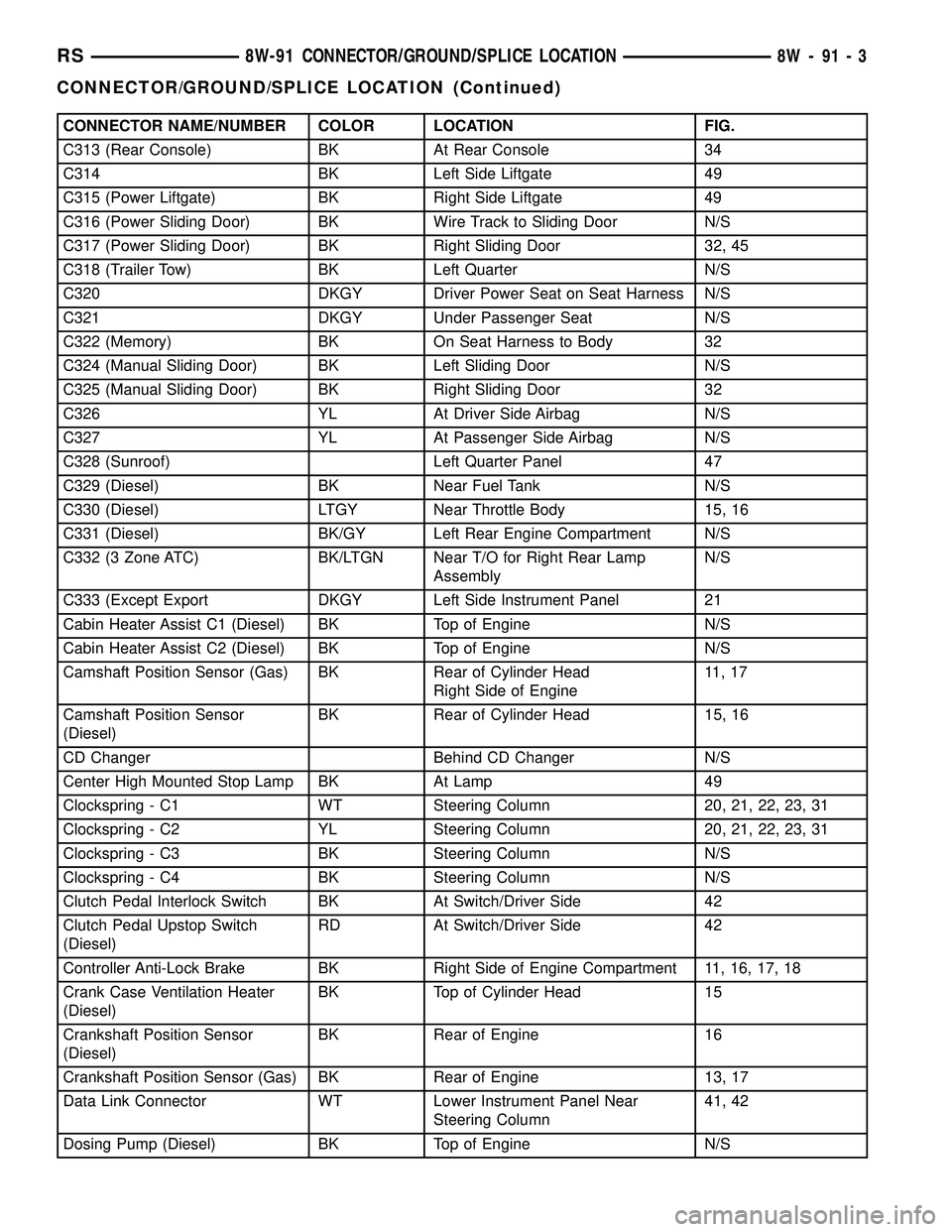
CONNECTOR NAME/NUMBER COLOR LOCATION FIG.
C313 (Rear Console) BK At Rear Console 34
C314 BK Left Side Liftgate 49
C315 (Power Liftgate) BK Right Side Liftgate 49
C316 (Power Sliding Door) BK Wire Track to Sliding Door N/S
C317 (Power Sliding Door) BK Right Sliding Door 32, 45
C318 (Trailer Tow) BK Left Quarter N/S
C320 DKGY Driver Power Seat on Seat Harness N/S
C321 DKGY Under Passenger Seat N/S
C322 (Memory) BK On Seat Harness to Body 32
C324 (Manual Sliding Door) BK Left Sliding Door N/S
C325 (Manual Sliding Door) BK Right Sliding Door 32
C326 YL At Driver Side Airbag N/S
C327 YL At Passenger Side Airbag N/S
C328 (Sunroof) Left Quarter Panel 47
C329 (Diesel) BK Near Fuel Tank N/S
C330 (Diesel) LTGY Near Throttle Body 15, 16
C331 (Diesel) BK/GY Left Rear Engine Compartment N/S
C332 (3 Zone ATC) BK/LTGN Near T/O for Right Rear Lamp
AssemblyN/S
C333 (Except Export DKGY Left Side Instrument Panel 21
Cabin Heater Assist C1 (Diesel) BK Top of Engine N/S
Cabin Heater Assist C2 (Diesel) BK Top of Engine N/S
Camshaft Position Sensor (Gas) BK Rear of Cylinder Head
Right Side of Engine11 , 1 7
Camshaft Position Sensor
(Diesel)BK Rear of Cylinder Head 15, 16
CD Changer Behind CD Changer N/S
Center High Mounted Stop Lamp BK At Lamp 49
Clockspring - C1 WT Steering Column 20, 21, 22, 23, 31
Clockspring - C2 YL Steering Column 20, 21, 22, 23, 31
Clockspring - C3 BK Steering Column N/S
Clockspring - C4 BK Steering Column N/S
Clutch Pedal Interlock Switch BK At Switch/Driver Side 42
Clutch Pedal Upstop Switch
(Diesel)RD At Switch/Driver Side 42
Controller Anti-Lock Brake BK Right Side of Engine Compartment 11, 16, 17, 18
Crank Case Ventilation Heater
(Diesel)BK Top of Cylinder Head 15
Crankshaft Position Sensor
(Diesel)BK Rear of Engine 16
Crankshaft Position Sensor (Gas) BK Rear of Engine 13, 17
Data Link Connector WT Lower Instrument Panel Near
Steering Column41, 42
Dosing Pump (Diesel) BK Top of Engine N/S
RS8W-91 CONNECTOR/GROUND/SPLICE LOCATION8W-91-3
CONNECTOR/GROUND/SPLICE LOCATION (Continued)
Page 2122 of 2585
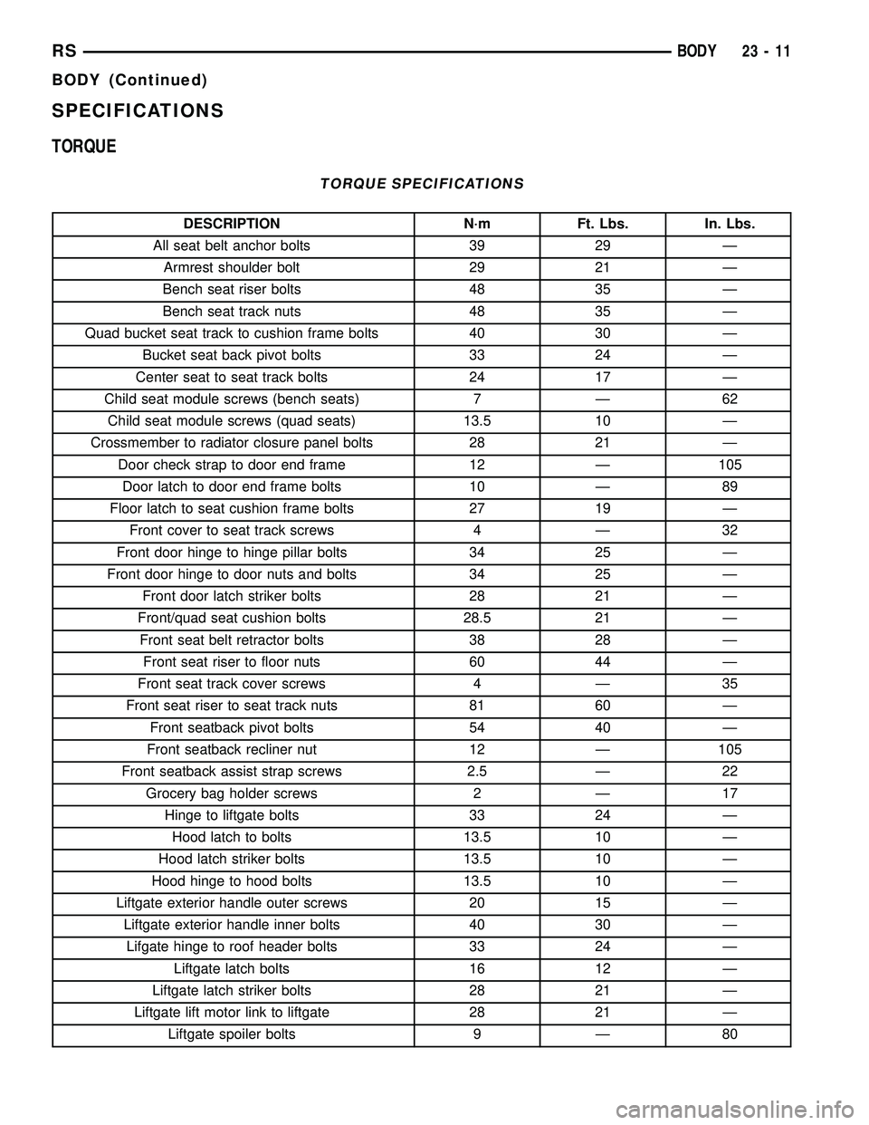
SPECIFICATIONS
TORQUE
TORQUE SPECIFICATIONS
DESCRIPTION N´m Ft. Lbs. In. Lbs.
All seat belt anchor bolts 39 29 Ð
Armrest shoulder bolt 29 21 Ð
Bench seat riser bolts 48 35 Ð
Bench seat track nuts 48 35 Ð
Quad bucket seat track to cushion frame bolts 40 30 Ð
Bucket seat back pivot bolts 33 24 Ð
Center seat to seat track bolts 24 17 Ð
Child seat module screws (bench seats) 7 Ð 62
Child seat module screws (quad seats) 13.5 10 Ð
Crossmember to radiator closure panel bolts 28 21 Ð
Door check strap to door end frame 12 Ð 105
Door latch to door end frame bolts 10 Ð 89
Floor latch to seat cushion frame bolts 27 19 Ð
Front cover to seat track screws 4 Ð 32
Front door hinge to hinge pillar bolts 34 25 Ð
Front door hinge to door nuts and bolts 34 25 Ð
Front door latch striker bolts 28 21 Ð
Front/quad seat cushion bolts 28.5 21 Ð
Front seat belt retractor bolts 38 28 Ð
Front seat riser to floor nuts 60 44 Ð
Front seat track cover screws 4 Ð 35
Front seat riser to seat track nuts 81 60 Ð
Front seatback pivot bolts 54 40 Ð
Front seatback recliner nut 12 Ð 105
Front seatback assist strap screws 2.5 Ð 22
Grocery bag holder screws 2 Ð 17
Hinge to liftgate bolts 33 24 Ð
Hood latch to bolts 13.5 10 Ð
Hood latch striker bolts 13.5 10 Ð
Hood hinge to hood bolts 13.5 10 Ð
Liftgate exterior handle outer screws 20 15 Ð
Liftgate exterior handle inner bolts 40 30 Ð
Lifgate hinge to roof header bolts 33 24 Ð
Liftgate latch bolts 16 12 Ð
Liftgate latch striker bolts 28 21 Ð
Liftgate lift motor link to liftgate 28 21 Ð
Liftgate spoiler bolts 9 Ð 80
RSBODY23-11
BODY (Continued)
Page 2123 of 2585
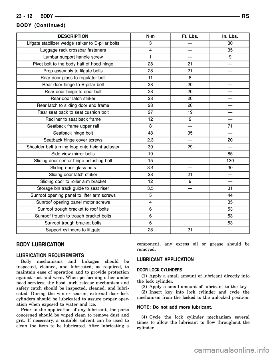
DESCRIPTION N´m Ft. Lbs. In. Lbs.
Lifgate stabilizer wedge striker to D-pillar bolts 3 Ð 30
Luggage rack crossbar fasteners 4 Ð 35
Lumbar support handle screw 1 Ð 9
Pivot bolt to the body half of hood hinge 28 21 Ð
Prop assembly to lifgate bolts 28 21 Ð
Rear door glass to regulator bolt 11 8 Ð
Rear door hinge to B-pillar bolt 28 20 Ð
Rear door hinge to door bolt 28 20 Ð
Rear door latch striker 28 20 Ð
Rear latch to sliding door end frame 28 20 Ð
Rear seat back to seat cushion bolt 27 19 Ð
Recliner to seat back frame 12 9 Ð
Seatback frame upper rail 8 Ð 71
Seatback hinge bolt 48 35 Ð
Seatback hinge cover screws 2.3 Ð 20
Shoulder belt turning loop onto height adjuster 39 29 Ð
Side view mirror bolts 10 Ð 85
Sliding door center hinge adjusting bolt 15 Ð 130
Sliding door glass nuts 3.4 Ð 30
Sliding door latch striker 28 21 Ð
Sliding door to roller arm bracket 12 9 Ð
Storage bin track guide to seat riser 3.5 Ð 31
Sunroof opening panel to lifter arm screws 5 44
Sunroof opening panel motor screws 4 35
Sunroof trough bracket to roof bolts 6 53
Sunroof trough to trough bracket bolts 6 53
Sunroof trough bracket bolts 6 53
Support cylinders to liftgate 28 21 Ð
BODY LUBRICATION
LUBRICATION REQUIREMENTS
Body mechanisms and linkages should be
inspected, cleaned, and lubricated, as required, to
maintain ease of operation and to provide protection
against rust and wear. When performing other under
hood services, the hood latch release mechanism and
safety catch should be inspected, cleaned, and lubri-
cated. During the winter season, external door lock
cylinders should be lubricated to assure proper oper-
ation when exposed to water and ice.
Prior to the application of any lubricant, the parts
concerned should be wiped clean to remove dust and
grit. If necessary, a suitable solvent can be used to
clean the item to be lubricated. After lubricating acomponent, any excess oil or grease should be
removed.LUBRICANT APPLICATION
DOOR LOCK CYLINDERS
(1) Apply a small amount of lubricant directly into
the lock cylinder.
(2) Apply a small amount of lubricant to the key.
(3) Insert key into lock cylinder and cycle the
mechanism from the locked to the unlocked position.
NOTE: Do not add more lubricant.
(4) Cycle the lock cylinder mechanism several
times to allow the lubricant to flow throughout the
cylinder.
23 - 12 BODYRS
BODY (Continued)
Page 2142 of 2585
point must not affect alignment. Striker should go
straight into the latching mechanism.
(2) On vehicles with left sliding doors, check the
fuel door blocker striker entry into latch. Striker at
this point must not affect alignment.
(3) Check C-post and B-post for door to aperture
gaps and door to door gaps. All gaps should be 5 mm
1 mm.
(4) Check door for height using character lines as
a reference. Also check roof contour as a controlling
factor.
Using the procedures noted below, adjust the side
door in the order the individual steps are called out.
DOOR FLUSHNESS ADJUSTMENT
(1) Check sliding door flushness at the C-pillar
striker.
(2) If the sliding door is under or over flush,
remove striker assembly and move thread plate over
keeping one bolt in plate so it will not fall between
inner and outer panels.
(3) Adjust the C-pillar striker in or out until the
door is flush. Then, the on size hole can be elongated
in the direction required. This can be done by grind-
ing or filing the sheet metal and then painting raw
edge to prevent rusting.
(4) Check upper B-pillar flushness to A-pillar
cover.
(5) The sliding door upper hinge can only be
moved outboard by addinga1mmshim behind the
hinge mounting area once the too attachment bolts
are removed and reinstalled.
(6) Check flushness at upper C-pillar.
(7) If upper C-pillar flushness is out of specifica-
tion use a heavy rubber mallet on the door assembly
until door is in specifications.
DOOR GAP ADJUSTMENT - UP/DOWN
(1) Visually inspect the sliding door for fitting low
at the top of the door by checking the alignment of
the top contour of the door to the quarter panel.
(2) Fully open the sliding door.
(3) Verify that all center hinge bolts are tight.
(4) Adjust the rear of the sliding door up by turn-
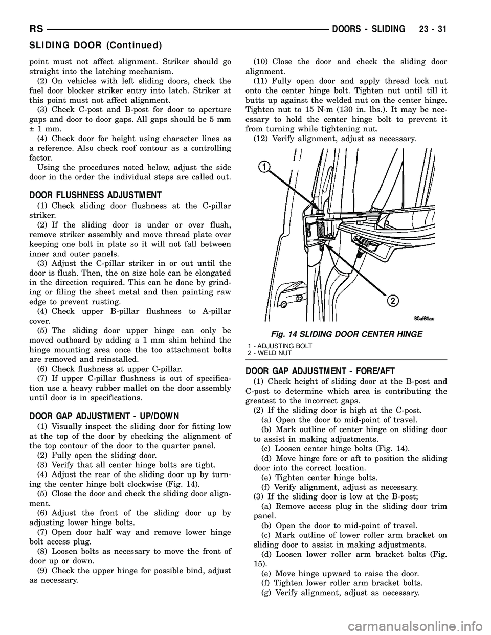
ing the center hinge bolt clockwise (Fig. 14).
(5) Close the door and check the sliding door align-
ment.
(6) Adjust the front of the sliding door up by
adjusting lower hinge bolts.
(7) Open door half way and remove lower hinge
bolt access plug.
(8) Loosen bolts as necessary to move the front of
door up or down.
(9) Check the upper hinge for possible bind, adjust
as necessary.(10) Close the door and check the sliding door
alignment.
(11) Fully open door and apply thread lock nut
onto the center hinge bolt. Tighten nut until till it
butts up against the welded nut on the center hinge.
Tighten nut to 15 N´m (130 in. lbs.). It may be nec-
essary to hold the center hinge bolt to prevent it
from turning while tightening nut.
(12) Verify alignment, adjust as necessary.
DOOR GAP ADJUSTMENT - FORE/AFT
(1) Check height of sliding door at the B-post and
C-post to determine which area is contributing the
greatest to the incorrect gaps.
(2) If the sliding door is high at the C-post.
(a) Open the door to mid-point of travel.
(b) Mark outline of center hinge on sliding door
to assist in making adjustments.
(c) Loosen center hinge bolts (Fig. 14).
(d) Move hinge fore or aft to position the sliding
door into the correct location.
(e) Tighten center hinge bolts.
(f) Verify alignment, adjust as necessary.
(3) If the sliding door is low at the B-post;
(a) Remove access plug in the sliding door trim
panel.
(b) Open the door to mid-point of travel.
(c) Mark outline of lower roller arm bracket on
sliding door to assist in making adjustments.
(d) Loosen lower roller arm bracket bolts (Fig.
15).
(e) Move hinge upward to raise the door.
(f) Tighten lower roller arm bracket bolts.
(g) Verify alignment, adjust as necessary.
Fig. 14 SLIDING DOOR CENTER HINGE
1 - ADJUSTING BOLT
2 - WELD NUT
RSDOORS - SLIDING23-31
SLIDING DOOR (Continued)
Page 2147 of 2585
(6) Verify sliding door operation. Adjust as neces-
sary.
(7) Place the watershield into position and press
securely to adhesive making sure to properly route
wiring and linkages.
(8) Install sliding door stop bumper. (Refer to 23 -
BODY/DOORS - SLIDING/STOP BUMPER -
INSTALLATION)
(9) Install sliding door trim panel. (Refer to 23 -
BODY/DOORS - SLIDING/TRIM PANEL - INSTAL-
LATION)
UPPER HINGE
REMOVAL
(1) Open sliding door, do not latch open.
(2) Remove screw attaching upper stop bracket to
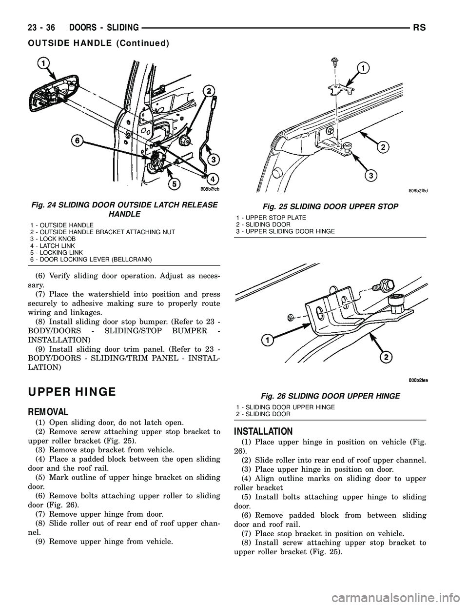
upper roller bracket (Fig. 25).
(3) Remove stop bracket from vehicle.
(4) Place a padded block between the open sliding
door and the roof rail.
(5) Mark outline of upper hinge bracket on sliding
door.
(6) Remove bolts attaching upper roller to sliding
door (Fig. 26).
(7) Remove upper hinge from door.
(8) Slide roller out of rear end of roof upper chan-
nel.
(9) Remove upper hinge from vehicle.
INSTALLATION
(1) Place upper hinge in position on vehicle (Fig.
26).
(2) Slide roller into rear end of roof upper channel.
(3) Place upper hinge in position on door.
(4) Align outline marks on sliding door to upper
roller bracket
(5) Install bolts attaching upper hinge to sliding
door.
(6) Remove padded block from between sliding
door and roof rail.
(7) Place stop bracket in position on vehicle.
(8) Install screw attaching upper stop bracket to
upper roller bracket (Fig. 25).
Fig. 24 SLIDING DOOR OUTSIDE LATCH RELEASE
HANDLE
1 - OUTSIDE HANDLE
2 - OUTSIDE HANDLE BRACKET ATTACHING NUT
3 - LOCK KNOB
4 - LATCH LINK
5 - LOCKING LINK
6 - DOOR LOCKING LEVER (BELLCRANK)
Fig. 25 SLIDING DOOR UPPER STOP
1 - UPPER STOP PLATE
2 - SLIDING DOOR
3 - UPPER SLIDING DOOR HINGE
Fig. 26 SLIDING DOOR UPPER HINGE
1 - SLIDING DOOR UPPER HINGE
2 - SLIDING DOOR
23 - 36 DOORS - SLIDINGRS
OUTSIDE HANDLE (Continued)
Page 2156 of 2585
EXTERIOR
TABLE OF CONTENTS
page page
BODY SIDE MOLDINGS
REMOVAL.............................45
INSTALLATION.........................46
COWL GRILLE
REMOVAL.............................50
INSTALLATION.........................51
EXTERIOR NAME PLATES - TAPE ATTACHED
REMOVAL.............................51
INSTALLATION.........................51
EXTERIOR NAME PLATES - ADHESIVE
ATTACHED
REMOVAL.............................51
INSTALLATION.........................51
FRONT FENDER
REMOVAL.............................52
INSTALLATION.........................52
FUEL FILL DOOR
REMOVAL.............................52
INSTALLATION.........................52
FUEL FILL DOOR BLOCKER LATCH
REMOVAL.............................53
INSTALLATION.........................53
FUEL FILL DOOR BLOCKER LATCH STRIKER
REMOVAL.............................53
INSTALLATION.........................53
FUEL FILL DOOR BLOCKER LOCKOUT LINK
REMOVAL.............................53INSTALLATION.........................54
GRILLE OPENING REINFORCEMENT
REMOVAL.............................54
INSTALLATION.........................54
FRONT WHEELHOUSE SPLASH SHIELD
REMOVAL.............................55
INSTALLATION.........................55
LUGGAGE RACK RISER
REMOVAL.............................55
INSTALLATION.........................56
LUGGAGE RACK CROSSBAR
REMOVAL.............................56
INSTALLATION.........................57
REAR QUARTER PANEL/FENDER AIR
EXHAUSTER
DESCRIPTION.........................57
REMOVAL.............................57
INSTALLATION.........................58
ROOF JOINT MOLDING
REMOVAL.............................58
INSTALLATION.........................58
SIDE VIEW MIRROR
REMOVAL.............................59
INSTALLATION.........................59
SIDE VIEW MIRROR GLASS
REMOVAL.............................59
INSTALLATION.........................59
BODY SIDE MOLDINGS
REMOVAL
Refer to (Fig. 1), (Fig. 2), (Fig. 3), (Fig. 4) or (Fig.
5)for proper location of fasteners holding the molding
to the wheelhouse lip and rocker panels.
(1) Warm the affected stick on molding and body
metal to approximately 38É C (100É F) using a suit-
able heat lamp or heat gun.
(2) If equipped, remove pop rivets holding molding
edge to wheelhouse lip.(3) Pull stick on molding from painted surface.
(4) Remove adhesive tape residue from painted
surface of vehicle. Use a 3M Scotch-BriteŸ Molding
Adhesive and Stripe Removal Disc, or equivalent, to
clean adhesive residue from painted surfaces. These
products are available from automotive paint suppli-
ers. Refer to instructions supplied with the specific
product for proper usage.
RSEXTERIOR23-45