2004 DODGE TOWN AND COUNTRY steering
[x] Cancel search: steeringPage 1240 of 2585
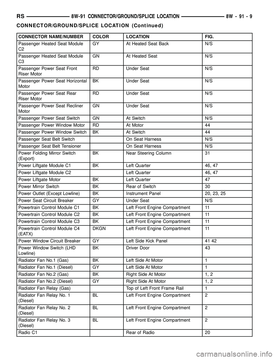
CONNECTOR NAME/NUMBER COLOR LOCATION FIG.
Passenger Heated Seat Module
C2GY At Heated Seat Back N/S
Passenger Heated Seat Module
C3GN At Heated Seat N/S
Passenger Power Seat Front
Riser MotorRD Under Seat N/S
Passenger Power Seat Horizontal
MotorBK Under Seat N/S
Passenger Power Seat Rear
Riser MotorRD Under Seat N/S
Passenger Power Seat Recliner
MotorGN Under Seat N/S
Passenger Power Seat Switch GN At Switch N/S
Passenger Power Window Motor RD At Motor 44
Passenger Power Window Switch BK At Switch 44
Passenger Seat Belt Switch On Seat Harness N/S
Passenger Seat Belt Tensioner On Seat Harness N/S
Power Folding Mirror Switch
(Export)BK Near Steering Column 31
Power Liftgate Module C1 BK Left Quarter 46, 47
Power Liftgate Module C2 Left Quarter 46, 47
Power Liftgate Motor BK Left Quarter 47
Power Mirror Switch BK Rear of Switch 30
Power Outlet (Except Lowline) BK Instrument Panel 20, 23, 25
Power Seat Circuit Breaker GY Under Seat N/S
Powertrain Control Module C1 BK Left Front Engine Compartment 11
Powertrain Control Module C2 BK Left Front Engine Compartment 11
Powertrain Control Module C3 BK Left Front Engine Compartment 11
Powertrain Control Module C4
(EATX)DKGN Left Front Engine Compartment 11
Power Window Circuit Breaker GY Left Side Kick Panel 41 42
Power Window Switch (LHD
Lowline)BK Driver Door 43
Radiator Fan No.1 (Gas) BK Left Side At Motor 1
Radiator Fan No.1 (Diesel) GY Left Side At Motor 1
Radiator Fan No.2 (Gas) BK Right Side At Motor 1, 2
Radiator Fan No.2 (Diesel) GY Right Side At Motor 1, 2
Radiator Fan Relay (Gas) Top of Left Front Frame Rail 1
Radiator Fan Relay No. 1
(Diesel)BL Left Front Engine Compartment 2
Radiator Fan Relay No. 2
(Diesel)BL Left Front Engine Compartment 2
Radiator Fan Relay No. 3
(Diesel)BL Left Front Engine Compartment 2
Radio C1 Rear of Radio 20
RS8W-91 CONNECTOR/GROUND/SPLICE LOCATION8W-91-9
CONNECTOR/GROUND/SPLICE LOCATION (Continued)
Page 1242 of 2585
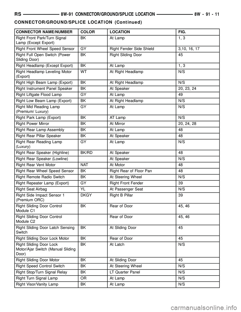
CONNECTOR NAME/NUMBER COLOR LOCATION FIG.
Right Front Park/Turn Signal
Lamp (Except Export)BK At Lamp 1, 3
Right Front Wheel Speed Sensor GY Right Fender Side Shield 3,10, 16, 17
Right Full Open Switch (Power
Sliding Door)BK Right Sliding Door 45
Right Headlamp (Except Export) BK At Lamp 1, 3
Right Headlamp Leveling Motor
(Export)WT At Right Headlamp N/S
Right High Beam Lamp (Export) BK At Right Headlamp N/S
Right Instrument Panel Speaker BK At Speaker 20, 23, 24
Right Liftgate Flood Lamp GY At Lamp 49
Right Low Beam Lamp (Export) BK At Right Headlamp N/S
Right Mid Reading Lamp
(Premium/ Luxury)GY At Lamp N/S
Right Park Lamp (Export) BK AT Lamp N/S
Right Power Mirror BK At Mirror 20, 24, 28
Right Rear Lamp Assembly BK At Lamp 48
Right Rear Pillar Speaker BK At Speaker 48
Right Rear Reading Lamp
(Luxury)GY At Lamp N/S
Right Rear Speaker (Highline) BK/RD At Speaker 48
Right Rear Speaker (Lowline) At Speaker N/S
Right Rear Vent Motor NAT At Motor 48
Right Rear Wheel Speed Sensor BK Right Rear of Floor Pan 48
Right Remote Radio Switch BK At Steering Wheel N/S
Right Repeater Lamp (Export) GY Right Front Fender 39
Right Seat Airbag YL At Passenger Seat N/S
Right Side Impact Sensor 1
(Premium ORC)DKGY Right B Pillar 39
Right Sliding Door Control
Module C1BK Rear of Door 45, 46
Right Sliding Door Control
Module C2Rear of Door 45, 46
Right Sliding Door Latch Sensing
SwitchBK At Sliding Door 45
Right Sliding Door Lock Motor BK Rear of Door 45
Right Sliding Door Lock
Motor/Ajar Switch (Manual Sliding
Door)BK At Latch N/S
Right Sliding Door Motor BK At Sliding Door 45
Right Speed Control Switch BK At Steering Wheel N/S
Right Stop/Turn Signal Relay BK LT Quarter Panel N/S
Right Turn Signal Lamp OR At Lamp N/S
Right Visor/Vanity Lamp BK At Lamp N/S
RS8W-91 CONNECTOR/GROUND/SPLICE LOCATION8W-91-11
CONNECTOR/GROUND/SPLICE LOCATION (Continued)
Page 1243 of 2585
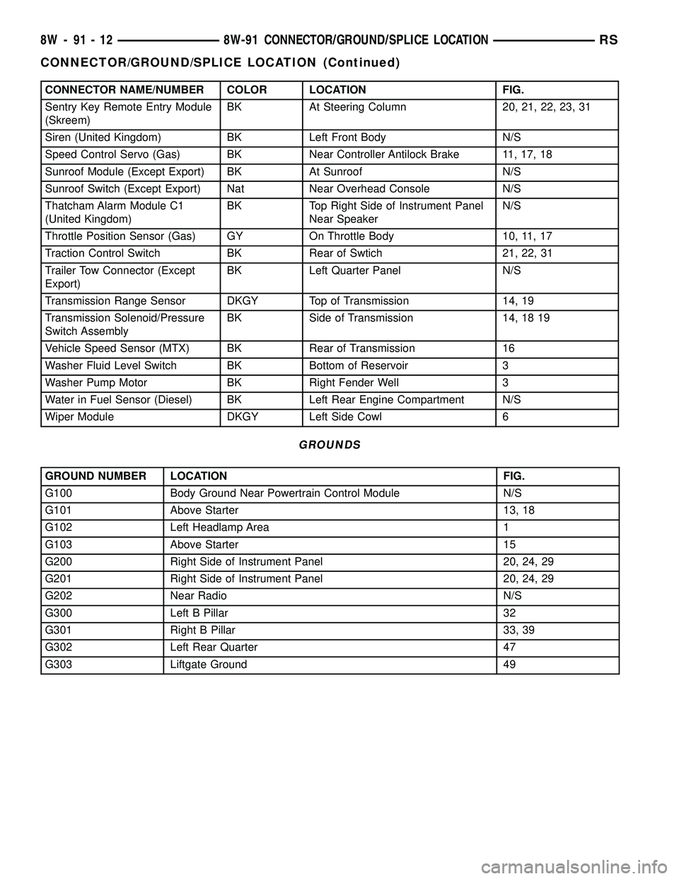
CONNECTOR NAME/NUMBER COLOR LOCATION FIG.
Sentry Key Remote Entry Module
(Skreem)BK At Steering Column 20, 21, 22, 23, 31
Siren (United Kingdom) BK Left Front Body N/S
Speed Control Servo (Gas) BK Near Controller Antilock Brake 11, 17, 18
Sunroof Module (Except Export) BK At Sunroof N/S
Sunroof Switch (Except Export) Nat Near Overhead Console N/S
Thatcham Alarm Module C1
(United Kingdom)BK Top Right Side of Instrument Panel
Near SpeakerN/S
Throttle Position Sensor (Gas) GY On Throttle Body 10, 11, 17
Traction Control Switch BK Rear of Swtich 21, 22, 31
Trailer Tow Connector (Except
Export)BK Left Quarter Panel N/S
Transmission Range Sensor DKGY Top of Transmission 14, 19
Transmission Solenoid/Pressure
Switch AssemblyBK Side of Transmission 14, 18 19
Vehicle Speed Sensor (MTX) BK Rear of Transmission 16
Washer Fluid Level Switch BK Bottom of Reservoir 3
Washer Pump Motor BK Right Fender Well 3
Water in Fuel Sensor (Diesel) BK Left Rear Engine Compartment N/S
Wiper Module DKGY Left Side Cowl 6
GROUNDS
GROUND NUMBER LOCATION FIG.
G100 Body Ground Near Powertrain Control Module N/S
G101 Above Starter 13, 18
G102 Left Headlamp Area 1
G103 Above Starter 15
G200 Right Side of Instrument Panel 20, 24, 29
G201 Right Side of Instrument Panel 20, 24, 29
G202 Near Radio N/S
G300 Left B Pillar 32
G301 Right B Pillar 33, 39
G302 Left Rear Quarter 47
G303 Liftgate Ground 49
8W - 91 - 12 8W-91 CONNECTOR/GROUND/SPLICE LOCATIONRS
CONNECTOR/GROUND/SPLICE LOCATION (Continued)
Page 1245 of 2585
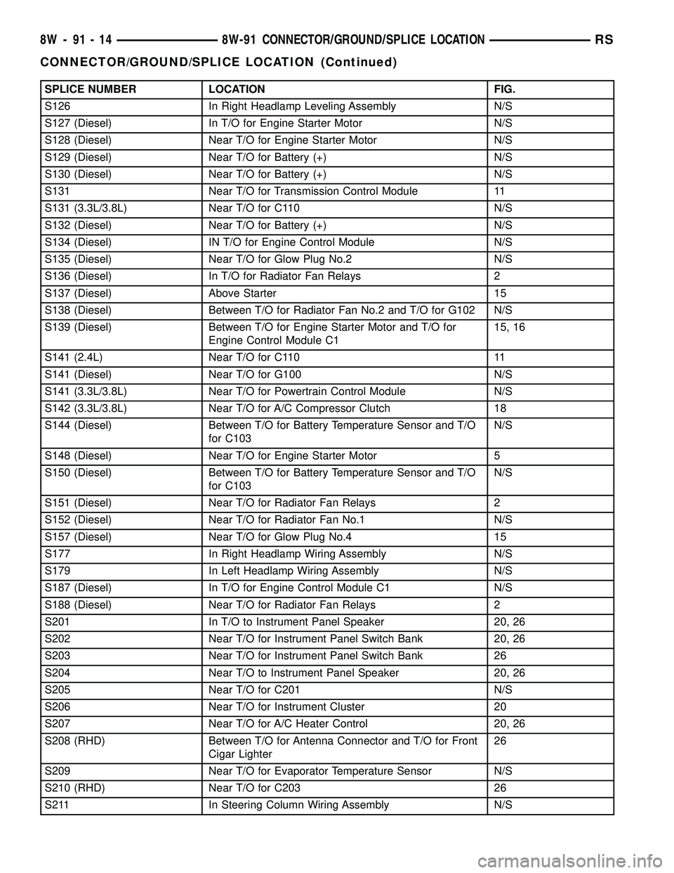
SPLICE NUMBER LOCATION FIG.
S126 In Right Headlamp Leveling Assembly N/S
S127 (Diesel) In T/O for Engine Starter Motor N/S
S128 (Diesel) Near T/O for Engine Starter Motor N/S
S129 (Diesel) Near T/O for Battery (+) N/S
S130 (Diesel) Near T/O for Battery (+) N/S
S131 Near T/O for Transmission Control Module 11
S131 (3.3L/3.8L) Near T/O for C110 N/S
S132 (Diesel) Near T/O for Battery (+) N/S
S134 (Diesel) IN T/O for Engine Control Module N/S
S135 (Diesel) Near T/O for Glow Plug No.2 N/S
S136 (Diesel) In T/O for Radiator Fan Relays 2
S137 (Diesel) Above Starter 15
S138 (Diesel) Between T/O for Radiator Fan No.2 and T/O for G102 N/S
S139 (Diesel) Between T/O for Engine Starter Motor and T/O for
Engine Control Module C115, 16
S141 (2.4L) Near T/O for C110 11
S141 (Diesel) Near T/O for G100 N/S
S141 (3.3L/3.8L) Near T/O for Powertrain Control Module N/S
S142 (3.3L/3.8L) Near T/O for A/C Compressor Clutch 18
S144 (Diesel) Between T/O for Battery Temperature Sensor and T/O
for C103N/S
S148 (Diesel) Near T/O for Engine Starter Motor 5
S150 (Diesel) Between T/O for Battery Temperature Sensor and T/O
for C103N/S
S151 (Diesel) Near T/O for Radiator Fan Relays 2
S152 (Diesel) Near T/O for Radiator Fan No.1 N/S
S157 (Diesel) Near T/O for Glow Plug No.4 15
S177 In Right Headlamp Wiring Assembly N/S
S179 In Left Headlamp Wiring Assembly N/S
S187 (Diesel) In T/O for Engine Control Module C1 N/S
S188 (Diesel) Near T/O for Radiator Fan Relays 2
S201 In T/O to Instrument Panel Speaker 20, 26
S202 Near T/O for Instrument Panel Switch Bank 20, 26
S203 Near T/O for Instrument Panel Switch Bank 26
S204 Near T/O to Instrument Panel Speaker 20, 26
S205 Near T/O for C201 N/S
S206 Near T/O for Instrument Cluster 20
S207 Near T/O for A/C Heater Control 20, 26
S208 (RHD) Between T/O for Antenna Connector and T/O for Front
Cigar Lighter26
S209 Near T/O for Evaporator Temperature Sensor N/S
S210 (RHD) Near T/O for C203 26
S211 In Steering Column Wiring Assembly N/S
8W - 91 - 14 8W-91 CONNECTOR/GROUND/SPLICE LOCATIONRS
CONNECTOR/GROUND/SPLICE LOCATION (Continued)
Page 1246 of 2585
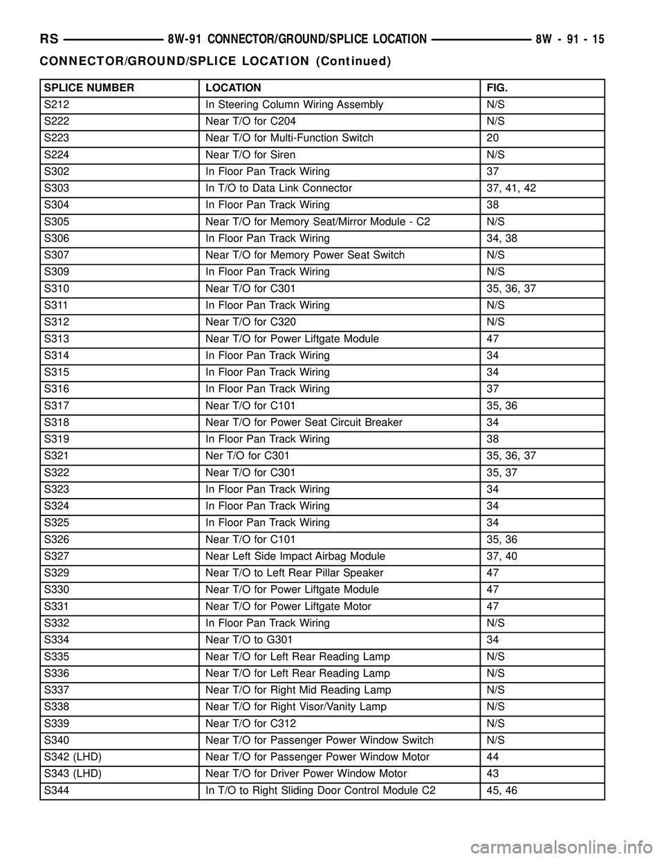
SPLICE NUMBER LOCATION FIG.
S212 In Steering Column Wiring Assembly N/S
S222 Near T/O for C204 N/S
S223 Near T/O for Multi-Function Switch 20
S224 Near T/O for Siren N/S
S302 In Floor Pan Track Wiring 37
S303 In T/O to Data Link Connector 37, 41, 42
S304 In Floor Pan Track Wiring 38
S305 Near T/O for Memory Seat/Mirror Module - C2 N/S
S306 In Floor Pan Track Wiring 34, 38
S307 Near T/O for Memory Power Seat Switch N/S
S309 In Floor Pan Track Wiring N/S
S310 Near T/O for C301 35, 36, 37
S311 In Floor Pan Track Wiring N/S
S312 Near T/O for C320 N/S
S313 Near T/O for Power Liftgate Module 47
S314 In Floor Pan Track Wiring 34
S315 In Floor Pan Track Wiring 34
S316 In Floor Pan Track Wiring 37
S317 Near T/O for C101 35, 36
S318 Near T/O for Power Seat Circuit Breaker 34
S319 In Floor Pan Track Wiring 38
S321 Ner T/O for C301 35, 36, 37
S322 Near T/O for C301 35, 37
S323 In Floor Pan Track Wiring 34
S324 In Floor Pan Track Wiring 34
S325 In Floor Pan Track Wiring 34
S326 Near T/O for C101 35, 36
S327 Near Left Side Impact Airbag Module 37, 40
S329 Near T/O to Left Rear Pillar Speaker 47
S330 Near T/O for Power Liftgate Module 47
S331 Near T/O for Power Liftgate Motor 47
S332 In Floor Pan Track Wiring N/S
S334 Near T/O to G301 34
S335 Near T/O for Left Rear Reading Lamp N/S
S336 Near T/O for Left Rear Reading Lamp N/S
S337 Near T/O for Right Mid Reading Lamp N/S
S338 Near T/O for Right Visor/Vanity Lamp N/S
S339 Near T/O for C312 N/S
S340 Near T/O for Passenger Power Window Switch N/S
S342 (LHD) Near T/O for Passenger Power Window Motor 44
S343 (LHD) Near T/O for Driver Power Window Motor 43
S344 In T/O to Right Sliding Door Control Module C2 45, 46
RS8W-91 CONNECTOR/GROUND/SPLICE LOCATION8W-91-15
CONNECTOR/GROUND/SPLICE LOCATION (Continued)
Page 1268 of 2585
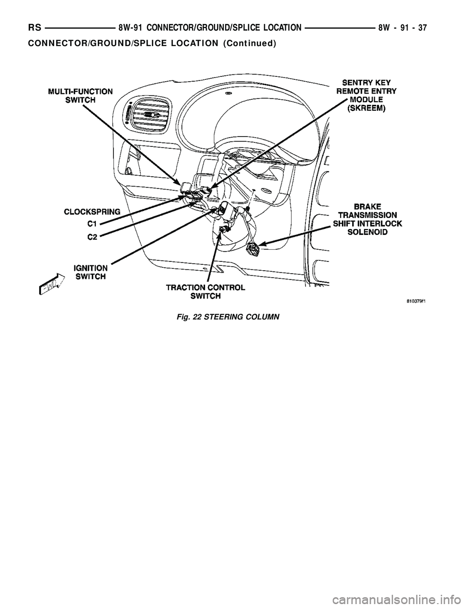
Fig. 22 STEERING COLUMN
RS8W-91 CONNECTOR/GROUND/SPLICE LOCATION8W-91-37
CONNECTOR/GROUND/SPLICE LOCATION (Continued)
Page 1274 of 2585
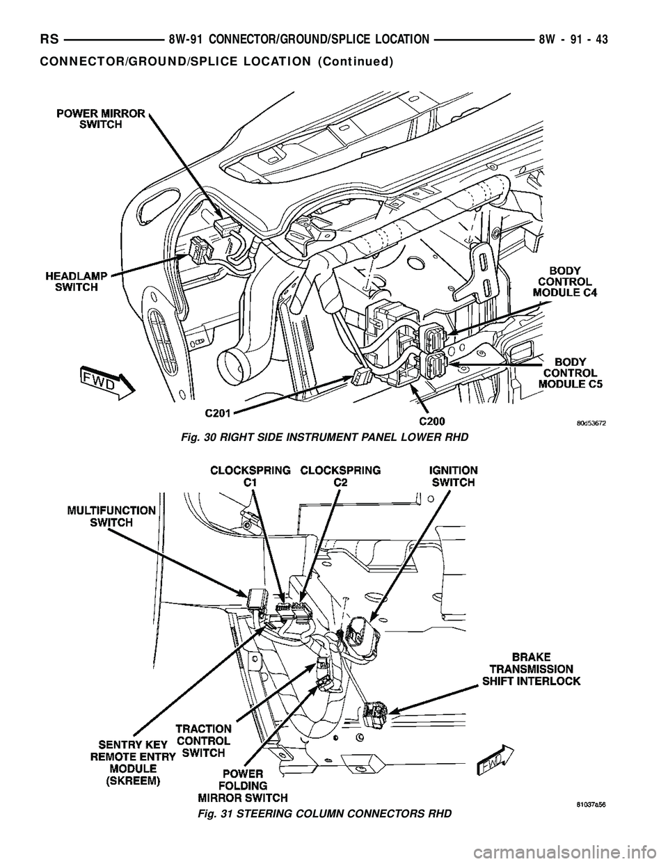
Fig. 30 RIGHT SIDE INSTRUMENT PANEL LOWER RHD
Fig. 31 STEERING COLUMN CONNECTORS RHD
RS8W-91 CONNECTOR/GROUND/SPLICE LOCATION8W-91-43
CONNECTOR/GROUND/SPLICE LOCATION (Continued)
Page 1295 of 2585
POWER OUTLET
DESCRIPTION
Accessory power outlets are standard equipment on
this model. Two power outlets are installed in the
instrument panel center lower bezel, which is located
near the bottom of the instrument panel center stack
area. Two additional power outlets are also incorpo-
rated into the vehicle, one on the left rear C-pillar
trim and the other in the center console, if equipped.
The power outlets bases are secured by a snap fit in
the appropriate bezels. A hinged plug flips closed to
conceal and protect the power outlet base when the
power outlet is not being used.
The power outlet receptacle unit and the power
outlet plugs are each available for service replace-
ment.
OPERATION
The power outlet base or receptacle shell is con-
nected to ground, and an insulated contact in the
bottom of the shell is connected to battery current.
The power outlet on the instrument panel marked
with a battery receives battery voltage from a fuse in
the Integrated Power Module (IPM) at all times. The
other power outlet on the instrument panel marked
with a key receives battery voltage only when the
key is in the on position.
The power outlet located in the center console
receives battery voltage all the time when positioned
between thefront seatsand key-on voltage when
positioned between therear seats. The power outlet
located on the C-pillar receives battery voltage only
when the key is in the on position.
DIAGNOSIS AND TESTING
DIAGNOSIS & TESTING - POWER OUTLET
For complete circuit diagrams, refer toCigar
Lighter/Power Outletin Wiring Diagrams.
WARNING: ON VEHICLES EQUIPPED WITH AIR-
BAGS, REFER TO RESTRAINTS BEFORE ATTEMPT-
ING ANY STEERING WHEEL, STEERING COLUMN,
SEAT OR INSTRUMENT PANEL COMPONENT DIAG-
NOSIS OR SERVICE. FAILURE TO TAKE THE
PROPER PRECAUTIONS COULD RESULT IN ACCI-
DENTAL AIRBAG DEPLOYMENT AND POSSIBLE
PERSONAL INJURY.
(1) Check the fused B(+) fuse in the Integrated
Power Module (IPM). If OK, go to Step 2. If not OK,
repair the shorted circuit or component as required
and replace the faulty fuse.
(2) Check for battery voltage at the fused B(+) fuse
in the IPM. If OK, go to Step 3. If not OK, repair the
open fused B(+) circuit to the IPM fuse as required.
(3) Open the power outlet door. Check for continu-
ity between the inside circumference of the power
outlet receptacle and a good ground. There should be
continuity. If OK, go to Step 4. If not OK, go to Step
5.
(4) Check for battery voltage at the insulated con-
tact located at the back of the power outlet recepta-
cle. If not OK, go to Step 5.
(5) Disconnect and isolate the battery negative
cable. Remove the appropriate bezel. Check for conti-
nuity between the ground circuit cavity of the power
outlet wire harness connector and a good ground.
There should be continuity. If OK, go to Step 6. If not
OK, repair the open ground circuit to ground as
required.
(6) Connect the battery negative cable. Check for
battery voltage at the fused B(+) circuit cavity of the
power outlet wire harness connector. If OK, replace
the faulty power outlet receptacle. If not OK, repair
the open fused B(+) circuit to the IPM fuse as
required.
8W - 97 - 4 8W-97 POWER DISTRIBUTION SYSTEMRS