2004 DAEWOO NUBIRA safety belt
[x] Cancel search: safety beltPage 49 of 2643

1C1 – 6I1.4L/1.6L DOHC ENGINE MECHANICAL
DAEWOO V–121 BL4
Application Lb–InLb–Ft NSm
Oil Pump Bolts10–89
Oil Pump Rear Cover Bolts8–71
Oil Pump Retaining Bolts10–89
Oil Suction Pipe or Support Bracket Bolts10–89
Rear Timing Belt Cover Bolts10–89
Safety Relief Valve Bolt303022–
Spark Plugs2518–
Thermostat Housing Mounting Bolts2015–
Timing Belt Automatic Tensioner Bolts2518–
Timing Belt Idler Pulley Bolt4030–
Transaxle Bell Housing Bolts7555–
Transaxle Torque Converter Bolts4533–
Upper Front Timing Belt Cover Bolts10–89
Water Pump Retaining Bolts10–89
Page 125 of 2643

1.8L DOHC ENGINE MECHANICAL 1C2 – 5
DAEWOO V–121 BL4
Application Lb–InLb–Ft NSm
Oil Pan Retaining Bolts10–89
Oil Pressure Switch4030–
Oil Suction Pipe Bolts8–71
Oil Suction Pipe Support Bracket Bolts16–53
Oil Pump Rear Cover Bolts6–53
Oil Pump Retaining Bolts10–89
Pulse Pickup Sensor Disc1310–
Rear Timing Belt Cover Bolts7–62
Safety Relief Valve Bolt3022–
Spark Plug Cover Bolts8–71
Spark Plugs2015–
Thermostat Housing Mounting Bolts1511–
Throttle Cable Bracket Bolts8–71
Timing Belt Automatic Tensioner Bolts2518–
Timing Belt Idler Pulley Bolt2518–
Timing Belt Idler Pulley Nut2518–
Transaxle Bell Housing Bolts7555–
Transaxle Torque Converter Bolts6044–
Page 2104 of 2643

SEAT BELTS 8A – 9
DAEWOO V–121 BL4
GENERAL DESCRIPTION
AND SYSTEM OPERATION
DRIVER SEAT BELT WARNING
The driver’s safety belt incorporates a safety belt reminder
light in the instrument cluster to remind the driver if the
safety belt is not fastened when the the ignition is turned
ON.
THREE–POINT ELR FRONT SEAT
BELT WITH PRETENSIONER
The three–point emergency locking retractor (ELR) front
seat belt pretensioner is always unlocked, allowing the
passenger freedom of movement, except in emergencies
such as rapid deceleration, rapid acceleration, or hard cor-
nering maneuvers.
The front seat belt pretensioner contains an ignitor charge
and a gas generator to inflate the pretensioner. The pre-
tensioner also includes wiring and a connector. The con-
nector of the pretensioner contains a shorting bar which
short–circuits the pretensioner high circuit to the preten-
sioner low circuit when the connector is disconnected. The
shorting bar prevents current from traveling through the
pretensioner during servicing. The shorting bar disen-
gaged when the connecotr is connected.
The pretensioner is an electronically controlled pyrotech-
nical reactor which reduce seat belt slack when it is actived
with air bags.
The front seat belt pretensioner must be replaced after an
accident that cause its activation.
THREE–POINT CLR (ELR) REAR
OUTBOARD SEAT BELT
The rear outboard seating positions use the three–point
child locking retractor (CLR) or emergency locking retrac-
tor (ELR) seat belts. The three–point CLR (ELR) seat beltis always unlocked, allowing the passenger freedom of
movement, except in emergencies such as rapid decel-
eration, rapid acceleration, or hard cornering maneuvers.
OPERATIONAL AND FUNCTIONAL
CHECKS
CAUTION :
S Keep sharp objects and potentially damaging
objects away from the seat belts.
S Avoid bending or damaging any portion of the
buckle or the latch plate.
S Do not bleach or dye the belt webbing. Use
only mild soap and water in order to clean the
belts.
S When installing the seat belt anchor bolts and
the screws, start the bolts and the screws by
hand in order to prevent cross–threading.
S Do not attempt any repairs on the retractor
mechanisms or the covers. Replace any defec-
tive assemblies with new assemblies.
S Replace any belts that are cut or damaged in
any way.
1. Inspect all seat belt anchor bolts and the screws in
order to verify that they are secure.
2. Inspect the seat belt buckle. The buckle must lock
and unlock easily.
3. After inserting the latch into the buckle, tug sharply
on the belt. The buckle must remain locked.
4. Fully extend the shoulder belt portion to make sure
that there is no twisting or tears in the belt.
5. Let the shoulder belt retract fully. The belt should
retract easily.
CHILD SEAT TETHER ANCHOR
For notch back vehicle, there are three child seat tether
anchors located on the read deck lid sill plate. For hatch
back vehicle, there are three child seat fether anchors on
the lower rear tail member in the luggage compartment.
And there are 4 lower child anchors under the rear seat.
4 circular discs on the rear seat indicate the location of the
lower child anchors.
Page 2204 of 2643
8B – 100ISUPPLEMENTAL INFLATABLE RESTRAINTS (SIR)
DAEWOO V–121 BL4
GENERAL DESCRIPTION
AND SYSTEM OPERATION
SUPPLEMENTAL INFLATABLE
RESTRAINTS(SIR)
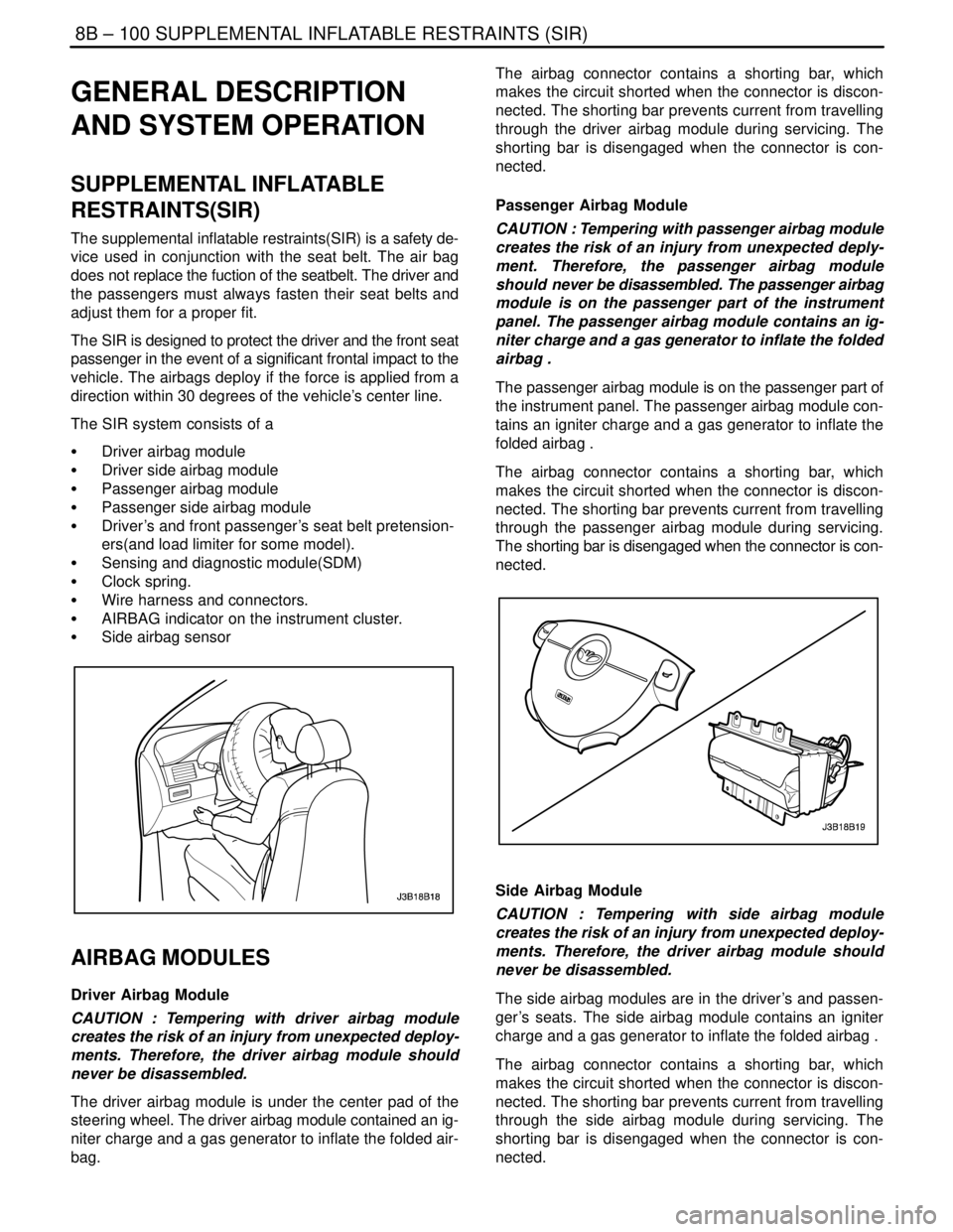
The supplemental inflatable restraints(SIR) is a safety de-
vice used in conjunction with the seat belt. The air bag
does not replace the fuction of the seatbelt. The driver and
the passengers must always fasten their seat belts and
adjust them for a proper fit.
The SIR is designed to protect the driver and the front seat
passenger in the event of a significant frontal impact to the
vehicle. The airbags deploy if the force is applied from a
direction within 30 degrees of the vehicle’s center line.
The SIR system consists of a
S Driver airbag module
S Driver side airbag module
S Passenger airbag module
S Passenger side airbag module
S Driver’s and front passenger’s seat belt pretension-
ers(and load limiter for some model).
S Sensing and diagnostic module(SDM)
S Clock spring.
S Wire harness and connectors.
S AIRBAG indicator on the instrument cluster.
S Side airbag sensor
AIRBAG MODULES
Driver Airbag Module
CAUTION : Tempering with driver airbag module
creates the risk of an injury from unexpected deploy-
ments. Therefore, the driver airbag module should
never be disassembled.
The driver airbag module is under the center pad of the
steering wheel. The driver airbag module contained an ig-
niter charge and a gas generator to inflate the folded air-
bag.The airbag connector contains a shorting bar, which
makes the circuit shorted when the connector is discon-
nected. The shorting bar prevents current from travelling
through the driver airbag module during servicing. The
shorting bar is disengaged when the connector is con-
nected.
Passenger Airbag Module
CAUTION : Tempering with passenger airbag module
creates the risk of an injury from unexpected deply-
ment. Therefore, the passenger airbag module
should never be disassembled. The passenger airbag
module is on the passenger part of the instrument
panel. The passenger airbag module contains an ig-
niter charge and a gas generator to inflate the folded
airbag .
The passenger airbag module is on the passenger part of
the instrument panel. The passenger airbag module con-
tains an igniter charge and a gas generator to inflate the
folded airbag .
The airbag connector contains a shorting bar, which
makes the circuit shorted when the connector is discon-
nected. The shorting bar prevents current from travelling
through the passenger airbag module during servicing.
The shorting bar is disengaged when the connector is con-
nected.
Side Airbag Module
CAUTION : Tempering with side airbag module
creates the risk of an injury from unexpected deploy-
ments. Therefore, the driver airbag module should
never be disassembled.
The side airbag modules are in the driver’s and passen-
ger’s seats. The side airbag module contains an igniter
charge and a gas generator to inflate the folded airbag .
The airbag connector contains a shorting bar, which
makes the circuit shorted when the connector is discon-
nected. The shorting bar prevents current from travelling
through the side airbag module during servicing. The
shorting bar is disengaged when the connector is con-
nected.
Page 2206 of 2643
8B – 102ISUPPLEMENTAL INFLATABLE RESTRAINTS (SIR)
DAEWOO V–121 BL4
spring should never be disassembled, and there is no
timekeeping function. The clock spring contains two or
three current–carrying coils. One of the current–carrying
coils maintains continuous contact within the driver de-
ployment loop while the steering wheel is rotated. The
clock spring also contains coils that maintain continuous
contact for horn and remote audio control switch circuit.
Turning the steering wheel in one direction tightens the
coil, and turning the steering wheel in the opposite direc-
tion loosens the coil. Do not turn the clock spring when the
steering wheel is not attached. Refer to ”Clock Spring” in
this section for proper installation of the clock spring.
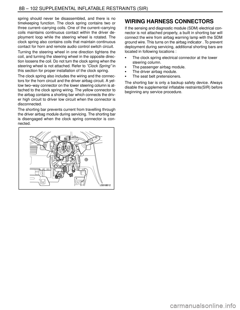
The clock spring also includes the wiring and the connec-
tors for the horn circuit and the driver airbag circuit. A yel-
low two–way connector on the lower steering column is at-
tached to the clock spring wiring. The yellow connector to
the airbag contains a shorting bar which connects the driv-
er high circuit to driver low circuit when the connector is
disconnected.
The shorting bar prevents current from travelling through
the driver airbag module during servicing. The shorting bar
is disengaged when the clock spring connector is con-
nected.WIRING HARNESS CONNECTORS
If the sensing and diagnostic module (SDM) electrical con-
nector is not attached properly, a built in shorting bar will
connect the wire from airbag warning lamp with the SDM
ground wire. This turns on the airbag indicator . To prevent
deployment during servicing, additional shorting bars are
located in following locations :
S The clock spring electrical connector at the lower
steering column.
S The passenger airbag module.
S The driver airbag module.
S The seat belt pretensioners.
The shorting bar is only a backup safety device. Always
disable the supplemental inflatable restraints(SIR) before
beginning any service procedure.
Page 2563 of 2643
NUBIRA/LACETTI ROOF, BACK PANEL AND REAR FLOOR PANEL 5–11
3–2. REPAIR PROCEDURE
1. Remove the related parts.
S Parts to be removed when removing the back panel.
S Rear seat belt and rear seat.
S Muffler, fuel tank and related parts.
S Chassis parts.
S Other related parts.
CAUTION : Do not smoke while working near the
fuel system. Keep open flame away from the fuel
system. If necessary, remove the fuel tank and off
lines.
2. Roughly pull out and straighten the damaged area.
S Check the damage and roughly pull out and re pair the
related back panel, side panel, wheel house inner, rear
longitudinal and other damaged parts with the frame
straightener before remov ing the extension rear floor
panel, rear floor pane and back panel.
S Attach the car to the frame straightener by tightening the
underbody clamps located at the jack up designated
points on the bottom of the frame door opening.
Note : Measure in reference to the dimensions on the
body repair chart.
3. Cut and pry off the back panel.
S The back panel to be cut and pried off when removing
the back panel.
4. Cut and pry off the rear floor and extension rear floor
panel.
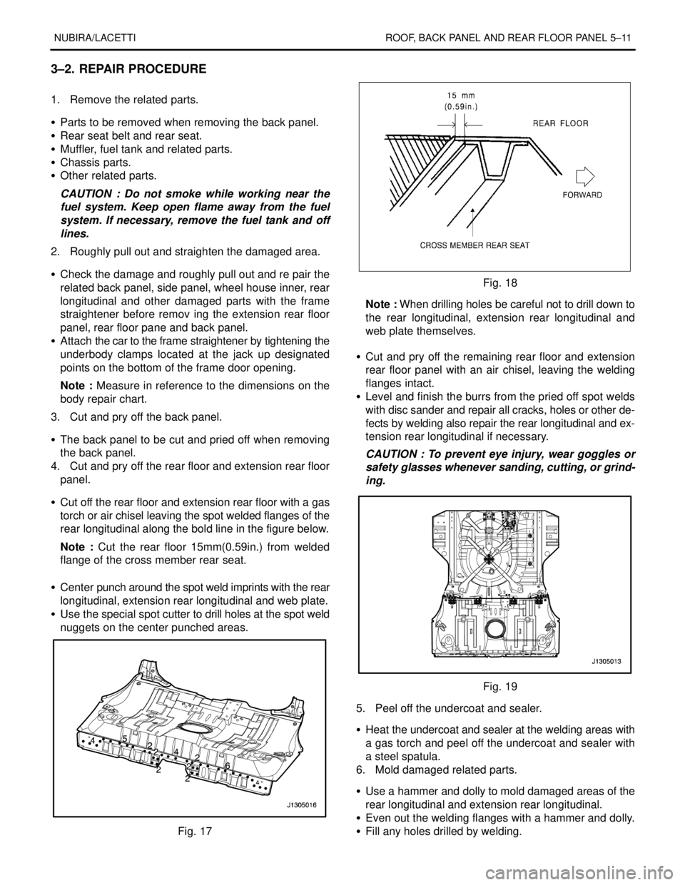
S Cut off the rear floor and extension rear floor with a gas
torch or air chisel leaving the spot welded flanges of the
rear longitudinal along the bold line in the figure below.
Note : Cut the rear floor 15mm(0.59in.) from welded
flange of the cross member rear seat.
S Center punch around the spot weld imprints with the rear
longitudinal, extension rear longitudinal and web plate.
S Use the special spot cutter to drill holes at the spot weld
nuggets on the center punched areas.
Fig. 17
Fig. 18
Note : When drilling holes be careful not to drill down to
the rear longitudinal, extension rear longitudinal and
web plate themselves.
S Cut and pry off the remaining rear floor and extension
rear floor panel with an air chisel, leaving the welding
flanges intact.
S Level and finish the burrs from the pried off spot welds
with disc sander and repair all cracks, holes or other de-
fects by welding also repair the rear longitudinal and ex-
tension rear longitudinal if necessary.
CAUTION : To prevent eye injury, wear goggles or
safety glasses whenever sanding, cutting, or grind-
ing.
Fig. 19
5. Peel off the undercoat and sealer.
S Heat the undercoat and sealer at the welding areas with
a gas torch and peel off the undercoat and sealer with
a steel spatula.
6. Mold damaged related parts.
S Use a hammer and dolly to mold damaged areas of the
rear longitudinal and extension rear longitudinal.
S Even out the welding flanges with a hammer and dolly.
S Fill any holes drilled by welding.
Page 2568 of 2643
NUBIRA/LACETTI FRAME DOOR OPENING, DOOR AND SIDE PANEL OUTER 6–3
1–2. REPAIR PROCEDURE
1. Remove the related parts.
S Doors.
S Weather strips, pillar trims and related parts.
S Carpet.
S Seat belt assembly
S Door switch and wiring harness.
S Fuel pipe and brake oil pipe.
S Other related parts.
Note : Pull out and straighten the damaged area to
approximately the original shape.
2. Remove the related parts.
S Damage may extend to the inner roof frame, the inner
frame door opening and the floor. Determine the extent
of the damage first, so the frame can be pulled out prop-
erly.
Note : Use heat–resistant protective cover for protect
painting areas, seats, carpets and other parts.
S Pull out and straighten the damaged areas.
S Do not pull out more than necessary.
3. Cut and pry off the frame door opening.
S Check the damage on the frame door opening, then cut
the new frame door opening so it will overlap by
30mm(1.18in.) in the pillar, front and rear.
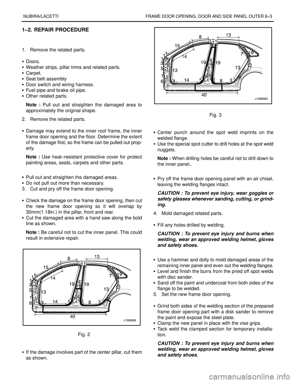
S Cut the damaged area with a hand saw along the bold
line as shown.
Note : Be careful not to cut the inner panel. This could
result in extensive repair.
Fig. 2
S If the damage involves part of the center pillar, cut them
as shown.
Fig. 3
S Center punch around the spot weld imprints on the
welded flange.
S Use the special spot cutter to drill holes at the spot weld
nuggets.
Note : When drilling holes be careful not to drill down to
the inner panel..
S Pry off the frame door opening panel with an air chisel,
leaving the welding flanges intact.
CAUTION : To prevent eye injury, wear goggles or
safety glasses whenever sanding, cutting, or grind-
ing.
4. Mold damaged related parts.
S Fill any holes drilled by welding.
CAUTION : To prevent eye injury and burns when
welding, wear an approved welding helmet, gloves
and safety shoes.
S Use a hammer and dolly to mold damaged areas of the
remaining inner panel and even out the welding flanges.
S Level and finish the burrs from the pried off spot welds
with disc sander.
S Sand off the paint and undercoat from both sides of the
flange to be welded.
5. Set the new frame door opening.
S Grind both sides of the welding section of the prepared
frame door opening part with a disk sander to remove
the paint and expose the steel plate.
S Clamp the new panel in place with the vise grips.
S Tack weld the clamped section for temporary installa-
tion.
CAUTION : To prevent eye injury and burns when
welding, wear an approved welding helmet, gloves
and safety shoes.
Page 2575 of 2643
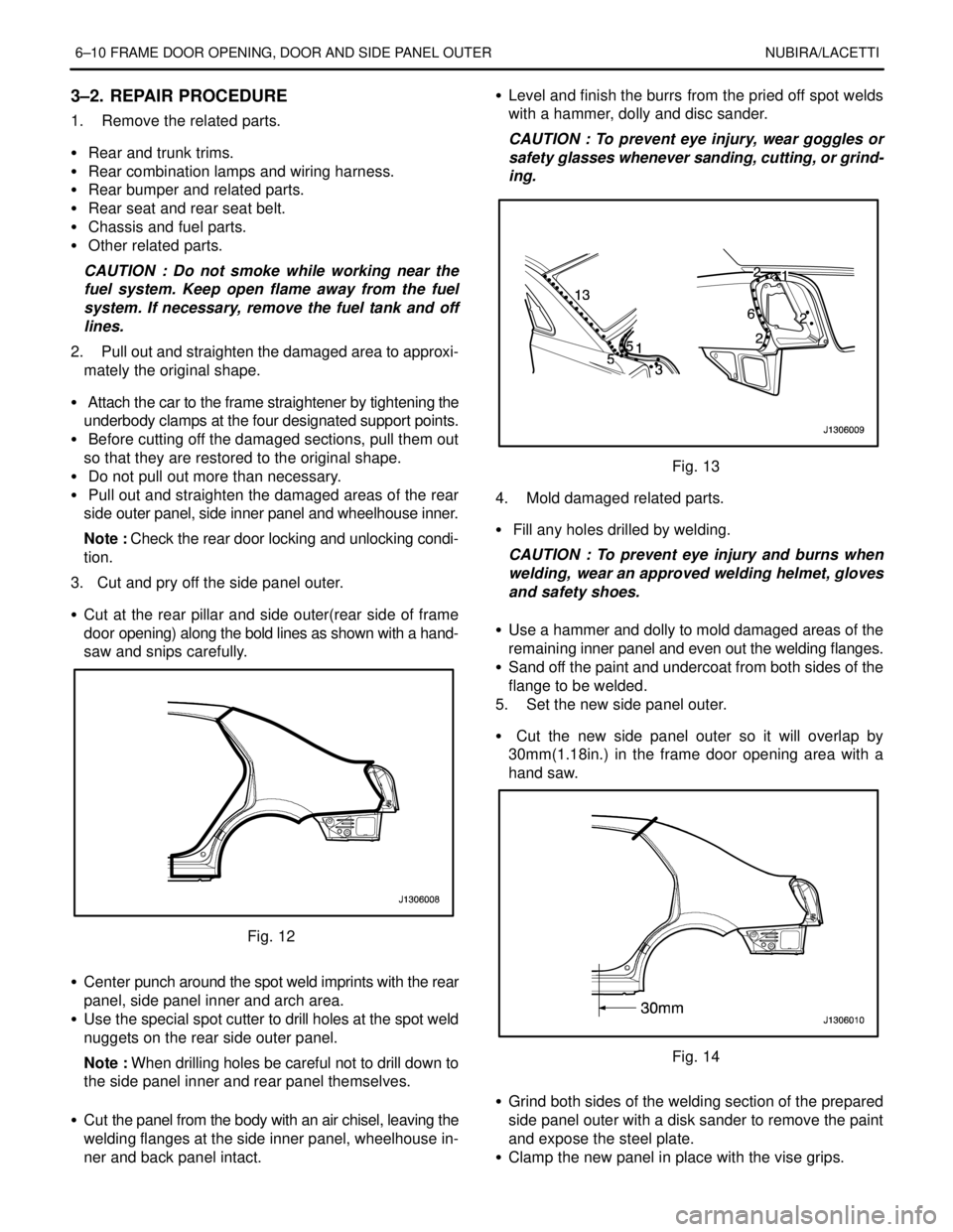
6–10 FRAME DOOR OPENING, DOOR AND SIDE PANEL OUTER NUBIRA/LACETTI
3–2. REPAIR PROCEDURE
1. Remove the related parts.
S Rear and trunk trims.
S Rear combination lamps and wiring harness.
S Rear bumper and related parts.
S Rear seat and rear seat belt.
S Chassis and fuel parts.
S Other related parts.
CAUTION : Do not smoke while working near the
fuel system. Keep open flame away from the fuel
system. If necessary, remove the fuel tank and off
lines.
2. Pull out and straighten the damaged area to approxi-
mately the original shape.
S Attach the car to the frame straightener by tightening the
underbody clamps at the four designated support points.
S Before cutting off the damaged sections, pull them out
so that they are restored to the original shape.
S Do not pull out more than necessary.
S Pull out and straighten the damaged areas of the rear
side outer panel, side inner panel and wheelhouse inner.
Note : Check the rear door locking and unlocking condi-
tion.
3. Cut and pry off the side panel outer.
S Cut at the rear pillar and side outer(rear side of frame
door opening) along the bold lines as shown with a hand-
saw and snips carefully.
Fig. 12
S Center punch around the spot weld imprints with the rear
panel, side panel inner and arch area.
S Use the special spot cutter to drill holes at the spot weld
nuggets on the rear side outer panel.
Note : When drilling holes be careful not to drill down to
the side panel inner and rear panel themselves.
S Cut the panel from the body with an air chisel, leaving the
welding flanges at the side inner panel, wheelhouse in-
ner and back panel intact.S Level and finish the burrs from the pried off spot welds
with a hammer, dolly and disc sander.
CAUTION : To prevent eye injury, wear goggles or
safety glasses whenever sanding, cutting, or grind-
ing.
Fig. 13
4. Mold damaged related parts.
S Fill any holes drilled by welding.
CAUTION : To prevent eye injury and burns when
welding, wear an approved welding helmet, gloves
and safety shoes.
S Use a hammer and dolly to mold damaged areas of the
remaining inner panel and even out the welding flanges.
S Sand off the paint and undercoat from both sides of the
flange to be welded.
5. Set the new side panel outer.
S Cut the new side panel outer so it will overlap by
30mm(1.18in.) in the frame door opening area with a
hand saw.
Fig. 14
S Grind both sides of the welding section of the prepared
side panel outer with a disk sander to remove the paint
and expose the steel plate.
S Clamp the new panel in place with the vise grips.