2004 DAEWOO NUBIRA Functional Check
[x] Cancel search: Functional CheckPage 249 of 2643

ENGINE CONTROLS 1F – 3
DAEWOO V–121 BL4
DTC P0562 System Voltage(Engine Side) Too
Low 1F–270. . . . . . . . . . . . . . . . . . . . . . . . . . . . . . . . . .
DTC P0563 System Voltage(Engine Side) Too
High 1F–272. . . . . . . . . . . . . . . . . . . . . . . . . . . . . . . . . .
DTC P0601 Engine Control Module Checksum
Error 1F–274. . . . . . . . . . . . . . . . . . . . . . . . . . . . . . . . .
DTC P0604 Engine Control Module Internal/External
RAM Error 1F–275. . . . . . . . . . . . . . . . . . . . . . . . . . . .
DTC P0605 Engine Control Module INMVY Write
Error 1F–276. . . . . . . . . . . . . . . . . . . . . . . . . . . . . . . . .
DTC P0656 Fuel Level Gauge Circuit Fault 1F–277. .
DTC P1181 Variable Intake Manifold Solenoid
Low Voltage 1F–279. . . . . . . . . . . . . . . . . . . . . . . . . . .
DTC P1182 Variable Intake Manifold Solenoid
High Voltage 1F–281. . . . . . . . . . . . . . . . . . . . . . . . . .
DTC P1230 Fuel Pump Relay Low Voltage
(1.4L DOHC) 1F–283. . . . . . . . . . . . . . . . . . . . . . . . . .
DTC P1230 Fuel Pump Relay Low Voltage
(1.6L DOHC) 1F–286. . . . . . . . . . . . . . . . . . . . . . . . . .
DTC P1231 Fuel Pump Relay High Voltage
(1.4L DOHC) 1F–289. . . . . . . . . . . . . . . . . . . . . . . . . .
DTC P1231 Fuel Pump Relay High Voltage
(1.6L DOHC) 1F–292. . . . . . . . . . . . . . . . . . . . . . . . . .
DTC P1320 Crankshaft Segment Period
Segment Adaptation At Limit 1F–295. . . . . . . . . . . .
DTC P1321 Crankshaft Segment Period Tooth
Error 1F–297. . . . . . . . . . . . . . . . . . . . . . . . . . . . . . . . .
DTC P1382 Rough Road Data Invalid
(NON ABS) 1F–299. . . . . . . . . . . . . . . . . . . . . . . . . . .
DTC P1382 Rough Road Data Invalid (ABS) 1F–302
DTC P1385 Rough Road Sensor Circuit Fault
(NON ABS) 1F–305. . . . . . . . . . . . . . . . . . . . . . . . . . .
DTC P1402 Exhaust Gas Recirculation
Blocked 1F–308. . . . . . . . . . . . . . . . . . . . . . . . . . . . . . .
DTC P1403 Exhaust Gas Recirculation Valve
Failure 1F–310. . . . . . . . . . . . . . . . . . . . . . . . . . . . . . . .
DTC P1404 Exhaust Gas Recirculation Closed1F–313
DTC P1511 Idle Charge Actuator Circuit Fault 1F–316
DTC P1512 Idle Charge Actuator Mechanical
Error 1F–319. . . . . . . . . . . . . . . . . . . . . . . . . . . . . . . . .
DTC P1513 Idle Charge Actuator Functional
Error 1F–321. . . . . . . . . . . . . . . . . . . . . . . . . . . . . . . . .
DTC P1537 A/C Compressor Relay High
Voltage 1F–324. . . . . . . . . . . . . . . . . . . . . . . . . . . . . . .
DTC P1538 A/C Compressor Relay Low
Voltage 1F–326. . . . . . . . . . . . . . . . . . . . . . . . . . . . . . .
DTC P1610 Main Relay High Voltage
(1.4L DOCH) 1F–328. . . . . . . . . . . . . . . . . . . . . . . . . .
DTC P1610 Main Relay High Voltage
(1.6L DOHC) 1F–330. . . . . . . . . . . . . . . . . . . . . . . . . .
DTC P1611 Main Relay Low Voltage
(1.4L DOHC) 1F–332. . . . . . . . . . . . . . . . . . . . . . . . . . DTC P1611 Main Relay Low Voltage
(1.6L DOHC) 1F–334. . . . . . . . . . . . . . . . . . . . . . . . . .
DTC P1628 Immobilizer No Successful
Communication 1F–336. . . . . . . . . . . . . . . . . . . . . . . .
DTC P1629 Immobilizer Wrong Computation 1F–338
DTC P1660 Malfunction Indicator Lamp (MIL)
High Voltage 1F–340. . . . . . . . . . . . . . . . . . . . . . . . . .
DTC P1661 Malfunction Indicator Lamp (MIL)
Low Voltage 1F–342. . . . . . . . . . . . . . . . . . . . . . . . . . .
TROUBLE CODE DIAGNOSIS (1.8L DOHC) 1F–344.
Clearing Trouble Codes 1F–344. . . . . . . . . . . . . . . . . . .
Diagnostic Trouble Codes (1.8L DOHC) 1F–344. . . .
DTC P0106 Manifold Absolute Pressure
Rationality 1F–347. . . . . . . . . . . . . . . . . . . . . . . . . . . .
DTC P0107 Manifold Absolut Pressure Low
Voltage 1F–349. . . . . . . . . . . . . . . . . . . . . . . . . . . . . . .
DTC P0108 Manifold Absolut Pressure High
Voltage 1F–352. . . . . . . . . . . . . . . . . . . . . . . . . . . . . . .
DTC P0112 Intake Air Temperature Low
Voltage 1F–355. . . . . . . . . . . . . . . . . . . . . . . . . . . . . . .
DTC P0113 Intake Air Temperature High
Voltage 1F–358. . . . . . . . . . . . . . . . . . . . . . . . . . . . . . .
DTC P0117 Engine Coolant Temperature Low
Voltage 1F–361. . . . . . . . . . . . . . . . . . . . . . . . . . . . . . .
DTC P0118 Engine Coolant Temperature High
Voltage 1F–363. . . . . . . . . . . . . . . . . . . . . . . . . . . . . . .
DTC P0122 Throttle Position Sensor Low
Voltage 1F–366. . . . . . . . . . . . . . . . . . . . . . . . . . . . . . .
DTC P0123 Throttle Position Sensor High
Voltage 1F–369. . . . . . . . . . . . . . . . . . . . . . . . . . . . . . .
DTC P0131 Front Heated Oxygen Sensor
(HO2S1) Low Voltage 1F–372. . . . . . . . . . . . . . . . . .
DTC P0132 Front Heated Oxygen Sensor
(HO2S1) High Voltage 1F–375. . . . . . . . . . . . . . . . . .
DTC P0133 Front Heated Oxygen Sensor
(HO2S1) Slow Response 1F–378. . . . . . . . . . . . . . .
DTC P0134 Front Heated Oxygen Sensor
(HO2S1) No Activity or Open 1F–382. . . . . . . . . . . .
DTC P0135 Front Heated Oxygen Sensor
(HO2S1) Heater Circuit Not Functioning 1F–385. . .
DTC P0137 Rear Heated Oxygen Sensor
(HO2S2) Low Voltage 1F–388. . . . . . . . . . . . . . . . . .
DTC P0138 Rear Heated Oxygen Sensor
(HO2S2) High Voltage 1F–391. . . . . . . . . . . . . . . . . .
DTC P0140 Rear Heated Oxygen Sensor
(HO2S2) No Activity or Open 1F–394. . . . . . . . . . . .
DTC P0141 Rear Heated Oxygen Sensor
(HO2S2) Heater Circuit Not Functioning 1F–397. . .
DTC P0171 Fuel Trim System Too Lean 1F–400. . . .
DTC P0172 Fuel Trim System Too Rich 1F–404. . . . .
DTC P0201 Injector 1 Circuit Fault 1F–408. . . . . . . . .
DTC P0202 Injector 2 Circuit Fault 1F–411. . . . . . . . .
Page 567 of 2643

ENGINE CONTROLS 1F – 321
DAEWOO V–121 BL4
DIAGNOSTIC TROUBLE CODE (DTC) P1513
IDLE CHARGE ACTUATOR FUNCTIONAL ERROR
Circuit Description
The aim of the MTIA (Main Throttle Idle Actuator) is to con-
trol the idle speed with the throttle body itself. The throttle
is motorized for low opening angle (0°, 19°). The charac-
teristics of the air flow are not the same for low and high
opening angles. As a matter of fact, the gradient of the
mass air flow function of TPS is lower for small angles that
permits to be more precise during the idle speed control.
Out of idle speed the throttle is actuated mechanically by
a classical accelcable.
The DC–motor commands the actuator for idle
Conditions for Setting the DTC
S Mechanical problems exists.
– problem of accel cable hose
– problem inside MTIA : seizing by friction,
snooted, fouling.
S Absolute adaptation or relative is not correct after
16 attemps.
Action Taken When the DTC Sets
S The Malfunction Indicator Lamp (MIL) will not illumi-
nate.S The ECM will store conditions which were present
when the DTC was set as Failure Records data
only.
S This information will not be stored in the Freeze
Frame data.
Conditions for Clearing the MIL/DTC
S A history DTC will clear after 40 consecutive warm–
up cycles without a fault.
S DTC(s) can be cleared by using the scan tool.
S Disconnecting the ECM battery feed for more than
10 seconds.
Diagnostic Aids
An Intermittent problem may be caused by a poor connec-
tion, rubbed through wire insulation, or wire that is broken
inside the insulation.
Any circuitry, that is suspected as causing the complaint,
should be thoroughly checked for the following conditions.
S Backed–out terminals
S Improper mating
S Broken locks
S Improperly formed
S Damaged terminals
S Poor terminal to wire connection
S Physical damage to the wiring harness
Page 568 of 2643

1F – 322IENGINE CONTROLS
DAEWOO V–121 BL4
DTC P1513 – Idle Charge Actuator Functional Error
StepActionValue(s)YesNo
1Perform an On–Board Diagnostic (EOBD) System
Check.
Is the system check complete?–Go to Step 2Go to
”On–Board
Diagnostic Sys-
tem Check”
2Turn the Turn the ignition switch to ON.
Is the Malfunction Indicator Lamp(MIL) on steady?–Go to Step 4Go to Step 3
31. Connect the scan tool the DLC.
2. Turn the Turn the ignition switch to ON.
Does the scan tool display serial data?–Go to Step 4Try with
another scan
tool
4Start the engine.
Does the engine start?–Go to Step 5Go to
”Engine Cranks
But Will Not
Run”
51. Turn the ignition switch to LOCK.
2. Connect the scan tool to the DLC.
Turn the Turn the ignition switch to ON.
Are any Diagnostic Trouble Codes (DTCs) dis-
played?–Go to Step 6Try with
another scan
tool
6Refer to the applicable DTC table.
Is only one DTC identified as valid trouble code
P1513?–Go to Step 7Go to Applica-
ble DTC Table
and Go to
”Multiple DTC”
71. Turn the ignition switch to LOCK.
2. Disconnect the MTIA connector.
3. Disconnect the ECM connector.
4. Measure resistance between MTIA connector
terminal 4 and ECM connector terminal 43.
Does the resistance measure with the value speci-
fied?0WGo to Step 8Go to Step 9
8Measure resistance between MTIA connector termi-
nal 8 and ECM connector terminal 19.
Does the resistance measure within the value speci-
fied?0WGo to Step 10Go to Step 11
91. Repair the wire or the connector terminal as
needed.
2. Clear any DTCs from ECM.
3. Perform the diagnostic system check.
Is the repair complete?–System OKGo to Step 8
101. Repair the wire or the connector terminal as
needed.
2. Clear any DTCs from ECM.
3. Perform the diagnostic system check.
Is the repair complete?–System OKGo to Step 11
111. Turn the ignition switch to LOCK.
2. Replace the throttle body assembly.
S Clear any DTCs from ECM.
S Perform the diagnostic system check.
Is the repair complete?–System OKGo to Step 12
Page 876 of 2643

1F – 630IENGINE CONTROLS
DAEWOO V–121 BL4
COMPREHENSIVE COMPONENT
MONITOR DIAGNOSTIC OPERATION
Comprehensive component monitoring diagnostics are
required to monitor emissions–related input and output
powertrain components.
Input Components
Input components are monitored for circuit continuity and
out–of–range values. This includes rationality checking.
Rationality checking refers to indicating a fault when the
signal from a sensor does not seem reasonable, i.e.
Throttle Position (TP) sensor that indicates high throttle
position at low engine loads or Manifold Absolute Pressure
(MAP) voltage. Input components may include, but are not
limited to, the following sensors:
S Vehicle Speed Sensor (VSS).
S Crankshaft Position (CKP) sensor.
S Throttle Position (TP) sensor.
S Engine Coolant Temperature (ECT) sensor.
S Camshaft Position (CMP) sensor.
S Manifold Absolute Pressure (MAP) sensor.
In addition to the circuit continuity and rationality check,
the ECT sensor is monitored for its ability to achieve a
steady state temperature to enable closed loop fuel con-
trol.
Output Components
Output components are diagnosed for proper response to
control module commands. Components where functional
monitoring is not feasible will be monitored for circuit conti-
nuity and out–of–range values if applicable. Output com-
ponents to be monitored include, but are not limited to the
following circuit:
S Idle Air Control (IAC) Motor.
S Control module controlled EVAP Canister Purge
Valve.
S A/C relays.
S Cooling fan relay.
S VSS output.
S MIL control.
Refer to ”Engine Control Module” and Sensors in this sec-
tion.
Passive and Active Diagnostic Tests
A passive test is a diagnostic test which simply monitors
a vehicle system or component. Conversely, an active
test, actually takes some sort of action when performing
diagnostic functions, often in response to a failed passive
test. For example, the Exhaust Gas Recirculation (EGR)
diagnostic active test will force the EGR valve open during
closed throttle deceleration and/or force the EGR valve
closed during a steady state. Either action should result in
a change in manifold pressure.
Intrusive Diagnostic Tests
This is any on–board test run by the Diagnostic Manage-
ment System which may have an effect on vehicle perfor-
mance or emission levels.
Warm–Up Cycle
A warm–up cycle means that engine temperature must
reach aminimum of 160°F (70°C) and rise at least 72°F
(22°C) over the course of a trip.
Freeze Frame
Freeze Frame is an element of the Diagnostic Manage-
ment System which stores various vehicle information at
the moment an emissions–related fault is stored in
memory and when the Malfunction Indicator Lamp (MIL)
is commanded on. These data can help to identify the
cause of a fault.
Failure Records
Failure Records data is an enhancement of the EOBD
Freeze Frame feature. Failure Records store the same ve-
hicle information as does Freeze Frame, but it will store
that information for any fault which is stored in onboard
memory, while Freeze Frame stores information only for
emission–related faults that command the MIL on.
COMMON EOBD TERMS
Diagnostic
When used as a noun, the word diagnostic refers to any
on–board test run by the vehicle’s Diagnostic Manage-
ment System. A diagnostic is simply a test run on a system
or component to determine if the system or component is
operating according to specification. There are many diag-
nostics, shown in the following list:
S Misfire
S Front Heated Oxygen Sensor (HO2S1)
S Rear Heated Oxygen Sensor (HO2S2)
S Exhaust Gas Recirculation (EGR)
S Catalyst monitoring
Enable Criteria
The term ”enable criteria” is engineering language for the
conditions necessary for a given diagnostic test to run.
Each diagnostic has a specific list of conditions which
must be met before the diagnostic will run.
”Enable criteria” is another way of saying ”conditions re-
quired.”
The enable criteria for each diagnostic is listed on the first
page of the Diagnostic Trouble Code (DTC) description
under the heading ”Conditions for Setting the DTC.” En-
able criteria varies with each diagnostic and typically in-
cludes, but is not limited to, the following items:
S Engine speed.
S Vehicle speed
S Engine Coolant Temperature (ECT)
S Manifold Absolute Pressure (MAP)
Page 877 of 2643

ENGINE CONTROLS 1F – 631
DAEWOO V–121 BL4
S Barometric Pressure (BARO)
S Intake Air Temperature (IAT)
S Throttle Position (TP)
S High canister purge
S Fuel trim
S A/C on
Trip
Technically, a trip is a key–on run key–off cycle in which all
the enable criteria for a given diagnostic are met, allowing
the diagnostic to run. Unfortunately, this concept is not
quite that simple. A trip is official when all the enable crite-
ria for a given diagnostic are met. But because the enable
criteria vary from one diagnostic to another, the definition
of trip varies as well. Some diagnostics are run when the
vehicle is at operating temperature, some when the ve-
hicle first starts up; some require that the vehicle be cruis-
ing at a steady highway speed, some run only when the
vehicle is at idle; some diagnostics function with the
Torque Converter Clutch (TCC) disabled. Some run only
immediately following a cold engine startup.
A trip then, is defined as a key–on run key–off cycle in
which the vehicle was operated in such a way as to satisfy
the enables criteria for a given diagnostic, and this diag-
nostic will consider this cycle to be one trip. However,
another diagnostic with a different set of enable criteria
(which were not met) during this driving event, would not
consider it a trip. No trip will occur for that particular diag-
nostic until the vehicle is driven in such a way as to meet
all the enable criteria
Diagnostic Information
The diagnostic charts and functional checks are designed
to locate a faulty circuit or component through a process
of logical decisions. The charts are prepared with the re-
quirement that the vehicle functioned correctly at the time
of assembly and that there are not multiple faults present.
There is a continuous self–diagnosis on certain control
functions. This diagnostic capability is complimented by
the diagnostic procedures contained in this manual. The
language of communicating the source of the malfunction
is a system of diagnostic trouble codes. When a malfunc-
tion is detected by the control module, a diagnostic trouble
code is set and the Malfunction Indicator Lamp (MIL) is illu-
minated.
Malfunction Indicator Lamp (MIL)
The Malfunction Indicator Lamp (MIL) is required by On–
Board Diagnostics (EOBD) that it illuminates under a strict
set of guide lines.
Basically, the MIL is turned on when the engine control
module (ECM) detects a DTC that will impact the vehicle
emissions.The MIL is under the control of the Diagnostic Executive.
The MIL will be turned on if an emissions–related diagnos-
tic test indicates a malfunction has occurred. It will stay on
until the system or component passes the same test, for
three consecutive trips, with no emissions related faults.
Extinguishing the MIL
When the MIL is on, the Diagnostic Executive will turn off
the MIL after three consecutive trips that a ”test passed”
has been reported for the diagnostic test that originally
caused the MIL to illuminate. Although the MIL has been
turned off, the DTC will remain in the ECM memory (both
Freeze Frame and Failure Records) until forty (40) warm–
up cycles after no faults have been completed.
If the MIL was set by either a fuel trim or misfire–related
DTC, additional requirements must be met. In addition to
the requirements stated in the previous paragraph, these
requirements are as follows:
S The diagnostic tests that are passed must occur
with 375 rpm of the rpm data stored at the time the
last test failed.
S Plus or minus ten percent of the engine load that
was stored at the time the last test failed. Similar
engine temperature conditions (warmed up or
warming up) as those stored at the time the last
test failed.
Meeting these requirements ensures that the fault which
turned on the MIL has been corrected.
The MIL is on the instrument panel and has the following
functions:
S It informs the driver that a fault that affects vehicle
emission levels has occurred and that the vehicle
should be taken for service as soon as possible.
S As a system check, the MIL will come on with the
key ON and the engine not running. When the en-
gine is started, the MIL will turn OFF.
S When the MIL remains ON while the engine is run-
ning, or when a malfunction is suspected due to a
driveability or emissions problem, an EOBD System
Check must be performed. The procedures for
these checks are given in EOBD System Check.
These checks will expose faults which may not be
detected if other diagnostics are performed first.
Data Link Connector (DLC)
The provision for communicating with the control module
is the Data Link Connector (DLC). The DLC is used to con-
nect to a scan tool. Some common uses of the scan tool
are listed below:
S Identifying stored DTCs.
S Clearing DTCs.
S Performing output control tests.
S Reading serial data.
Page 1043 of 2643

SECTION : 4C
POWER BOOSTER
TABLE OF CONTENTS
SPECIFICATIONS4C–1 . . . . . . . . . . . . . . . . . . . . . . . . . .
Fasrener Tightening Specifications 4C–1. . . . . . . . . .
DIAGNOSIS4C–1 . . . . . . . . . . . . . . . . . . . . . . . . . . . . . . . .
Power Booster Functional Check 4C–1. . . . . . . . . . . .
MAINTENANCE AND REPAIR4C–2 . . . . . . . . . . . . . . . ON–VEHICLE SERVICE 4C–2. . . . . . . . . . . . . . . . . . . . .
Vacuum Hose 4C–2. . . . . . . . . . . . . . . . . . . . . . . . . . . .
Power Booster Assembly 4C–2. . . . . . . . . . . . . . . . . . .
GENERAL DESCRIPTION AND SYSTEM
OPERATION4C–6 . . . . . . . . . . . . . . . . . . . . . . . . . . . . . .
Power Booster 4C–6. . . . . . . . . . . . . . . . . . . . . . . . . . . .
SPECIFICATIONS
FASRENER TIGHTENING SPECIFICATIONS
ApplicationNSmLb–FtLb–In
Booster–to–Bracket Nuts (Right–Hand Drive)2216–
Booster–to–Dash Panel Nut (Left–Hand
Drive)2216–
Booster Hex Nut and Pushrod Clevis1813–
Brake Line Fittings1612–
DIAGNOSIS
POWER BOOSTER FUNCTIONAL
CHECK
1. With the engine stopped, eliminate vacuum in the
booster by pumping the brake pedal several times.
2. Push the pedal down and hold in this position.
3. Start the engine.4. The booster is OK if the pedal drops further be-
cause of extra force produced.
If the brake pedal does not drop, the vacuum system (vac-
uum hoses, check valve, etc.) is probably defective and
should be checked.
If no defect is revealed by checking the vacuum system,
the defect is in the booster itself.
Page 1044 of 2643
4C – 2IPOWER BOOSTER
DAEWOO V–121 BL4
MAINTENANCE AND REPAIR
ON–VEHICLE SERVICE
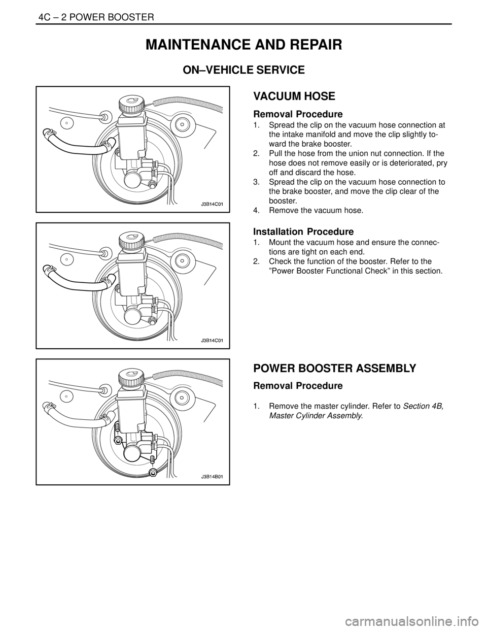
VACUUM HOSE
Removal Procedure
1. Spread the clip on the vacuum hose connection at
the intake manifold and move the clip slightly to-
ward the brake booster.
2. Pull the hose from the union nut connection. If the
hose does not remove easily or is deteriorated, pry
off and discard the hose.
3. Spread the clip on the vacuum hose connection to
the brake booster, and move the clip clear of the
booster.
4. Remove the vacuum hose.
Installation Procedure
1. Mount the vacuum hose and ensure the connec-
tions are tight on each end.
2. Check the function of the booster. Refer to the
”Power Booster Functional Check” in this section.
POWER BOOSTER ASSEMBLY
Removal Procedure
1. Remove the master cylinder. Refer to Section 4B,
Master Cylinder Assembly.
Page 1350 of 2643

SECTION : 5A1
ZF 4 HP 16 AUTOMATIC TRANSAXLE
CAUTION : Disconnect the negative battery cable before removing or installing any electrical unit or when a tool
or equipment could easily come in contact with exposed electrical terminals. Disconnecting this cable will help
prevent personal injury and damage to the vehicle. The ignition must also be in LOCK unless otherwise noted.
TABLE OF CONTENTS
INTRODUCTION5A1–3 . . . . . . . . . . . . . . . . . . . . . . . . . . .
ZF 4HP 16 Automatic Transaxle 5A1–3. . . . . . . . . . . .
Transaxle Components 5A1–4. . . . . . . . . . . . . . . . . . . .
SPECIFICATIONS5A1–5 . . . . . . . . . . . . . . . . . . . . . . . . .
General Specifications 5A1–5. . . . . . . . . . . . . . . . . . . .
Transaxle Gear Ratio 5A1–5. . . . . . . . . . . . . . . . . . . . . .
Fluid Capacity 5A1–5. . . . . . . . . . . . . . . . . . . . . . . . . . . .
Fastener Tightening Specifications 5A1–5. . . . . . . . . .
Shift Speed Chart 5A1–7. . . . . . . . . . . . . . . . . . . . . . . . .
Line Pressure 5A1–8. . . . . . . . . . . . . . . . . . . . . . . . . . . .
SPECIAL TOOLS5A1–9 . . . . . . . . . . . . . . . . . . . . . . . . . .
Special Tools Table 5A1–9. . . . . . . . . . . . . . . . . . . . . . .
SCHEMATIC AND ROUTING DIAGRAMS5A1–11 . . .
Transaxle Control Module (1 of 2) 5A1–11. . . . . . . . . .
Transaxle Control Module (2 of 2) 5A1–12. . . . . . . . . .
Shift Mode Diagram 5A1–13. . . . . . . . . . . . . . . . . . . . . .
Power Flow Diagram 5A1–17. . . . . . . . . . . . . . . . . . . . .
COMPONENT LOCATOR5A1–33 . . . . . . . . . . . . . . . . . .
Transaxle Identification Information 5A1–33. . . . . . . .
Torque Converter 5A1–34. . . . . . . . . . . . . . . . . . . . . . . .
Transaxle Housing 5A1–35. . . . . . . . . . . . . . . . . . . . . . .
Oil Pump 5A1–36. . . . . . . . . . . . . . . . . . . . . . . . . . . . . . .
Rear Cover & Oil Pan Cover 5A1–37. . . . . . . . . . . . . .
Parking Lever 5A1–38. . . . . . . . . . . . . . . . . . . . . . . . . . .
Input Shaft & Shift Gear 5A1–39. . . . . . . . . . . . . . . . . .
Valve Body 5A1–41. . . . . . . . . . . . . . . . . . . . . . . . . . . . .
Gear Shift Control 5A1–42. . . . . . . . . . . . . . . . . . . . . . .
DIAGNOSTIC INFORMATION AND PROCEDURES
DIAGNOSIS5A1–43 . . . . . . . . . . . . . . . . . . . . . . . . . . . .
Basic Knowledge Required 5A1–43. . . . . . . . . . . . . . . .
Functional Check Procedure 5A1–43. . . . . . . . . . . . . .
Line Pressure Check Procedure 5A1–43. . . . . . . . . . .
Clutch Plate Diagnosis 5A1–45. . . . . . . . . . . . . . . . . . .
Cooler Flushing and Flow Test 5A1–45. . . . . . . . . . . . . Transaxle Fluid Level Service Procedure 5A1–45. . . .
Electrical/Garage Shift Test 5A1–47. . . . . . . . . . . . . . .
Road Test Procedure 5A1–47. . . . . . . . . . . . . . . . . . . . .
Torque Converter Lock–Up Clutch(TCC)
Diagnosis 5A1–48. . . . . . . . . . . . . . . . . . . . . . . . . . . . .
TCM Initialization Procedure 5A1–50. . . . . . . . . . . . . .
Shift Speed Chart 5A1–51. . . . . . . . . . . . . . . . . . . . . . . .
Internal Wiring Harness Check 5A1–51. . . . . . . . . . . .
Transaxle Wiring Harness Connector 5A1–54. . . . . . .
Symptom Diagnosis 5A1–56. . . . . . . . . . . . . . . . . . . . . .
DIAGNOSTIC TROUBLE CODE DIAGNOSIS5A1–60
Diagnostic Trouble Code (DTC) Identification 5A1–60
DTC P0562 – System Voltage Low 5A1–68. . . . . . . . .
DTC P0563 – System Voltage High 5A1–71. . . . . . . .
DTC P0601 – Internal Control Module Memory
Checksum Error 5A1–74. . . . . . . . . . . . . . . . . . . . . . .
DTC P0603 – Internal Control Module Keep
Alive Memory(KAM) Error 5A1–76. . . . . . . . . . . . . . .
DTC P0604 – Internal Control Module Random
Access Memory(RAM) Error 5A1–78. . . . . . . . . . . . .
DTC P0606 – Transaxle Control Module
Processor Fault 5A1–80. . . . . . . . . . . . . . . . . . . . . . . .
DTC P0703 – Brake Switch Circuit
Malfunction 5A1–83. . . . . . . . . . . . . . . . . . . . . . . . . . .
DTC P0705 – Transmission Range Sensor
Circuit Malfunction(PRNDL Input) 5A1–86. . . . . . . .
DTC P0710 – Transmission Fluid Temperature
Sensor Circuit Malfunction 5A1–89. . . . . . . . . . . . . .
DTC P0715 – Input Speed Sensor(ISS) Circuit
Malfunction 5A1–92. . . . . . . . . . . . . . . . . . . . . . . . . . .
DTC P0716 – Input Speed Sensor(ISS) Circuit
Range/Performance 5A1–95. . . . . . . . . . . . . . . . . . . .
DTC P0717 – Input Speed Sensor(ISS) Circuit
No Signal 5A1–98. . . . . . . . . . . . . . . . . . . . . . . . . . . . .
DTC P0720 – Output Speed Sensor(OSS)
Circuit Malfunction 5A1–101. . . . . . . . . . . . . . . . . . . .
DTC P0721 – Output Speed Sensor(OSS)
Circuit Range/Performance 5A1–104. . . . . . . . . . . . .