2004 DAEWOO NUBIRA INTERIOR TRIM
[x] Cancel search: INTERIOR TRIMPage 5 of 2643

v
TABLE OF CONTENTS
Section 0B General Information
Section 1 Engine
Section 1A General Engine Information
Section 1C1 1.4L/1.6L DOHC Engine Mechanical
Section 1C2 1.8L DOHC Engine Mechanical
Section 1D Engine Cooling
Section 1E Engine Electrical
Section 1F Engine Controls
Section 1G Engine Exhaust
Section 2 Suspension
Section 2A Suspension Diagnosis
Section 2B Wheel Alignment
Section 2C Front Suspension
Section 2D Rear Suspension
Section 2E Tires and Wheels
Section 3 Driveline/Axle
Section 3A Automatic Transaxle Drive Axle
Section 3B Manual Transaxle Drive Axle
Section 4 Brakes
Section 4A Hydraulic Brakes
Section 4B Master Cylinder
Section 4C Power Booster
Section 4D Front Disc Brakes
Section 4E1 Rear Disc Brakes
Section 4E2 Rear Drum Brakes
Section 4F Antilock Brake System
Section 4G Parking Brake
Section 5 Transmission/Transaxle
Section 5A1 ZF 4HP16 Automatic Transaxle
Section 5A2 AISIN Automatic Transaxle
Section 5B Five-Speed Manual Transaxle
Section 5C Clutch
Section 6 Steering
Section 6A Power Steering System
Section 6B Power Steering PumpSection 6C Power Steering Gear
Section 6E Steering Wheel and Column
Section 7 Heating, Ventilation, and Air
Conditioning (HVAC)
Section 7A Heating and Ventilation System
Section 7B Manual Control Heating, Ventilation,
and Air Conditioning System
Section 7D Automatic Temperature Control HVAC
Section 8 Restraints
Section 8A Seat Belts
Section 8B Supplemental Inflatable Restraints
(SIR)
Section 9 Body and Accessories
Section 9A Body Wiring System
Section 9B Lighting Systems
Section 9C Horns
Section 9D Wipers/Washer Systems
Section 9E Instrumentation/Driver Information
Section 9F Audio Systems
Section 9G Interior Trim
Section 9H Seats
Section 9I Waterleaks
Section 9J Windnoise
Section 9K Squeaks and Rattles
Section 9L Glass and Mirrors
Section 9M Exterior Trim
Section 9N Frame and Underbody
Section 9O Bumpers and Fascias
Section 9P Doors
Section 9Q Roof
Section 9R Body Front End
Section 9S Body Rear End
Section 9T1 Remote Keyless Entry and Anti–Theft
System
Section 9T2 Immobilizer Anti–Theft System
Page 867 of 2643
ENGINE CONTROLS 1F – 621
DAEWOO V–121 BL4
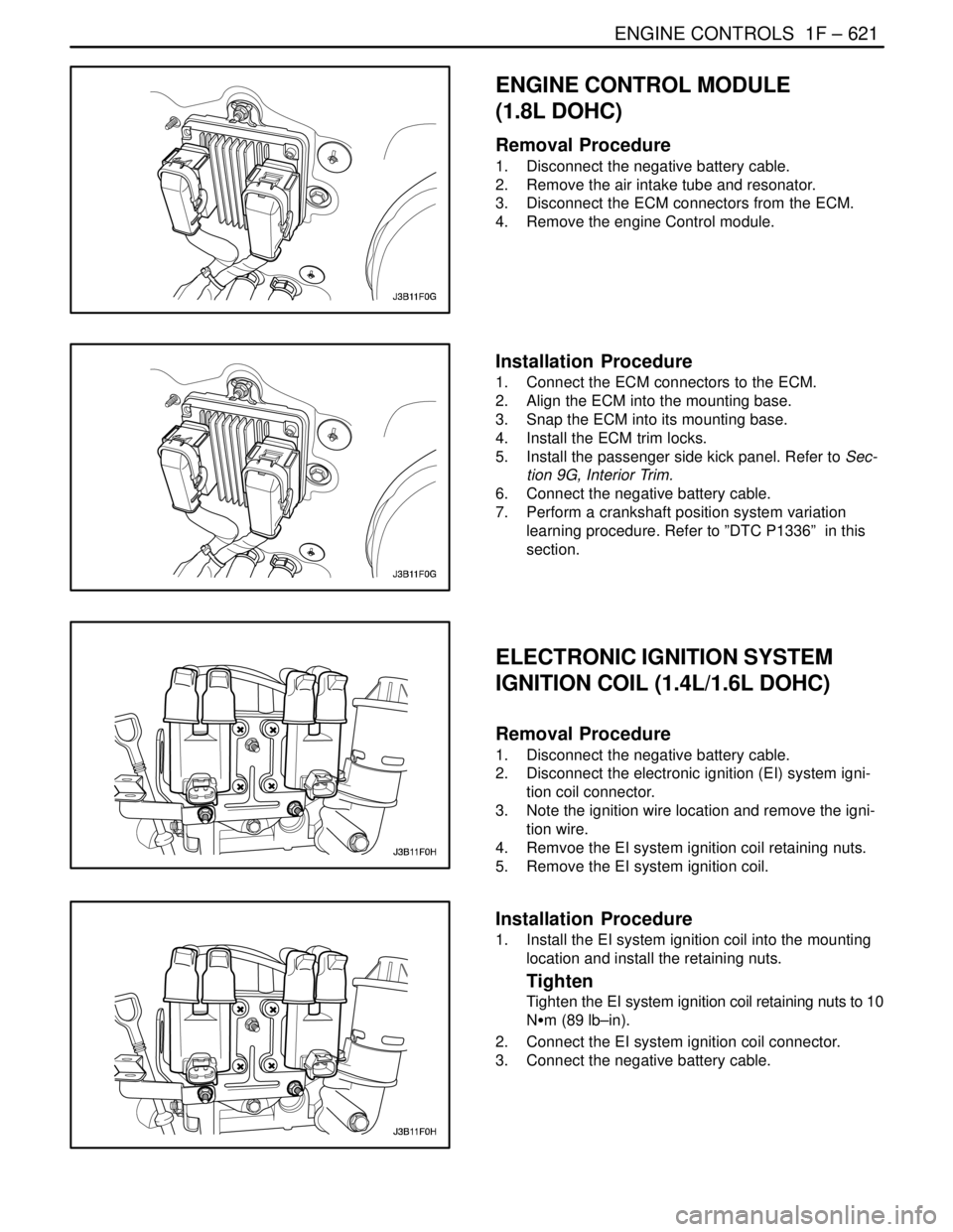
ENGINE CONTROL MODULE
(1.8L DOHC)
Removal Procedure
1. Disconnect the negative battery cable.
2. Remove the air intake tube and resonator.
3. Disconnect the ECM connectors from the ECM.
4. Remove the engine Control module.
Installation Procedure
1. Connect the ECM connectors to the ECM.
2. Align the ECM into the mounting base.
3. Snap the ECM into its mounting base.
4. Install the ECM trim locks.
5. Install the passenger side kick panel. Refer to Sec-
tion 9G, Interior Trim.
6. Connect the negative battery cable.
7. Perform a crankshaft position system variation
learning procedure. Refer to ”DTC P1336” in this
section.
ELECTRONIC IGNITION SYSTEM
IGNITION COIL (1.4L/1.6L DOHC)
Removal Procedure
1. Disconnect the negative battery cable.
2. Disconnect the electronic ignition (EI) system igni-
tion coil connector.
3. Note the ignition wire location and remove the igni-
tion wire.
4. Remvoe the EI system ignition coil retaining nuts.
5. Remove the EI system ignition coil.
Installation Procedure
1. Install the EI system ignition coil into the mounting
location and install the retaining nuts.
Tighten
Tighten the EI system ignition coil retaining nuts to 10
NSm (89 lb–in).
2. Connect the EI system ignition coil connector.
3. Connect the negative battery cable.
Page 948 of 2643

2D – 6IREAR SUSPENSION
DAEWOO V–121 BL4
MAINTENANCE AND REPAIR
ON–VEHICLE SERVICE
STRUT ASSEMBLY
Removal Procedure
1. Remove the trunk carpeting that covers the rear
strut mounting nuts. For station wagons, remove
the panels that cover the luggage compartment
wheelhouse trim panel (wagon). Refer to Section
9G, Interior Trim.
2. Remove the rear strut mounting nuts.
3. Raise and suitably support the vehicle.
4. Remove the wheel. Refer to Section 2E, Tires and
Wheels.
5. Disconnect the parking brake. Refer to Section 4G,
Parking Brake.
Important : On vehicles equipped with rear drum brakes,
the brake hose will easily disconnect from the strut assem-
bly as the assembly is being removed from the vehicle. On
vehicles equipped with rear disc brakes, the brake hose
can be disconnected from the strut assembly at any time.
6. Remove the clip that holds the brake hose to the
strut assembly.
Page 951 of 2643

REAR SUSPENSION 2D – 9
DAEWOO V–121 BL4
9. Install the trunk carpeting over the rear strut mount-
ing nuts. For station wagons, remove the panels
that cover the luggage compartment wheelhouse
trim panel (wagon). Refer to Section 9G, Interior
Trim.
KNUCKLE ASSEMBLY
Removal Procedure
1. Raise and suitably support the vehicle.
2. Remove the wheel. Refer to Section 2E, Tires and
Wheels.
3. On vehicles equipped with the antilock braking sys-
tem, remove the ABS speed sensor. Refer to Sec-
tion 4F, Antilock Brake System.
4. On vehicles equipped with rear disc brakes, remove
the rear brake caliper from the knuckle assembly.
Refer to Section 4E1, Rear Disc Brakes.
5. Disconnect the parking brake from the knuckle as-
sembly. Refer to Section 4G, Parking Brake.
6. Disconnect the front parallel link from the knuckle.
Refer to ”Front Parallel Link” in this section.
7. Disconnect the rear parallel link from the knuckle.
Refer to ”Rear Parallel Link” in this section.
8. Disconnect the rear trailing link from the rear
knuckle. Refer to ”Rear Trailing Link” in this sec-
tion.
9. On vehicles equipped with rear drum brakes, re-
move the clip that secures the brake line to the
strut assembly.
10. On vehicles equipped with rear drum brakes, dis-
connect the brake line from the knuckle assembly.
Refer to Section 4E2, Rear Drum Brakes.
11. Remove the rear knuckle–to–strut assembly nuts
and the bolts.
12. Disconnect the brake line from the strut assembly
and remove the rear knuckle from the strut assem-
bly.
Page 1154 of 2643
4G – 2IPARKING BRAKE
DAEWOO V–121 BL4
MAINTENANCE AND REPAIR
ON–VEHICLE SERVICE
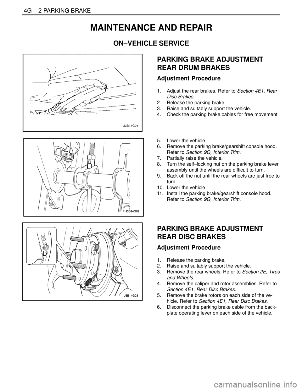
PARKING BRAKE ADJUSTMENT
REAR DRUM BRAKES
Adjustment Procedure
1. Adjust the rear brakes. Refer to Section 4E1, Rear
Disc Brakes.
2. Release the parking brake.
3. Raise and suitably support the vehicle.
4. Check the parking brake cables for free movement.
5. Lower the vehicle
6. Remove the parking brake/gearshift console hood.
Refer to Section 9G, Interior Trim.
7. Partially raise the vehicle.
8. Turn the self–locking nut on the parking brake lever
assembly until the wheels are difficult to turn.
9. Back off the nut until the rear wheels are just free to
turn.
10. Lower the vehicle
11. Install the parking brake/gearshift console hood.
Refer to Section 9G, Interior Trim.
PARKING BRAKE ADJUSTMENT
REAR DISC BRAKES
Adjustment Procedure
1. Release the parking brake.
2. Raise and suitably support the vehicle.
3. Remove the rear wheels. Refer to Section 2E, Tires
and Wheels.
4. Remove the caliper and rotor assemblies. Refer to
Section 4E1, Rear Disc Brakes.
5. Remove the brake rotors on each side of the ve-
hicle. Refer to Section 4E1, Rear Disc Brakes.
6. Disconnect the parking brake cable from the back-
plate operating lever on each side of the vehicle.
Page 1155 of 2643
PARKING BRAKE 4G – 3
DAEWOO V–121 BL4
7. Inspect and replace any parts of doubtful strength
or quality. This can be shown by discoloration from
heat or stress.
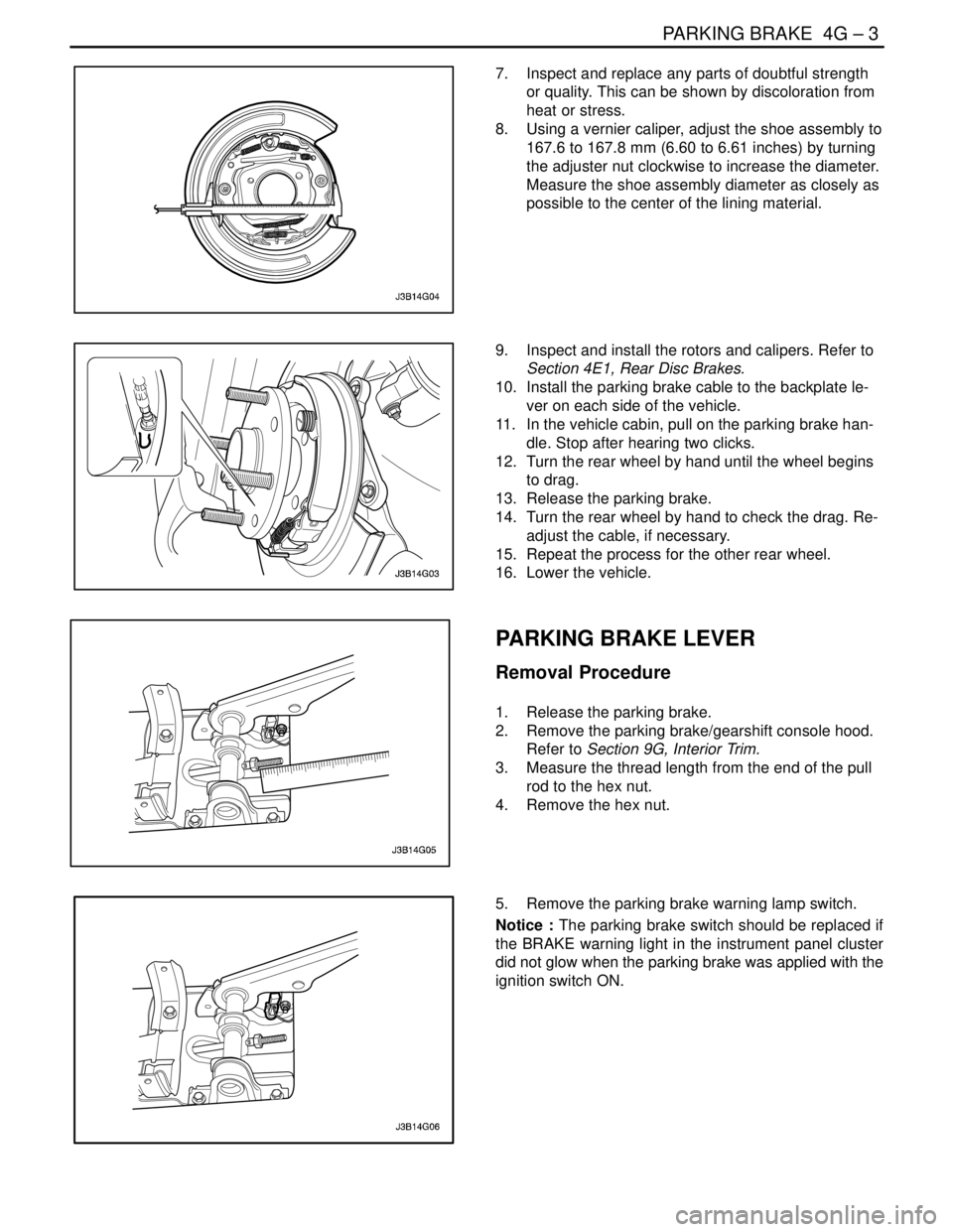
8. Using a vernier caliper, adjust the shoe assembly to
167.6 to 167.8 mm (6.60 to 6.61 inches) by turning
the adjuster nut clockwise to increase the diameter.
Measure the shoe assembly diameter as closely as
possible to the center of the lining material.
9. Inspect and install the rotors and calipers. Refer to
Section 4E1, Rear Disc Brakes.
10. Install the parking brake cable to the backplate le-
ver on each side of the vehicle.
11. In the vehicle cabin, pull on the parking brake han-
dle. Stop after hearing two clicks.
12. Turn the rear wheel by hand until the wheel begins
to drag.
13. Release the parking brake.
14. Turn the rear wheel by hand to check the drag. Re-
adjust the cable, if necessary.
15. Repeat the process for the other rear wheel.
16. Lower the vehicle.
PARKING BRAKE LEVER
Removal Procedure
1. Release the parking brake.
2. Remove the parking brake/gearshift console hood.
Refer to Section 9G, Interior Trim.
3. Measure the thread length from the end of the pull
rod to the hex nut.
4. Remove the hex nut.
5. Remove the parking brake warning lamp switch.
Notice : The parking brake switch should be replaced if
the BRAKE warning light in the instrument panel cluster
did not glow when the parking brake was applied with the
ignition switch ON.
Page 1156 of 2643
4G – 4IPARKING BRAKE
DAEWOO V–121 BL4
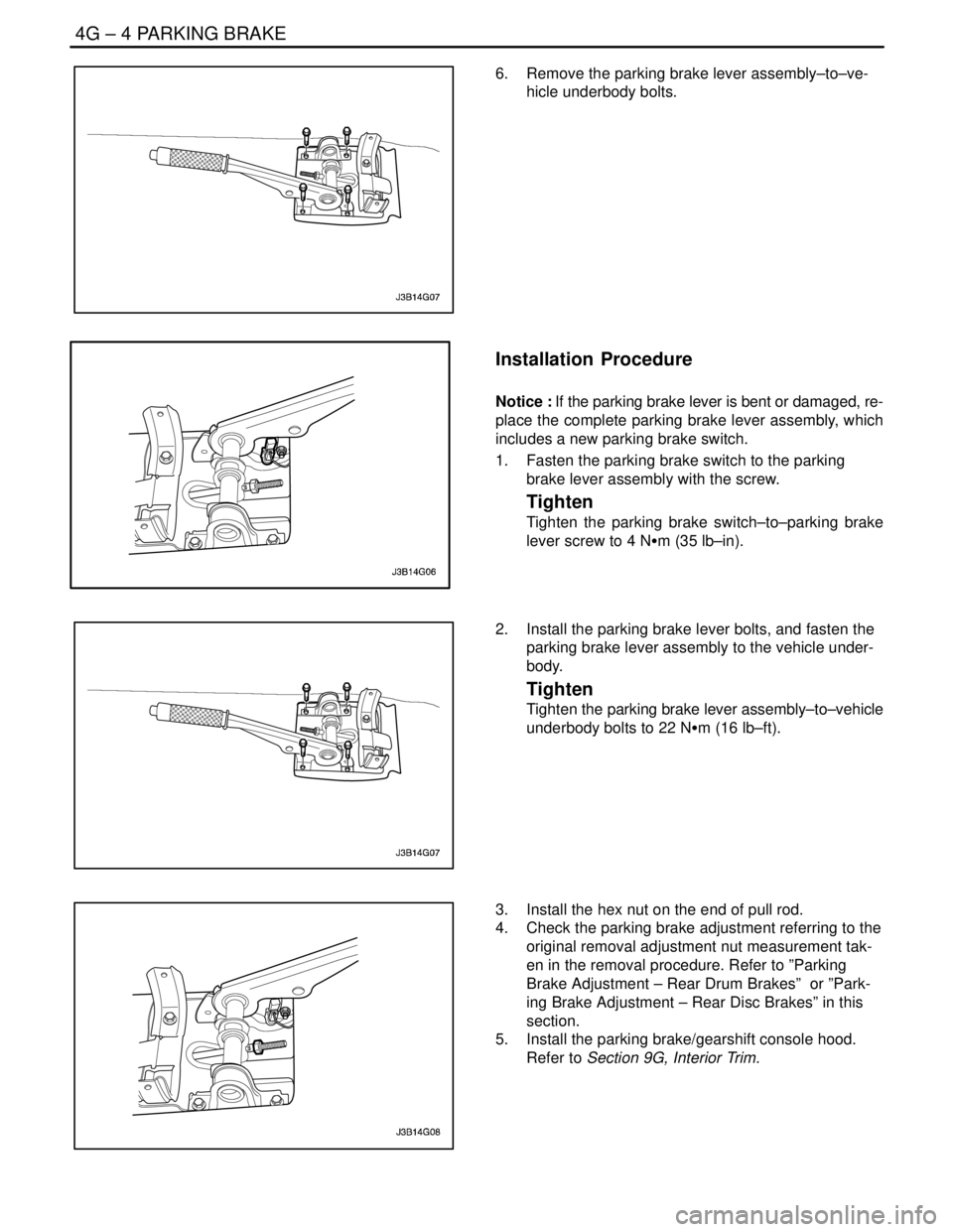
6. Remove the parking brake lever assembly–to–ve-
hicle underbody bolts.
Installation Procedure
Notice : If the parking brake lever is bent or damaged, re-
place the complete parking brake lever assembly, which
includes a new parking brake switch.
1. Fasten the parking brake switch to the parking
brake lever assembly with the screw.
Tighten
Tighten the parking brake switch–to–parking brake
lever screw to 4 NSm (35 lb–in).
2. Install the parking brake lever bolts, and fasten the
parking brake lever assembly to the vehicle under-
body.
Tighten
Tighten the parking brake lever assembly–to–vehicle
underbody bolts to 22 NSm (16 lb–ft).
3. Install the hex nut on the end of pull rod.
4. Check the parking brake adjustment referring to the
original removal adjustment nut measurement tak-
en in the removal procedure. Refer to ”Parking
Brake Adjustment – Rear Drum Brakes” or ”Park-
ing Brake Adjustment – Rear Disc Brakes” in this
section.
5. Install the parking brake/gearshift console hood.
Refer to Section 9G, Interior Trim.
Page 1157 of 2643
PARKING BRAKE 4G – 5
DAEWOO V–121 BL4
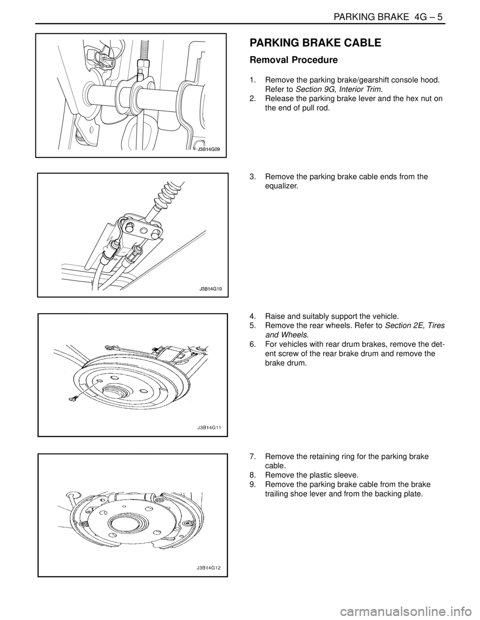
PARKING BRAKE CABLE
Removal Procedure
1. Remove the parking brake/gearshift console hood.
Refer to Section 9G, Interior Trim.
2. Release the parking brake lever and the hex nut on
the end of pull rod.
3. Remove the parking brake cable ends from the
equalizer.
4. Raise and suitably support the vehicle.
5. Remove the rear wheels. Refer to Section 2E, Tires
and Wheels.
6. For vehicles with rear drum brakes, remove the det-
ent screw of the rear brake drum and remove the
brake drum.
7. Remove the retaining ring for the parking brake
cable.
8. Remove the plastic sleeve.
9. Remove the parking brake cable from the brake
trailing shoe lever and from the backing plate.