2004 DAEWOO NUBIRA drain bolt
[x] Cancel search: drain boltPage 2039 of 2643
MANUAL CONTROL HEATING, VENTILATION AND AIR CONDITIONING SYSTEM 7B – 37
DAEWOO V–121 BL4
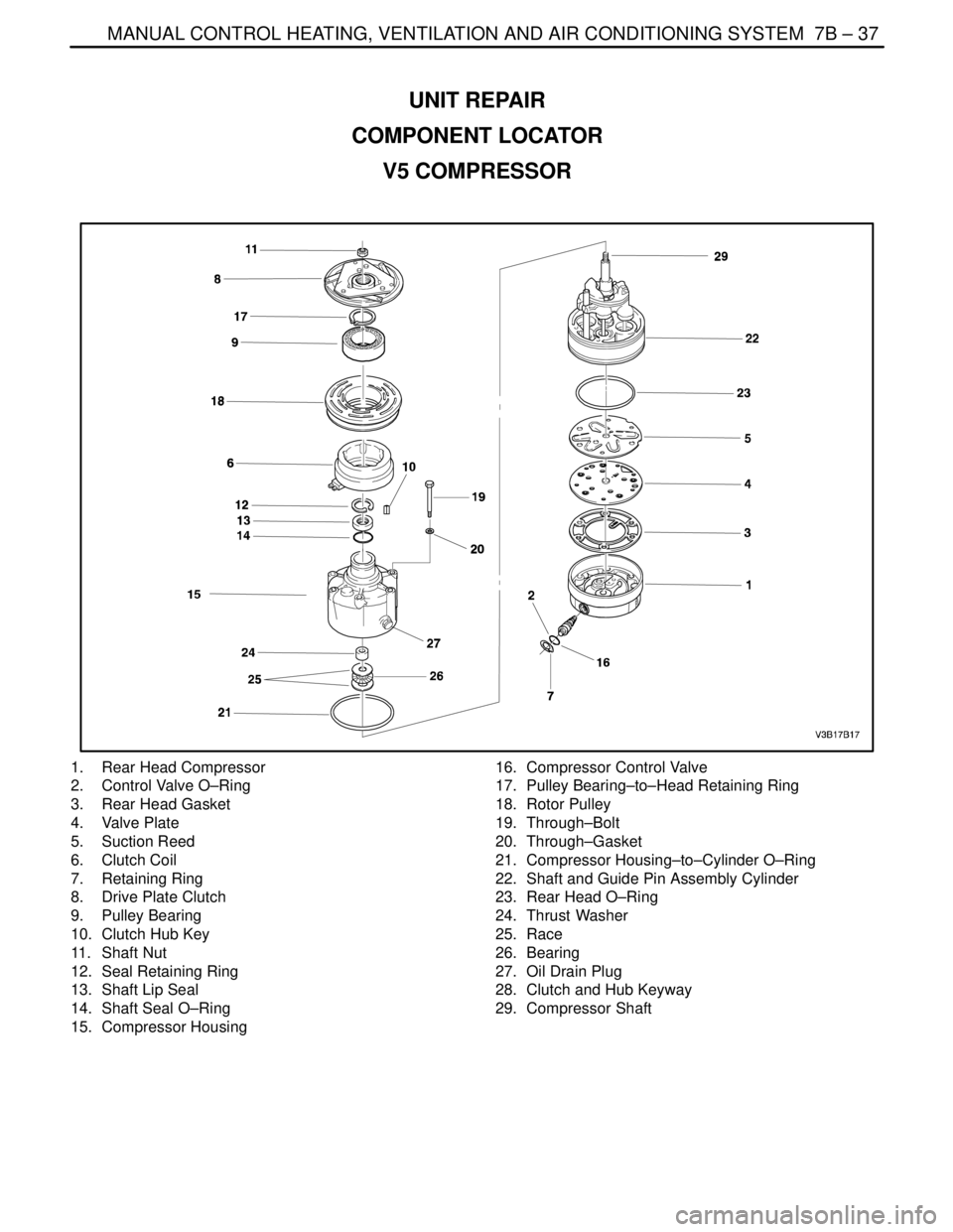
UNIT REPAIR
COMPONENT LOCATOR
V5 COMPRESSOR
1. Rear Head Compressor
2. Control Valve O–Ring
3. Rear Head Gasket
4. Valve Plate
5. Suction Reed
6. Clutch Coil
7. Retaining Ring
8. Drive Plate Clutch
9. Pulley Bearing
10. Clutch Hub Key
11. Shaft Nut
12. Seal Retaining Ring
13. Shaft Lip Seal
14. Shaft Seal O–Ring
15. Compressor Housing16. Compressor Control Valve
17. Pulley Bearing–to–Head Retaining Ring
18. Rotor Pulley
19. Through–Bolt
20. Through–Gasket
21. Compressor Housing–to–Cylinder O–Ring
22. Shaft and Guide Pin Assembly Cylinder
23. Rear Head O–Ring
24. Thrust Washer
25. Race
26. Bearing
27. Oil Drain Plug
28. Clutch and Hub Keyway
29. Compressor Shaft
Page 2049 of 2643
MANUAL CONTROL HEATING, VENTILATION AND AIR CONDITIONING SYSTEM 7B – 47
DAEWOO V–121 BL4
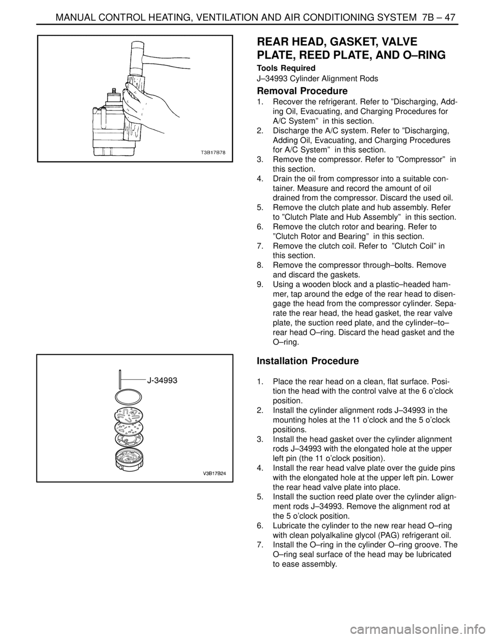
REAR HEAD, GASKET, VALVE
PLATE, REED PLATE, AND O–RING
Tools Required
J–34993 Cylinder Alignment Rods
Removal Procedure
1. Recover the refrigerant. Refer to ”Discharging, Add-
ing Oil, Evacuating, and Charging Procedures for
A/C System” in this section.
2. Discharge the A/C system. Refer to ”Discharging,
Adding Oil, Evacuating, and Charging Procedures
for A/C System” in this section.
3. Remove the compressor. Refer to ”Compressor” in
this section.
4. Drain the oil from compressor into a suitable con-
tainer. Measure and record the amount of oil
drained from the compressor. Discard the used oil.
5. Remove the clutch plate and hub assembly. Refer
to ”Clutch Plate and Hub Assembly” in this section.
6. Remove the clutch rotor and bearing. Refer to
”Clutch Rotor and Bearing” in this section.
7. Remove the clutch coil. Refer to ”Clutch Coil” in
this section.
8. Remove the compressor through–bolts. Remove
and discard the gaskets.
9. Using a wooden block and a plastic–headed ham-
mer, tap around the edge of the rear head to disen-
gage the head from the compressor cylinder. Sepa-
rate the rear head, the head gasket, the rear valve
plate, the suction reed plate, and the cylinder–to–
rear head O–ring. Discard the head gasket and the
O–ring.
Installation Procedure
1. Place the rear head on a clean, flat surface. Posi-
tion the head with the control valve at the 6 o’clock
position.
2. Install the cylinder alignment rods J–34993 in the
mounting holes at the 11 o’clock and the 5 o’clock
positions.
3. Install the head gasket over the cylinder alignment
rods J–34993 with the elongated hole at the upper
left pin (the 11 o’clock position).
4. Install the rear head valve plate over the guide pins
with the elongated hole at the upper left pin. Lower
the rear head valve plate into place.
5. Install the suction reed plate over the cylinder align-
ment rods J–34993. Remove the alignment rod at
the 5 o’clock position.
6. Lubricate the cylinder to the new rear head O–ring
with clean polyalkaline glycol (PAG) refrigerant oil.
7. Install the O–ring in the cylinder O–ring groove. The
O–ring seal surface of the head may be lubricated
to ease assembly.
Page 2050 of 2643
7B – 48IMANUAL CONTROL HEATING, VENTILATION AND AIR CONDITIONING SYSTEM
DAEWOO V–121 BL4
8. With the O–ring in place on the rear of the cylinder
assembly, locate the relief boss for the compressor
guide pin at the 6 o’clock position, directly above
the hole in the side of the rear head. Carefully lower
the cylinder and the front head assembly over the
guide pin to the rear head.
9. Press the cylinder and the compressor housing as-
sembly down onto the rear head using both hands.
10. Add the new through–bolt gasket to the through–
bolts and install it into the compressor assembly.
Four of the through–bolts must thread into the rear
head before removing the alignment rod.
Tighten
Alternately tighten the through–bolts in progressive
torque sequence to 10 NSm (89 lb–in).
11. Add new PAG refrigerant oil as determined in Step
1 of Removal Procedure.
12. Place the shaft nut on the shaft and rotate the com-
pressor shaft several times.
13. Perform a leak test on the compressor. Refer to
”Leak Testing (External)” in this section.
14. Install the clutch coil. Refer to ”Clutch Coil” in this
section.
15. Install the clutch rotor and bearing. Refer to ”Clutch
Rotor and Bearing” in this section.
16. Install the clutch plate and hub assembly. Refer to
”Clutch Plate and Hub Assembly” in this section.
17. Install the compressor. Refer to ”Compressor” in
this section.
18. Evacuate and recharge the A/C system. Refer to
”Discharging, Adding Oil, Evacuating, and Charging
Procedures for A/C System” in this section.
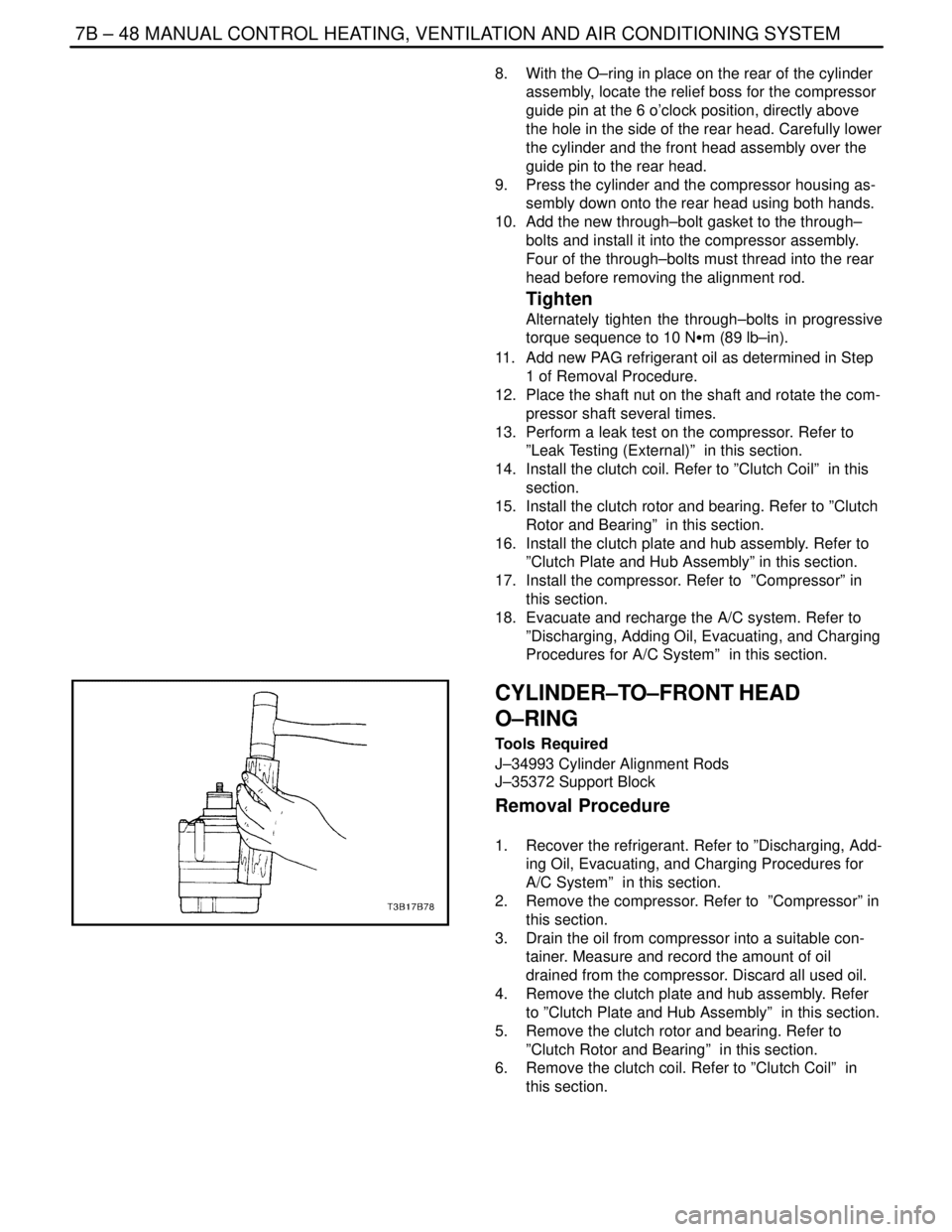
CYLINDER–TO–FRONT HEAD
O–RING
Tools Required
J–34993 Cylinder Alignment Rods
J–35372 Support Block
Removal Procedure
1. Recover the refrigerant. Refer to ”Discharging, Add-
ing Oil, Evacuating, and Charging Procedures for
A/C System” in this section.
2. Remove the compressor. Refer to ”Compressor” in
this section.
3. Drain the oil from compressor into a suitable con-
tainer. Measure and record the amount of oil
drained from the compressor. Discard all used oil.
4. Remove the clutch plate and hub assembly. Refer
to ”Clutch Plate and Hub Assembly” in this section.
5. Remove the clutch rotor and bearing. Refer to
”Clutch Rotor and Bearing” in this section.
6. Remove the clutch coil. Refer to ”Clutch Coil” in
this section.
Page 2051 of 2643
MANUAL CONTROL HEATING, VENTILATION AND AIR CONDITIONING SYSTEM 7B – 49
DAEWOO V–121 BL4
7. Remove and discard the shaft seal parts. Refer to
”Shaft Seal Replacement” in this section.
8. Remove the compressor through–bolts. Remove
and discard the gaskets.
9. Using a wooden block and a plastic–headed ham-
mer, tap the compressor housing at the mounting
locations to disengage the housing from the com-
pressor cylinder.
Important : Note the assembly sequence of the thrust
washer and bearing for ease of assembly.
10. Remove the thrust washer and the bearing.
11. Remove and discard the compressor housing–to–
cylinder O–ring.
Installation Procedure
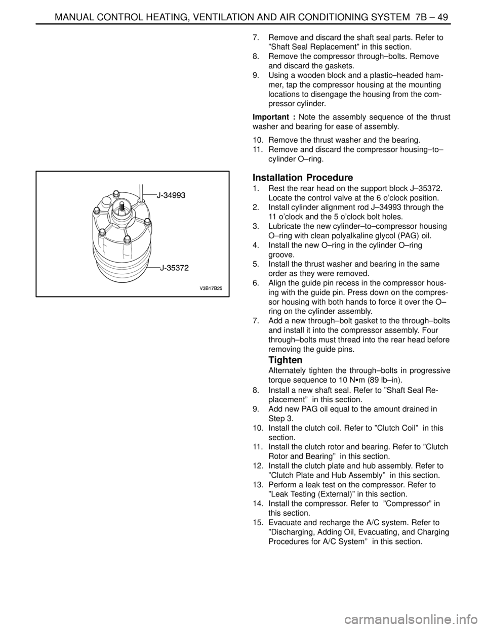
1. Rest the rear head on the support block J–35372.
Locate the control valve at the 6 o’clock position.
2. Install cylinder alignment rod J–34993 through the
11 o’clock and the 5 o’clock bolt holes.
3. Lubricate the new cylinder–to–compressor housing
O–ring with clean polyalkaline glycol (PAG) oil.
4. Install the new O–ring in the cylinder O–ring
groove.
5. Install the thrust washer and bearing in the same
order as they were removed.
6. Align the guide pin recess in the compressor hous-
ing with the guide pin. Press down on the compres-
sor housing with both hands to force it over the O–
ring on the cylinder assembly.
7. Add a new through–bolt gasket to the through–bolts
and install it into the compressor assembly. Four
through–bolts must thread into the rear head before
removing the guide pins.
Tighten
Alternately tighten the through–bolts in progressive
torque sequence to 10 NSm (89 lb–in).
8. Install a new shaft seal. Refer to ”Shaft Seal Re-
placement” in this section.
9. Add new PAG oil equal to the amount drained in
Step 3.
10. Install the clutch coil. Refer to ”Clutch Coil” in this
section.
11. Install the clutch rotor and bearing. Refer to ”Clutch
Rotor and Bearing” in this section.
12. Install the clutch plate and hub assembly. Refer to
”Clutch Plate and Hub Assembly” in this section.
13. Perform a leak test on the compressor. Refer to
”Leak Testing (External)” in this section.
14. Install the compressor. Refer to ”Compressor” in
this section.
15. Evacuate and recharge the A/C system. Refer to
”Discharging, Adding Oil, Evacuating, and Charging
Procedures for A/C System” in this section.
Page 2455 of 2643
9Q – 6IROOF
DAEWOO V–121 BL4
MAINTENANCE AND REPAIR
ON–VEHICLE SERVICE
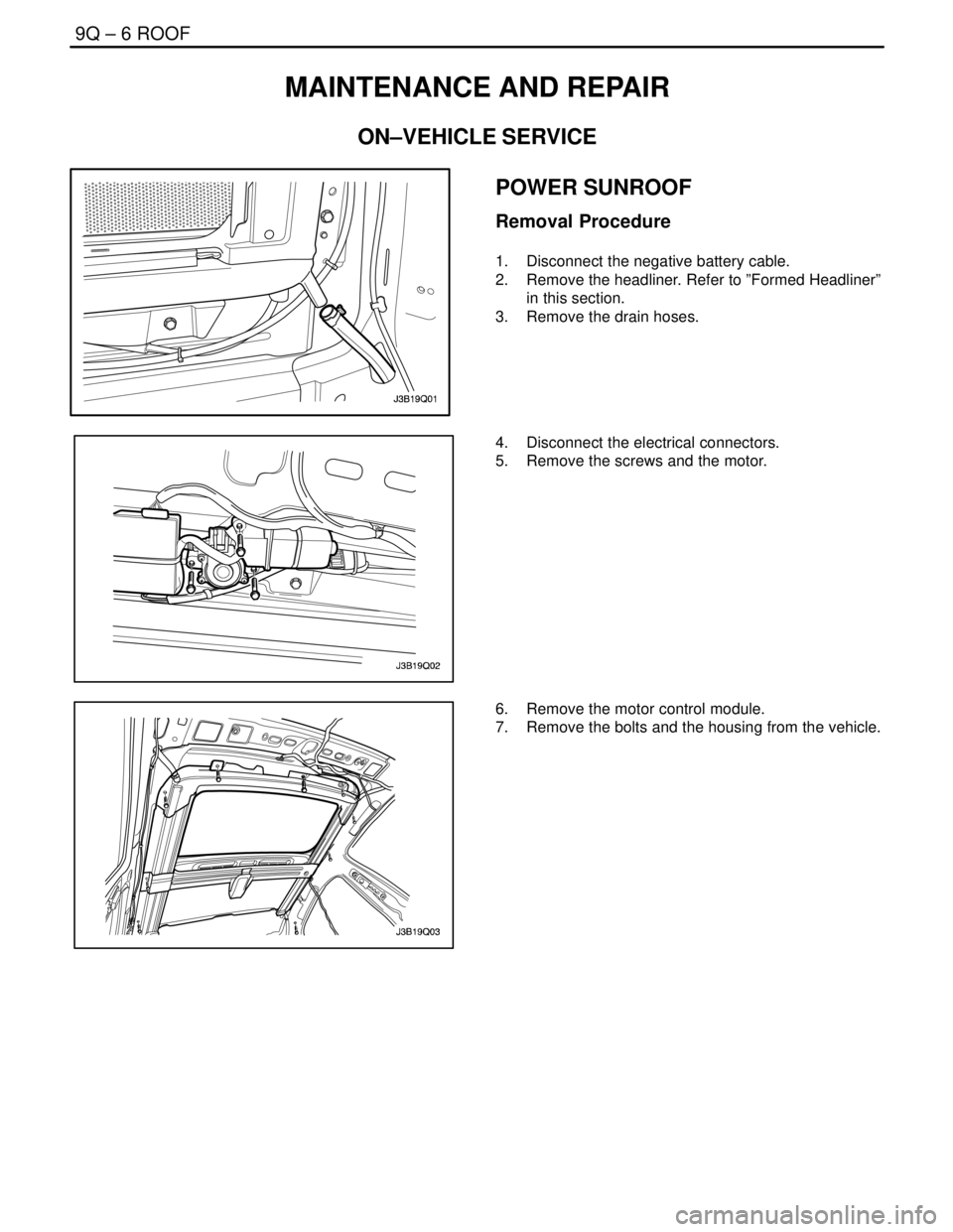
POWER SUNROOF
Removal Procedure
1. Disconnect the negative battery cable.
2. Remove the headliner. Refer to ”Formed Headliner”
in this section.
3. Remove the drain hoses.
4. Disconnect the electrical connectors.
5. Remove the screws and the motor.
6. Remove the motor control module.
7. Remove the bolts and the housing from the vehicle.
Page 2456 of 2643
ROOF 9Q – 7
DAEWOO V–121 BL4
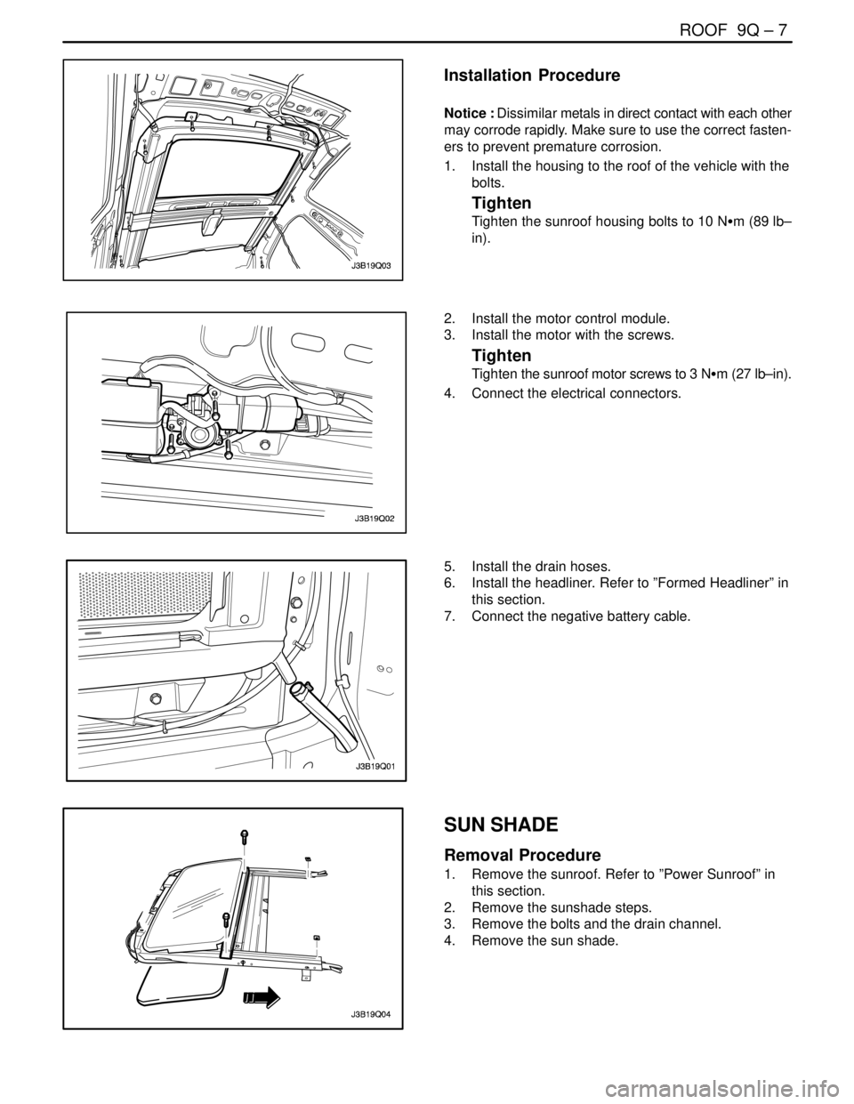
Installation Procedure
Notice : Dissimilar metals in direct contact with each other
may corrode rapidly. Make sure to use the correct fasten-
ers to prevent premature corrosion.
1. Install the housing to the roof of the vehicle with the
bolts.
Tighten
Tighten the sunroof housing bolts to 10 NSm (89 lb–
in).
2. Install the motor control module.
3. Install the motor with the screws.
Tighten
Tighten the sunroof motor screws to 3 NSm (27 lb–in).
4. Connect the electrical connectors.
5. Install the drain hoses.
6. Install the headliner. Refer to ”Formed Headliner” in
this section.
7. Connect the negative battery cable.
SUN SHADE
Removal Procedure
1. Remove the sunroof. Refer to ”Power Sunroof” in
this section.
2. Remove the sunshade steps.
3. Remove the bolts and the drain channel.
4. Remove the sun shade.
Page 2457 of 2643
9Q – 8IROOF
DAEWOO V–121 BL4
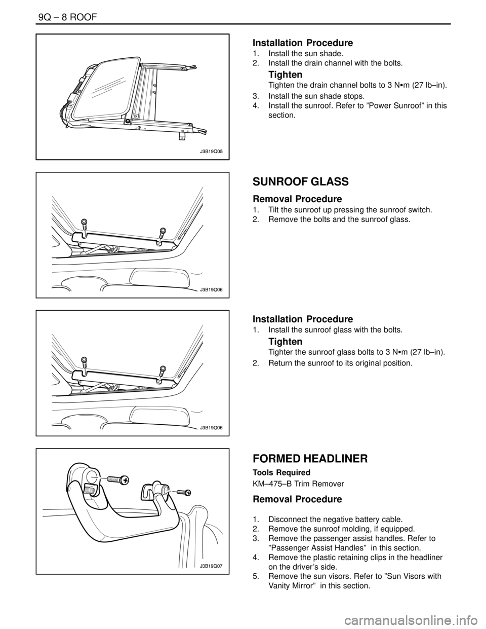
Installation Procedure
1. Install the sun shade.
2. Install the drain channel with the bolts.
Tighten
Tighten the drain channel bolts to 3 NSm (27 lb–in).
3. Install the sun shade stops.
4. Install the sunroof. Refer to ”Power Sunroof” in this
section.
SUNROOF GLASS
Removal Procedure
1. Tilt the sunroof up pressing the sunroof switch.
2. Remove the bolts and the sunroof glass.
Installation Procedure
1. Install the sunroof glass with the bolts.
Tighten
Tighter the sunroof glass bolts to 3 NSm (27 lb–in).
2. Return the sunroof to its original position.
FORMED HEADLINER
Tools Required
KM–475–B Trim Remover
Removal Procedure
1. Disconnect the negative battery cable.
2. Remove the sunroof molding, if equipped.
3. Remove the passenger assist handles. Refer to
”Passenger Assist Handles” in this section.
4. Remove the plastic retaining clips in the headliner
on the driver’s side.
5. Remove the sun visors. Refer to ”Sun Visors with
Vanity Mirror” in this section.