Page 1700 of 2643
5A2 – 110IAISIN AUTOMATIC TRANSAXLE
DAEWOO V–121 BL4
Installation Procedure
1. Install the fluid cooler inlet pipe fitting nut into the
transaxle.
Tighten
Tighten the fluid cooler inlet pipe fitting nut to 35 NSm
(26 Ib–ft).
2. Install the fluid cooler inlet pipe bolt into the trans-
axle.
Tighten
Tighten the fluid cooler inlet pipe bolt to 9 NSm (80 Ib–
in).
3. Install the inlet pipe union bolt into the radiator.
Tighten
Tighten the inlet pipe union bolt to 35 NSm (26 Ib–ft).
4. Connect the hose to inlet pipe and install the clip
into the hose.
5. Lower the vehicle.
6. Fill the transaxle with the fluid.
FLUID COOLER OUTLET PIPE AND
HOSES
Removal Procedure
1. Drain the transaxle fluid.
2. Remove the front outlet pipe union bolt from the
radiator.
3. Remove the clip from the hose.
4. Remove the rear outlet pipe clip bolt from the trans-
axle.
5. Remove the rear outlet pipe fitting nut from the
transaxle.
6. Remove the fluid cooler outlet pipe and hoses.
Page 1701 of 2643

AISIN AUTOMATIC TRANSAXLE 5A2 – 111
DAEWOO V–121 BL4
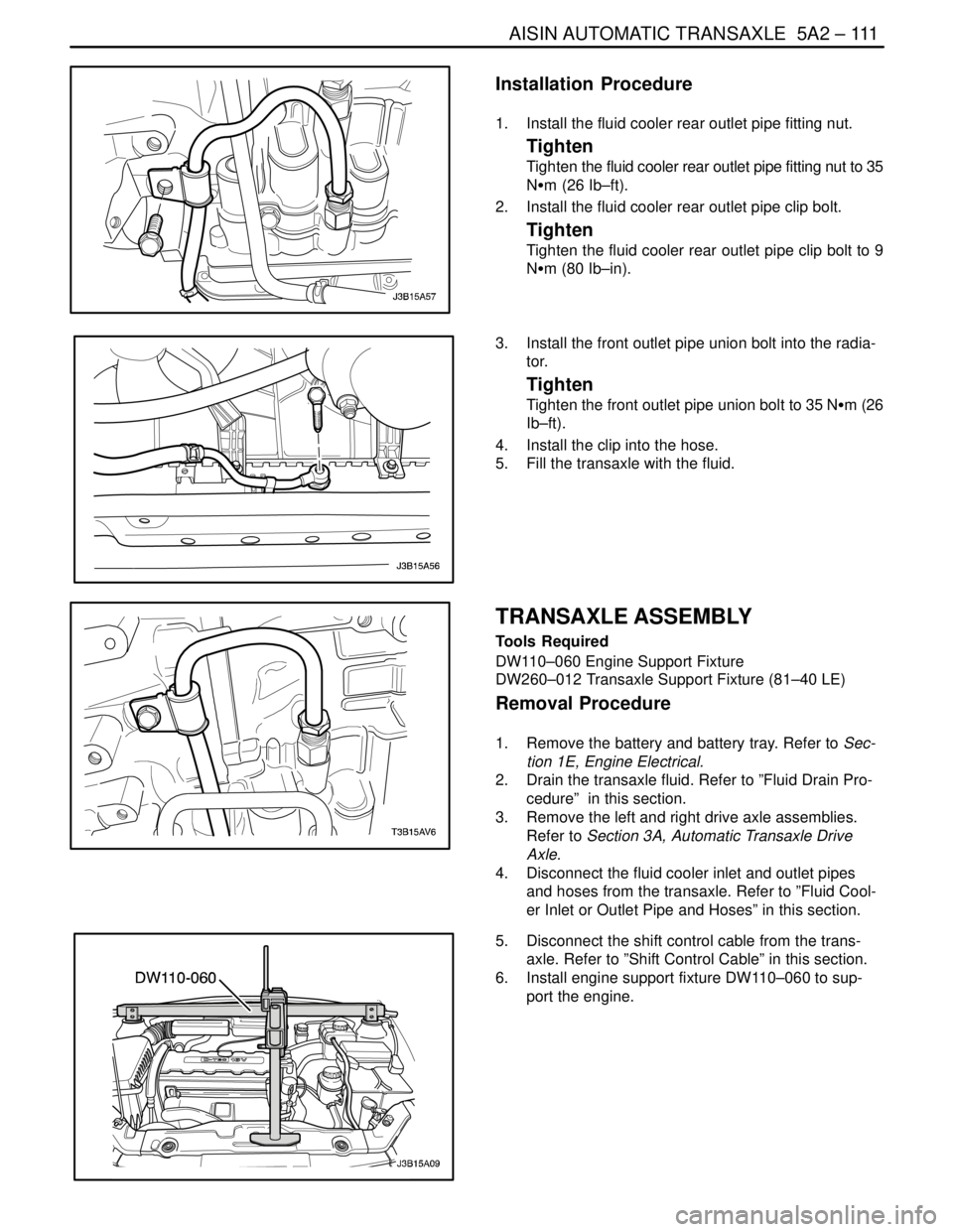
Installation Procedure
1. Install the fluid cooler rear outlet pipe fitting nut.
Tighten
Tighten the fluid cooler rear outlet pipe fitting nut to 35
NSm (26 Ib–ft).
2. Install the fluid cooler rear outlet pipe clip bolt.
Tighten
Tighten the fluid cooler rear outlet pipe clip bolt to 9
NSm (80 Ib–in).
3. Install the front outlet pipe union bolt into the radia-
tor.
Tighten
Tighten the front outlet pipe union bolt to 35 NSm (26
Ib–ft).
4. Install the clip into the hose.
5. Fill the transaxle with the fluid.
TRANSAXLE ASSEMBLY
Tools Required
DW110–060 Engine Support Fixture
DW260–012 Transaxle Support Fixture (81–40 LE)
Removal Procedure
1. Remove the battery and battery tray. Refer to Sec-
tion 1E, Engine Electrical.
2. Drain the transaxle fluid. Refer to ”Fluid Drain Pro-
cedure” in this section.
3. Remove the left and right drive axle assemblies.
Refer to Section 3A, Automatic Transaxle Drive
Axle.
4. Disconnect the fluid cooler inlet and outlet pipes
and hoses from the transaxle. Refer to ”Fluid Cool-
er Inlet or Outlet Pipe and Hoses” in this section.
5. Disconnect the shift control cable from the trans-
axle. Refer to ”Shift Control Cable” in this section.
6. Install engine support fixture DW110–060 to sup-
port the engine.
Page 1708 of 2643
5A2 – 118IAISIN AUTOMATIC TRANSAXLE
DAEWOO V–121 BL4
8. Remove the screw plug from the transaxle case.
9. Remove the O–ring from the screw plug.
10. Remove the bolt and the input shaft speed (ISS)
sensor.
11. Remove the breather plug.
12. Remove the O–ring from the breather plug.
13. Remove the bolt and the output shaft speed (OSS)
sensor.
14. Remove the 18 bolts.
15. Remove the oil pan and gasket.
16. Remove the drain plug from the oil pan.
Page 1839 of 2643
FIVE–SPEED MANUAL TRANSAXLE 5B – 15
DAEWOO V–121 BL4
MAINTENANCE AND REPAIR
ON–VEHICLE SERVICE
CHECKING FLUID LEVEL
1. With the vehicle on a level surface and the fluid in
the transaxle cold, remove the filler plug and check
the fluid level. The fluid should come to the bottom
edge of the plug hole.
2. If the level is low, add SAE 80 manual transaxle
fluid through the filler plug hole until the fluid begins
to run out.
3. Reinstall the filler plug and tighten it securely.
4. If the fluid is contaminated, drain the oil after re-
moving the differential gear cover.
SHIFT LINKAGE ADJUSTMENT
(LEFT–HAND DRIVE SHOWN,
RIGHT–HAND DRIVE SIMILAR)
1. Disconnect the negative battery cable.
2. Position the gearshift lever into NEUTRAL.
Important : All the gears must be easy to engage when
the vehicle is stationary, the engine is running, and the
clutch is disengaged.
3. Loosen the rod clamp bolt.
Page 1914 of 2643

POWER STEERING PUMP 6B – 5
DAEWOO V–121 BL4
3. Position a drain pan to catch the power steering
fluid that will drain from the high–pressure hose af-
ter it is disconnected from the power steering
pump.
4. Disconnect the high–pressure hose fitting from the
power steering pump.
5. Position a drain pan to catch the power steering
fluid that will drain from the supply hose after it is
disconnected from the power steering pump.
6. Disconnect the supply hose from the power steer-
ing pump.
7. Remove the bolt from the front right side of the
power steering pump.
8. Remove the two power steering pump bolts and
remove the power steering pump from the vehicle.
Installation Procedure
1. Install the power steering pump into the vehicle and
install the two power steering pump bolts.
Tighten
Tighten the two power steering pump bolts to 25 NSm
(18 lb–ft).
2. Swing the power steering pump bracket down and
install the front right side bolt.
Tighten
Tighten the both of the right side power steering pump
bracket bolts to 35 NSm (26 lb–ft).
Page 1928 of 2643
POWER STEERING GEAR 6C – 11
DAEWOO V–121 BL4
MAINTENANCE AND REPAIR
ON–VEHICLE SERVICE
RACK AND PINION ASSEMBLY
(Left–Hand Drive Shown, Right–Hand Drive
Similar)
Tools Required
KM–507–B Ball Joint Remover
Removal Procedure
1. Disconnect the negative battery cable.
2. Raise and suitably support the vehicle.
3. Remove the wheels. Refer to Section 2E, Tires and
Wheels.
4. Disconnect the power steering gear fluid outlet
pipe. Place a drain pan under the steering gear to
catch the power steering fluid.
5. Disconnect the power steering gear fluid inlet pipe.
6. Position the steering gear straight ahead by turning
the steering wheel until the steering wheel spokes
are vertical and pointed to the left.
7. Scribe a mark on the stub shaft housing that lines
up with a mark on the intermediate shaft lower cou-
pling.
8. Remove the intermediate shaft pinch bolt.
Page 2035 of 2643

MANUAL CONTROL HEATING, VENTILATION AND AIR CONDITIONING SYSTEM 7B – 33
DAEWOO V–121 BL4
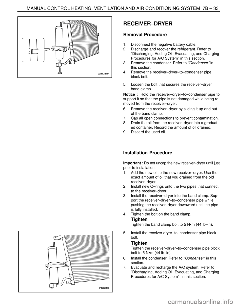
RECEIVER–DRYER
Removal Procedure
1. Disconnect the negative battery cable.
2. Discharge and recover the refrigerant. Refer to
”Discharging, Adding Oil, Evacuating, and Charging
Procedures for A/C System” in this section.
3. Remove the condenser. Refer to ”Condenser” in
this section.
4. Remove the receiver–dryer–to–condenser pipe
block bolt.
5. Loosen the bolt that secures the receiver–dryer
band clamp.
Notice : Hold the receiver–dryer–to–condenser pipe to
support it so that the pipe is not damaged while being re-
moved from the receiver–dryer.
6. Remove the receiver–dryer by sliding it up and out
of the band clamp.
7. Cap all open connections to prevent contamination.
8. Drain the oil from the receiver–dryer into a graduat-
ed container. Record the amount of oil drained.
9. Discard the used oil.
Installation Procedure
Important : Do not uncap the new receiver–dryer until just
prior to installation.
1. Add the new oil to the new receiver–dryer. Use the
exact amount of oil that you drained from the old
receiver–dryer.
2. Install new O–rings onto the two pipes that connect
to the receiver–dryer.
3. Install the receiver–dryer into the band clamp. Sup-
port the receiver–dryer–to–condenser pipe while
pushing the receiver–dryer downward until the pipe
is fully installed.
4. Tighten the bolt on the band clamp.
Tighten
Tighten the band clamp bolt to 5 NSm (44 lb–in).
5. Install the receiver dryer–to–condenser pipe block
bolt.
Tighten
Tighten the receiver–dryer–to–condenser pipe block
bolt to 5 NSm (44 lb–in).
6. Install the condenser. Refer to ”Condenser” in this
section.
7. Evacuate and recharge the A/C system. Refer to
”Discharging, Adding Oil, Evacuating, and Charging
Procedures for A/C System” in this section.
Page 2036 of 2643

7B – 34IMANUAL CONTROL HEATING, VENTILATION AND AIR CONDITIONING SYSTEM
DAEWOO V–121 BL4
COMPRESSOR
Removal Procedure
1. Disconnect the negative battery cable.
2. Discharge and recover the refrigerant. Refer to
”Discharging, Adding Oil, Evacuating, and Charging
Procedures for A/C System” in this section.
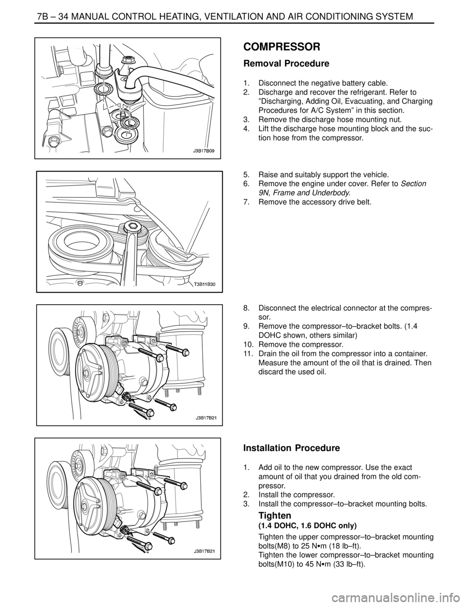
3. Remove the discharge hose mounting nut.
4. Lift the discharge hose mounting block and the suc-
tion hose from the compressor.
5. Raise and suitably support the vehicle.
6. Remove the engine under cover. Refer to Section
9N, Frame and Underbody.
7. Remove the accessory drive belt.
8. Disconnect the electrical connector at the compres-
sor.
9. Remove the compressor–to–bracket bolts. (1.4
DOHC shown, others similar)
10. Remove the compressor.
11. Drain the oil from the compressor into a container.
Measure the amount of the oil that is drained. Then
discard the used oil.
Installation Procedure
1. Add oil to the new compressor. Use the exact
amount of oil that you drained from the old com-
pressor.
2. Install the compressor.
3. Install the compressor–to–bracket mounting bolts.
Tighten
(1.4 DOHC, 1.6 DOHC only)
Tighten the upper compressor–to–bracket mounting
bolts(M8) to 25 NSm (18 lb–ft).
Tighten the lower compressor–to–bracket mounting
bolts(M10) to 45 NSm (33 lb–ft).