Page 205 of 2643

1D – 10IENGINE COOLING
DAEWOO V–121 BL4
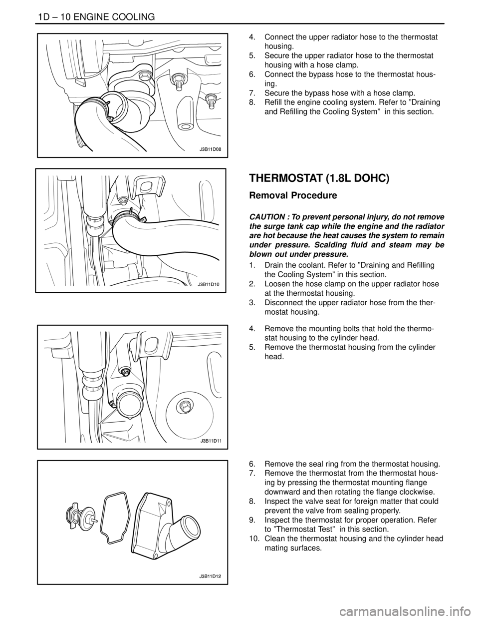
4. Connect the upper radiator hose to the thermostat
housing.
5. Secure the upper radiator hose to the thermostat
housing with a hose clamp.
6. Connect the bypass hose to the thermostat hous-
ing.
7. Secure the bypass hose with a hose clamp.
8. Refill the engine cooling system. Refer to ”Draining
and Refilling the Cooling System” in this section.
THERMOSTAT (1.8L DOHC)
Removal Procedure
CAUTION : To prevent personal injury, do not remove
the surge tank cap while the engine and the radiator
are hot because the heat causes the system to remain
under pressure. Scalding fluid and steam may be
blown out under pressure.
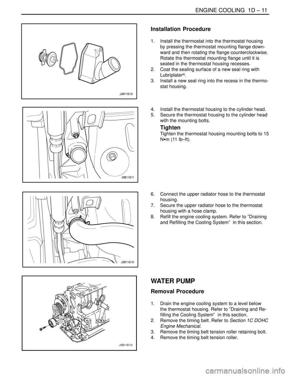
1. Drain the coolant. Refer to ”Draining and Refilling
the Cooling System” in this section.
2. Loosen the hose clamp on the upper radiator hose
at the thermostat housing.
3. Disconnect the upper radiator hose from the ther-
mostat housing.
4. Remove the mounting bolts that hold the thermo-
stat housing to the cylinder head.
5. Remove the thermostat housing from the cylinder
head.
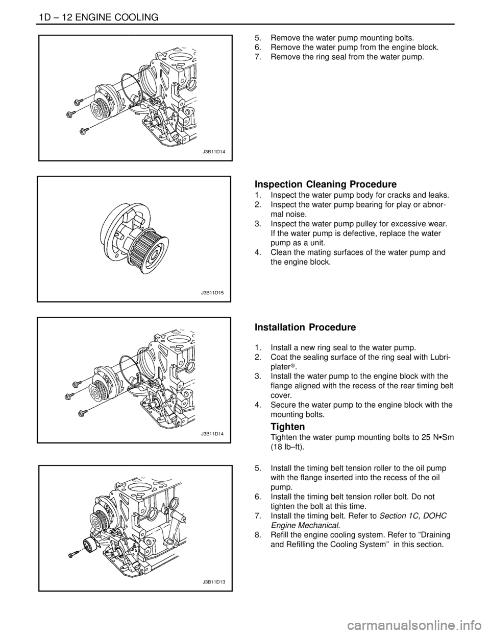
6. Remove the seal ring from the thermostat housing.
7. Remove the thermostat from the thermostat hous-
ing by pressing the thermostat mounting flange
downward and then rotating the flange clockwise.
8. Inspect the valve seat for foreign matter that could
prevent the valve from sealing properly.
9. Inspect the thermostat for proper operation. Refer
to ”Thermostat Test” in this section.
10. Clean the thermostat housing and the cylinder head
mating surfaces.
Page 206 of 2643

ENGINE COOLING 1D – 11
DAEWOO V–121 BL4
Installation Procedure
1. Install the thermostat into the thermostat housing
by pressing the thermostat mounting flange down-
ward and then rotating the flange counterclockwise.
Rotate the thermostat mounting flange until it is
seated in the thermostat housing recesses.
2. Coat the sealing surface of a new seal ring with
Lubriplater®.
3. Install a new seal ring into the recess in the thermo-
stat housing.
4. Install the thermostat housing to the cylinder head.
5. Secure the thermostat housing to the cylinder head
with the mounting bolts.
Tighten
Tighten the thermostat housing mounting bolts to 15
NSm (11 lb–ft).
6. Connect the upper radiator hose to the thermostat
housing.
7. Secure the upper radiator hose to the thermostat
housing with a hose clamp.
8. Refill the engine cooling system. Refer to ”Draining
and Refilling the Cooling System” in this section.
WATER PUMP
Removal Procedure
1. Drain the engine cooling system to a level below
the thermostat housing. Refer to ”Draining and Re-
filling the Cooling System” in this section.
2. Remove the timing belt. Refer to Section 1C DOHC
Engine Mechanical.
3. Remove the timing belt tension roller retaining bolt.
4. Remove the timing belt tension roller.
Page 207 of 2643

1D – 12IENGINE COOLING
DAEWOO V–121 BL4
5. Remove the water pump mounting bolts.
6. Remove the water pump from the engine block.
7. Remove the ring seal from the water pump.
Inspection Cleaning Procedure
1. Inspect the water pump body for cracks and leaks.
2. Inspect the water pump bearing for play or abnor-
mal noise.
3. Inspect the water pump pulley for excessive wear.
If the water pump is defective, replace the water
pump as a unit.
4. Clean the mating surfaces of the water pump and
the engine block.
Installation Procedure
1. Install a new ring seal to the water pump.
2. Coat the sealing surface of the ring seal with Lubri-
plater®.
3. Install the water pump to the engine block with the
flange aligned with the recess of the rear timing belt
cover.
4. Secure the water pump to the engine block with the
mounting bolts.
Tighten
Tighten the water pump mounting bolts to 25 NSSm
(18 lb–ft).
5. Install the timing belt tension roller to the oil pump
with the flange inserted into the recess of the oil
pump.
6. Install the timing belt tension roller bolt. Do not
tighten the bolt at this time.
7. Install the timing belt. Refer to Section 1C, DOHC
Engine Mechanical.
8. Refill the engine cooling system. Refer to ”Draining
and Refilling the Cooling System” in this section.
Page 209 of 2643

1D – 14IENGINE COOLING
DAEWOO V–121 BL4
Tighten
Tighten the fan motor retaining screws to 4 NSm (35
lb–in).
3. Turn over the fan shroud assembly.
4. Install the fan to the fan shroud assembly with the
single nut in the center of the fan hub.
Tighten
Tighten the fan motor nut to 3.2 NSm (28 lb–in).
5. Install the fan shroud assembly to the radiator.
Important : Be careful to seat the mounting post on the
fan shroud into the socket at the radiator left tank. Be sure
to slip the tab at the bottom edge of the shroud into the re-
taining clip near the center of the radiator.
6. Secure the shroud to the top of the radiator with the
mounting bolts.
Tighten
Tighten the fan assembly mounting bolts to 4 NSm (35
lb–in).
7. Connect the cooling fan electrical connector.
8. Connect the negative battery cable.
SURGE TANK
Removal Procedure
CAUTION : To prevent personal injury, do not remove
the surge tank cap while the engine and the radiator
are hot, because the heat causes the system to re-
main under pressure. Scalding fluid and steam may
be blown out under pressure.
1. Drain the engine coolant to below the level of the
surge tank.
2. Loosen the return hose clamp and disconnect the
return hose from the top of the surge tank.
Page 211 of 2643

1D – 16IENGINE COOLING
DAEWOO V–121 BL4
RADIATOR
Removal Procedure
1. Disconnect the negative battery cable.
2. Drain the engine cooling system. Refer to ”Draining
and Refilling the Cooling System” in this section.
3. Remove the main and the auxiliary cooling fans.
Refer to ”Electric Cooling Fan – Main or Auxiliary”
in this section.
4. Remove the upper radiator retaining bolt.
5. Remove the upper radiator retaining bracket.
6. Remove the upper radiator hose clamp.
7. Disconnect the upper radiator hose from the radia-
tor.
8. Remove the hose clamp from the surge tank hose
at the radiator.
9. Disconnect the surge tank hose from the radiator.
10. Remove the lower radiator hose clamp.
11. Disconnect the lower radiator hose from the radia-
tor.
12. Disconnect the transaxle cooler pipes from the low-
er radiator tank, if equipped.
13. Remove the bolt and the transaxle pipe support
clamp from the radiator.
14. Remove the radiator from the vehicle.
Important : The radiator still contains a substantial
amount of coolant. Drain the remainder of the coolant from
the radiator into a drain pan.
Installation Procedure
1. Set the radiator into place in the vehicle with the
radiator bottom posts in the rubber shock bumpers.
2. Connect the transaxle cooler pipes to the lower ra-
diator tank, if equipped.
3. Install the transaxle pipe and support clamp to the
radiator with a bolt.
4. Connect the surge tank hose to the radiator.
5. Secure the surge tank hose with a hose clamp.
6. Connect the upper radiator hose and the lower ra-
diator hose to the radiator.
7. Secure each hose with a hose clamp.
8. Position the radiator retainers in place.
9. Install the upper radiator retainer bracket.
10. Install the upper radiator retaining bolt.
Page 212 of 2643
ENGINE COOLING 1D – 17
DAEWOO V–121 BL4
11. Install the main and the auxiliary cooling fans. Refer
to ”Electric Cooling Fan – Main or Auxiliary” in this
section.
12. Refill the engine cooling system. Refer to ”Draining
and Refilling the Cooling System” in this section.
13. Connect the negative battery cable.
Tighten
Tighten the radiator retaining bolt to 8 NSm (71 lb–in).
Page 994 of 2643

AUTOMATIC TRANSAXLE DRIVE AXLE 3A – 5
DAEWOO V–121 BL4
8. Remove the damping block connection nut and
bolt.
9. Remove the rear mounting bracket bolts and the
bracket.
10. Push the drive axle shaft from the wheel hub.
Important : Support the unfastened end of the drive axle.
Do not allow the drive axle to dangle freely from the trans-
axle for any length of time after it has been removed from
the wheel hub.
Important : Place a drain pan below the transaxle to catch
the escaping fluid. Cap the transaxle drive opening after
the drive axle has been removed to keep the fluid in and
any contamination out.
11. Remove the drive axle from the transaxle using the
axle shaft remover DW340–110.
Installation Procedure
Notice : Do not damage the seals.
1. Clean the hub seal and the transaxle seal.
2. Install the drive axle into the transaxle.
3. Install the wheel hub onto the axle shaft.
4. Install the rear mounting bracket bolts and the bra-
ket.
Tighten
Tighten the rear mounting bracket bolts to 62 NSm (45
lb–ft).
5. Install the damping block connection nut and bolt.
Tighten
Tighten the damping block connection nut and bolt to
68 NSm (50 lb–ft).
Page 1005 of 2643

3B – 6IMANUAL TRANSAXLE DRIVE AXLE
DAEWOO V–121 BL4
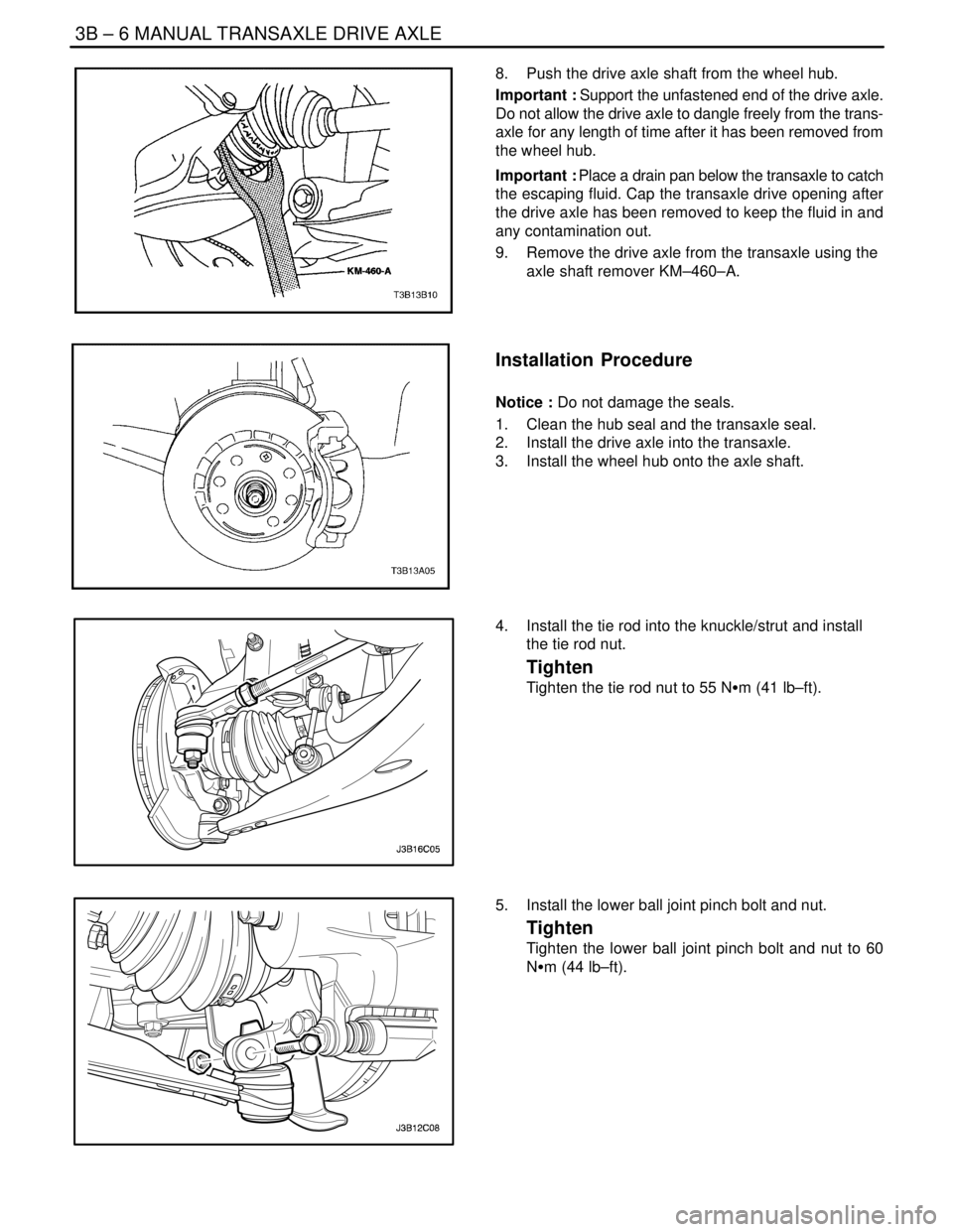
8. Push the drive axle shaft from the wheel hub.
Important : Support the unfastened end of the drive axle.
Do not allow the drive axle to dangle freely from the trans-
axle for any length of time after it has been removed from
the wheel hub.
Important : Place a drain pan below the transaxle to catch
the escaping fluid. Cap the transaxle drive opening after
the drive axle has been removed to keep the fluid in and
any contamination out.
9. Remove the drive axle from the transaxle using the
axle shaft remover KM–460–A.
Installation Procedure
Notice : Do not damage the seals.
1. Clean the hub seal and the transaxle seal.
2. Install the drive axle into the transaxle.
3. Install the wheel hub onto the axle shaft.
4. Install the tie rod into the knuckle/strut and install
the tie rod nut.
Tighten
Tighten the tie rod nut to 55 NSm (41 lb–ft).
5. Install the lower ball joint pinch bolt and nut.
Tighten
Tighten the lower ball joint pinch bolt and nut to 60
NSm (44 lb–ft).