2004 DAEWOO NUBIRA battery
[x] Cancel search: batteryPage 164 of 2643

1C2 – 44I1.8L DOHC ENGINE MECHANICAL
DAEWOO V–121 BL4
3. Install the exhaust camshaft gear.
4. While holding the exhaust camshaft firmly in place,
install the exhaust camshaft gear bolt.
Tighten
Tighten the exhaust camshaft gear bolt to 50 NSm (37
lb–ft) plus 60 degrees and 15 degrees using the angu-
lar torque gauge KM–470–B.
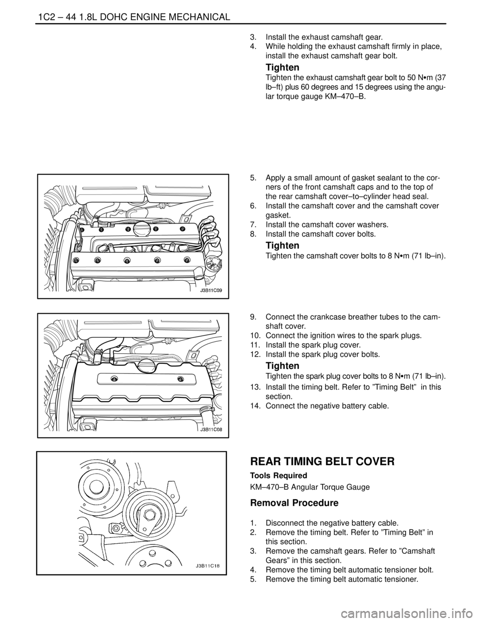
5. Apply a small amount of gasket sealant to the cor-
ners of the front camshaft caps and to the top of
the rear camshaft cover–to–cylinder head seal.
6. Install the camshaft cover and the camshaft cover
gasket.
7. Install the camshaft cover washers.
8. Install the camshaft cover bolts.
Tighten
Tighten the camshaft cover bolts to 8 NSm (71 lb–in).
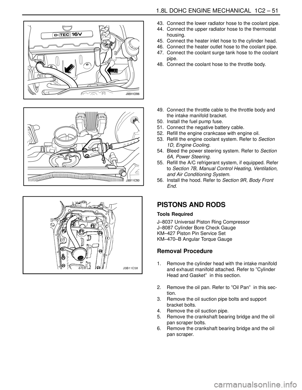
9. Connect the crankcase breather tubes to the cam-
shaft cover.
10. Connect the ignition wires to the spark plugs.
11. Install the spark plug cover.
12. Install the spark plug cover bolts.
Tighten
Tighten the spark plug cover bolts to 8 NSm (71 lb–in).
13. Install the timing belt. Refer to ”Timing Belt” in this
section.
14. Connect the negative battery cable.
REAR TIMING BELT COVER
Tools Required
KM–470–B Angular Torque Gauge
Removal Procedure
1. Disconnect the negative battery cable.
2. Remove the timing belt. Refer to ”Timing Belt” in
this section.
3. Remove the camshaft gears. Refer to ”Camshaft
Gears” in this section.
4. Remove the timing belt automatic tensioner bolt.
5. Remove the timing belt automatic tensioner.
Page 166 of 2643

1C2 – 46I1.8L DOHC ENGINE MECHANICAL
DAEWOO V–121 BL4
7. Install the timing belt automatic tensioner and bolt.
8. Install the camshaft gears. Refer to ”Camshaft
Gears” in this section.
9. Install the timing belt and timing belt cover. Refer to
”Timing Belt” in this section.
10. Connect the negative battery cable.
ENGINE
Removal Procedure
1. Remove the fuel pump fuse.
2. Start the engine. After it stalls, crank the engine for
10 seconds to rid the fuel system of fuel pressure.
3. Remove the hood. Refer to Section 9R, Body Front
End.
4. Drain the engine oil.
5. Disconnect the negative battery cable.
6. Discharge the air conditioning (A/C) system, if
equipped. Refer to Section 7B, Manual Control
Heating, Ventilation, and Air Conditioning Systems.
7. Disconnect the manifold air temperature (MAT)
sensor connector.
8. Remove the air cleaner outlet hose from the throttle
body and air cleaner housing.
9. Disconnect the breather tubes from the camshaft
cover.
10. Remove the right front wheel. Refer to Section 2E,
Tires and Wheels.
11. Remove the right front wheel well splash shield.
Refer to Section 9R, Body Font End.
12. Remove the serpentine accessory drive belt. Refer
to Section 6B, Power Steering Pump.
13. Drain the engine coolant. Refer to Section 1D, En-
gine Cooling.
14. Remove the cooling system radiator and the engine
cooling fans. Refer to Section 1D, Engine Cooling.
15. Disconnect the upper radiator hose from the ther-
mostat housing.
16. Disconnect the power steering return hose from the
power steering pump.
17. Disconnect the power steering pressure hose from
the power steering pump.
18. Disconnect the electrical connector at the direct
ignition system (DIS) coil and the electronic control
module (ECM) ground terminal and at the starter
motor.
Page 171 of 2643

1.8L DOHC ENGINE MECHANICAL 1C2 – 51
DAEWOO V–121 BL4
43. Connect the lower radiator hose to the coolant pipe.
44. Connect the upper radiator hose to the thermostat
housing.
45. Connect the heater inlet hose to the cylinder head.
46. Connect the heater outlet hose to the coolant pipe.
47. Connect the coolant surge tank hose to the coolant
pipe.
48. Connect the coolant hose to the throttle body.
49. Connect the throttle cable to the throttle body and
the intake manifold bracket.
50. Install the fuel pump fuse.
51. Connect the negative battery cable.
52. Refill the engine crankcase with engine oil.
53. Refill the engine coolant system. Refer to Section
1D, Engine Cooling.
54. Bleed the power steering system. Refer to Section
6A, Power Steering.
55. Refill the A/C refrigerant system, if equipped. Refer
to Section 7B, Manual Control Heating, Ventilation,
and Air Conditioning System.
56. Install the hood. Refer to Section 9R, Body Front
End.
PISTONS AND RODS
Tools Required
J–8037 Universal Piston Ring Compressor
J–8087 Cylinder Bore Check Gauge
KM–427 Piston Pin Service Set
KM–470–B Angular Torque Gauge
Removal Procedure
1. Remove the cylinder head with the intake manifold
and exhaust manifold attached. Refer to ”Cylinder
Head and Gasket” in this section.
2. Remove the oil pan. Refer to ”Oil Pan” in this sec-
tion.
3. Remove the oil suction pipe bolts and support
bracket bolts.
4. Remove the oil suction pipe.
5. Remove the crankshaft bearing bridge and the oil
pan scraper bolts.
6. Remove the crankshaft bearing bridge and the oil
pan scraper.
Page 196 of 2643

SECTION : 1D
ENGINE COOLING
CAUTION : Disconnect the negative battery cable before removing or installing any electrical unit or when a tool
or equipment could easily come in contact with exposed electrical terminals. Disconnecting this cable will help
prevent personal injury and damage to the vehicle. The ignition must also be in LOCK unless otherwise noted.
TABLE OF CONTENTS
SPECIFICATIONS1D–2 . . . . . . . . . . . . . . . . . . . . . . . . . .
Capacity 1D–2. . . . . . . . . . . . . . . . . . . . . . . . . . . . . . . . . .
Fastener Tightening Specifications 1D–2. . . . . . . . . . .
SPECIAL TOOLS1D–2 . . . . . . . . . . . . . . . . . . . . . . . . . . .
Special Tools Table 1D–2. . . . . . . . . . . . . . . . . . . . . . . .
DIAGNOSIS1D–3 . . . . . . . . . . . . . . . . . . . . . . . . . . . . . . . .
Thermostat Test 1D–3. . . . . . . . . . . . . . . . . . . . . . . . . . .
Surge Tank Cap Test 1D–3. . . . . . . . . . . . . . . . . . . . . . .
Cooling System Diagnosis 1D–4. . . . . . . . . . . . . . . . . .
COMPONENT LOCATOR1D–5 . . . . . . . . . . . . . . . . . . . .
Radiator/Fan 1D–5. . . . . . . . . . . . . . . . . . . . . . . . . . . . . .
Water Pump/Thermostat (1.4L/1.6L DOHC) 1D–6. . .
Water Pump/Thermostat (1.8L DOHC) 1D–7. . . . . . .
MAINTENANCE AND REPAIR1D–8 . . . . . . . . . . . . . . .
ON–VEHICLE SERVICE 1D–8. . . . . . . . . . . . . . . . . . . . . Draining and Refilling the Cooling System 1D–8. . . . .
Thermostat (1.4L/1.6L DOHC) 1D–9. . . . . . . . . . . . . . .
Thermostat (1.8L DOHC) 1D–10. . . . . . . . . . . . . . . . . .
Water Pump 1D–11. . . . . . . . . . . . . . . . . . . . . . . . . . . . .
Electric Cooling Fan – Main or Auxiliary 1D–13. . . . . .
Surge Tank 1D–14. . . . . . . . . . . . . . . . . . . . . . . . . . . . . .
Radiator 1D–16. . . . . . . . . . . . . . . . . . . . . . . . . . . . . . . . .
GENERAL DESCRIPTION AND SYSTEM
OPERATION1D–18 . . . . . . . . . . . . . . . . . . . . . . . . . . . . .
General Description 1D–18. . . . . . . . . . . . . . . . . . . . . . .
Radiator 1D–18. . . . . . . . . . . . . . . . . . . . . . . . . . . . . . . . .
Surge Tank 1D–18. . . . . . . . . . . . . . . . . . . . . . . . . . . . . .
Water Pump 1D–18. . . . . . . . . . . . . . . . . . . . . . . . . . . . .
Thermostat 1D–18. . . . . . . . . . . . . . . . . . . . . . . . . . . . . .
Electric Cooling Fan 1D–19. . . . . . . . . . . . . . . . . . . . . . .
Engine Block Heater 1D–19. . . . . . . . . . . . . . . . . . . . . .
Page 208 of 2643

ENGINE COOLING 1D – 13
DAEWOO V–121 BL4
ELECTRIC COOLING FAN – MAIN OR
AUXILIARY
Removal Procedure
1. Disconnect the negative battery cable.
2. Disconnect the cooling fan electrical connector.
3. Remove the fan shroud mounting bolts.
4. Lift the fan shroud assembly upward, and remove
the fan shroud assembly from the vehicle.
5. Remove the fan blade from the fan shroud assem-
bly by removing the nut at the center of the fan hub.
6. Turn over the fan shroud assembly.
7. Remove the fan motor retaining screws.
8. Remove the fan motor from the shroud.
Installation Procedure
CAUTION : If a fan blade is bent or damaged in any
way, no attempt should be made to repair or reuse the
damaged part. A bent or damaged fan assembly must
be replaced with a new fan assembly. It is essential
that fan assemblies remain in proper balance. A fan
assembly that is not in proper balance can fail and fly
apart during use, creating extreme danger. Proper
balance cannot be assured on a fan assembly that
has been bent or damaged.
1. Install the fan motor to the shroud.
2. Secure the motor to the shroud with the retaining
screws.
Page 209 of 2643

1D – 14IENGINE COOLING
DAEWOO V–121 BL4
Tighten
Tighten the fan motor retaining screws to 4 NSm (35
lb–in).
3. Turn over the fan shroud assembly.
4. Install the fan to the fan shroud assembly with the
single nut in the center of the fan hub.
Tighten
Tighten the fan motor nut to 3.2 NSm (28 lb–in).
5. Install the fan shroud assembly to the radiator.
Important : Be careful to seat the mounting post on the
fan shroud into the socket at the radiator left tank. Be sure
to slip the tab at the bottom edge of the shroud into the re-
taining clip near the center of the radiator.
6. Secure the shroud to the top of the radiator with the
mounting bolts.
Tighten
Tighten the fan assembly mounting bolts to 4 NSm (35
lb–in).
7. Connect the cooling fan electrical connector.
8. Connect the negative battery cable.
SURGE TANK
Removal Procedure
CAUTION : To prevent personal injury, do not remove
the surge tank cap while the engine and the radiator
are hot, because the heat causes the system to re-
main under pressure. Scalding fluid and steam may
be blown out under pressure.
1. Drain the engine coolant to below the level of the
surge tank.
2. Loosen the return hose clamp and disconnect the
return hose from the top of the surge tank.
Page 211 of 2643

1D – 16IENGINE COOLING
DAEWOO V–121 BL4
RADIATOR
Removal Procedure
1. Disconnect the negative battery cable.
2. Drain the engine cooling system. Refer to ”Draining
and Refilling the Cooling System” in this section.
3. Remove the main and the auxiliary cooling fans.
Refer to ”Electric Cooling Fan – Main or Auxiliary”
in this section.
4. Remove the upper radiator retaining bolt.
5. Remove the upper radiator retaining bracket.
6. Remove the upper radiator hose clamp.
7. Disconnect the upper radiator hose from the radia-
tor.
8. Remove the hose clamp from the surge tank hose
at the radiator.
9. Disconnect the surge tank hose from the radiator.
10. Remove the lower radiator hose clamp.
11. Disconnect the lower radiator hose from the radia-
tor.
12. Disconnect the transaxle cooler pipes from the low-
er radiator tank, if equipped.
13. Remove the bolt and the transaxle pipe support
clamp from the radiator.
14. Remove the radiator from the vehicle.
Important : The radiator still contains a substantial
amount of coolant. Drain the remainder of the coolant from
the radiator into a drain pan.
Installation Procedure
1. Set the radiator into place in the vehicle with the
radiator bottom posts in the rubber shock bumpers.
2. Connect the transaxle cooler pipes to the lower ra-
diator tank, if equipped.
3. Install the transaxle pipe and support clamp to the
radiator with a bolt.
4. Connect the surge tank hose to the radiator.
5. Secure the surge tank hose with a hose clamp.
6. Connect the upper radiator hose and the lower ra-
diator hose to the radiator.
7. Secure each hose with a hose clamp.
8. Position the radiator retainers in place.
9. Install the upper radiator retainer bracket.
10. Install the upper radiator retaining bolt.
Page 212 of 2643

ENGINE COOLING 1D – 17
DAEWOO V–121 BL4
11. Install the main and the auxiliary cooling fans. Refer
to ”Electric Cooling Fan – Main or Auxiliary” in this
section.
12. Refill the engine cooling system. Refer to ”Draining
and Refilling the Cooling System” in this section.
13. Connect the negative battery cable.
Tighten
Tighten the radiator retaining bolt to 8 NSm (71 lb–in).