Page 300 of 2643
1F – 54IENGINE CONTROLS
DAEWOO V–121 BL4
NO MALFUNCTION INDICATOR LAMP (1.4L/1.6L DOHC)
Circuit Description
When the ignition is turned ON, the Malfunction Indicator
Lamp (MIL) will be turned ON and remain ON until the en-
gine is running, if no Diagnostic Trouble Codes (DTCs) are
stored. Battery voltage is supplied through the ignition
switch directly to the MIL telltale. The Engine Control Mod-
ule (ECM) controls the MIL by providing a ground path
through the MIL control circuit to turn ON the MIL.
Diagnostic Aids
An open ignition fuse F4 will cause the entire cluster to beinoperative.
Check the battery and ignition feed circuits for poor con-
nections if the MIL is intermittent.
Any circuitry, that is suspected as causing an intermittent
complaint, should be thoroughly checked for backed–out
terminals, improper mating, broken locks, improperly
formed or damaged terminals, poor terminal–to–wiring
connections or physical damage to the wiring harness.
Page 302 of 2643

1F – 56IENGINE CONTROLS
DAEWOO V–121 BL4
NO MALFUNCTION INDICATOR LAMP (1.8L DOHC)
Circuit Description
When the ignition is turned ON, the Malfunction Indicator
Lamp (MIL) will be turned ON and remain ON until the en-
gine is running, if no Diagnostic Trouble Codes (DTCs) are
stored. Battery voltage is supplied through the ignition
switch directly to the MIL telltale. The Engine Control Mod-
ule (ECM) controls the MIL by providing a ground path
through the MIL control circuit to turn ON the MIL.
Diagnostic Aids
An open ignition fuse F4 will cause the entire cluster to be
inoperative.
Check the battery and ignition feed circuits for poor con-
nections if the MIL is intermittent.Any circuitry, that is suspected as causing an intermittent
complaint, should be thoroughly checked for backed–out
terminals, improper mating, broken locks, improperly
formed or damaged terminals, poor terminal–to–wiring
connections or physical damage to the wiring harness.
Test Description
Number(s) below refer to the step(s) on the diagnostic
table.
1. If the engine fails to start and the MIL is inopera-
tive, then the fault can be isolated to either the
ECM ignition feed. The battery feed, or a poor
ground at the engine block, or the ECM.
2. Probing the MIL circuit with a test light to ground
stimulates the ECM’s control of the MIL. If the MIL
illuminates, then the malfunction can be isolated to
the control of the MIL or a poor connection at the
MIL terminal to the ECM.
Page 304 of 2643

1F – 58IENGINE CONTROLS
DAEWOO V–121 BL4
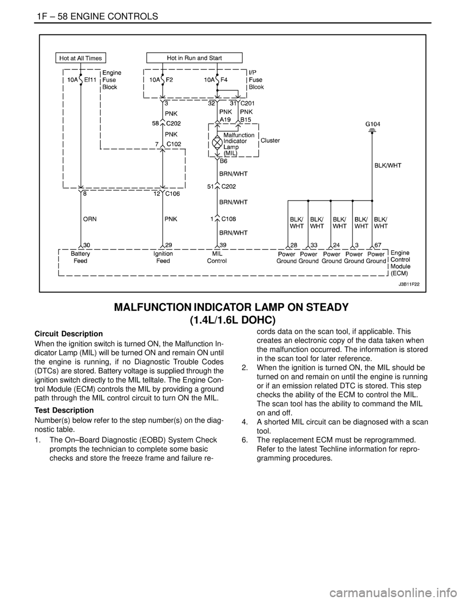
MALFUNCTION INDICATOR LAMP ON STEADY
(1.4L/1.6L DOHC)
Circuit Description
When the ignition switch is turned ON, the Malfunction In-
dicator Lamp (MIL) will be turned ON and remain ON until
the engine is running, if no Diagnostic Trouble Codes
(DTCs) are stored. Battery voltage is supplied through the
ignition switch directly to the MIL telltale. The Engine Con-
trol Module (ECM) controls the MIL by providing a ground
path through the MIL control circuit to turn ON the MIL.
Test Description
Number(s) below refer to the step number(s) on the diag-
nostic table.
1. The On–Board Diagnostic (EOBD) System Check
prompts the technician to complete some basic
checks and store the freeze frame and failure re-cords data on the scan tool, if applicable. This
creates an electronic copy of the data taken when
the malfunction occurred. The information is stored
in the scan tool for later reference.
2. When the ignition is turned ON, the MIL should be
turned on and remain on until the engine is running
or if an emission related DTC is stored. This step
checks the ability of the ECM to control the MIL.
The scan tool has the ability to command the MIL
on and off.
4. A shorted MIL circuit can be diagnosed with a scan
tool.
6. The replacement ECM must be reprogrammed.
Refer to the latest Techline information for repro-
gramming procedures.
Page 306 of 2643

1F – 60IENGINE CONTROLS
DAEWOO V–121 BL4
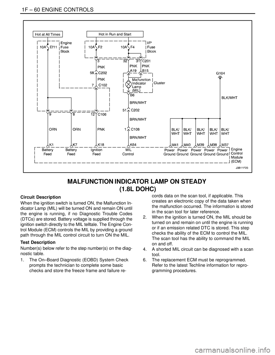
MALFUNCTION INDICATOR LAMP ON STEADY
(1.8L DOHC)
Circuit Description
When the ignition switch is turned ON, the Malfunction In-
dicator Lamp (MIL) will be turned ON and remain ON until
the engine is running, if no Diagnostic Trouble Codes
(DTCs) are stored. Battery voltage is supplied through the
ignition switch directly to the MIL telltale. The Engine Con-
trol Module (ECM) controls the MIL by providing a ground
path through the MIL control circuit to turn ON the MIL.
Test Description
Number(s) below refer to the step number(s) on the diag-
nostic table.
1. The On–Board Diagnostic (EOBD) System Check
prompts the technician to complete some basic
checks and store the freeze frame and failure re-cords data on the scan tool, if applicable. This
creates an electronic copy of the data taken when
the malfunction occurred. The information is stored
in the scan tool for later reference.
2. When the ignition is turned ON, the MIL should be
turned on and remain on until the engine is running
or if an emission related DTC is stored. This step
checks the ability of the ECM to control the MIL.
The scan tool has the ability to command the MIL
on and off.
4. A shorted MIL circuit can be diagnosed with a scan
tool.
6. The replacement ECM must be reprogrammed.
Refer to the latest Techline information for repro-
gramming procedures.
Page 311 of 2643

ENGINE CONTROLS 1F – 65
DAEWOO V–121 BL4
FUEL PUMP RELAY CIRCUIT CHECK (1.4L/1.6L DOHC)
Circuit Description
When the ignition switch is turned ON, the Engine Control
Module (ECM) will supply battery voltage to activate the
fuel pump relay and run the in–tank fuel pump. The fuel
pump will operate as long as the engine is cranking or run-
ning and the ECM is receiving ignition reference pulses.
If there are no reference pulses, the ECM will shut off the
fuel pump within 2 seconds after the ignition switch is
turned ON.
Diagnostic Aids
An intermittent problem may be caused by a poor connec-
tion, rubbed through wire insulation, or a broken wire in-
side the insulation.Test Description
The number(s) below refer to step(s) on the diagnostic
table.
3. This step checks for the ECM providing a ground
for the operation of the fuel pump relay.
7. By confirming that the wiring is OK using Steps 2
through 6, it can be determined that the fuel pump
relay is at fault.
9. After determining that there is no ground being pro-
vided by the ECM to the fuel pump relay, the fault is
either the ECM or the wiring between the ECM and
the fuel pump relay.
Page 312 of 2643

1F – 66IENGINE CONTROLS
DAEWOO V–121 BL4
Fuel Pump Relay Circuit Check (1.4L/1.6L DOHC)
StepActionValue(s)YesNo
11. Turn the ignition OFF for 10 seconds.
2. Turn the ignition ON.
3. Listen for in–tank fuel pump operation.
Does the fuel pump operate for the time specified?2 secSystem OKGo to Step 2
21. Turn the ignition OFF.
2. Disconnect the fuel pump relay.
3. Connect a test light between the fuel pump
relay connector terminal 30 and ground.
Turn the ignition ON. Is the test light on?–Go to Step 3Go to Step 8
31. Turn the ignition OFF.
2. Connect a test light between the fuel pump
relay connector terminal 86 and battery posi-
tive.
3. Turn the ignition ON.
4. With the ignition ON, the test light should light
for the time specified.
Is the test light on?2 secGo to Step 4Go to Step 9
41. Turn the ignition OFF.
2. Connect a test light between the fuel pump
relay connector terminal 30 and ground.
Is the test light on?–Go to Step 5Go to Step 11
5Check for an open or short to ground in the wire be-
tween the fuel pump relay connector terminal 87 and
the fuel pump connector terminal 3.
Is the problem found?–Go to Step 6Go to Step 7
61. Repair the wire between the fuel pump relay
connector terminal 87 and the fuel pump con-
nector terminal 3.
2. Install the fuel pump relay.
3. Turn the ignition OFF for 10 seconds.
4. Turn the ignition ON.
Does the fuel pump operate for the time specified?2 secSystem OK–
71. Replace the fuel pump relay.
2. Turn the ignition OFF for 10 seconds.
3. Turn the ignition ON.
Does the fuel pump operate for the time specified?2 secSystem OK–
8Check for an open wire between the fuel pump relay
connector terminal 30 and the battery.
Is the problem found?–Go to Step 13–
9Check for an open wire between the fuel pump relay
connector terminal 86 to the engine control module
(ECM) connector terminal 6.
Is the problem found.–Go to Step 10Go to Step 12
101. Repair the wire between the fuel pump relay
connector terminal 86 to the ECM connector
terminal 6.
2. Install the fuel pump relay.
3. Turn the ignition OFF for 10 seconds.
4. Turn the ignition ON.
Does the fuel pump operate for the time specified?2 secSystem OK–
Page 313 of 2643
ENGINE CONTROLS 1F – 67
DAEWOO V–121 BL4
StepNo Yes Value(s) Action
111. Replace the fuse F2 or repair the wire between
the fuel pump relay connector terminal 30 and
the battery.
2. Install the fuel pump relay.
3. Turn the ignition OFF for 10 seconds.
4. Turn the ignition ON.
Does the fuel pump operate for the time specified?2 secSystem OK–
121. Turn the ignition OFF.
2. Replace the ECM.
3. Turn the ignition ON.
Does the fuel pump operate for the time specified?2 secSystem OK–
131. Replace the fuse F2 or repair the wire between
the fuel pump relay connector terminal 30 and
the ignition system
2. Install the fuel pump relay.
3. Turn the ignition OFF for 10 seconds.
4. Turn the ignition ON.
Does the fuel pump operate for the time specified?2 secSystem OK–
Page 314 of 2643

1F – 68IENGINE CONTROLS
DAEWOO V–121 BL4
FUEL PUMP RELAY CIRCUIT CHECK (1.8L DOHC)
Circuit Description
When the ignition switch is turned ON, the Engine Control
Module (ECM) will supply battery voltage to activate the
fuel pump relay and run the in–tank fuel pump. The fuel
pump will operate as long as the engine is cranking or run-
ning and the ECM is receiving ignition reference pulses.
If there are no reference pulses, the ECM will shut off the
fuel pump within 2 seconds after the ignition switch is
turned ON.
Diagnostic Aids
An intermittent problem may be caused by a poor connec-
tion, rubbed through wire insulation, or a broken wire in-
side the insulation.Test Description
The number(s) below refer to step(s) on the diagnostic
table.
3. This step checks for the ECM providing a ground
for the operation of the fuel pump relay.
7. By confirming that the wiring is OK using Steps 2
through 6, it can be determined that the fuel pump
relay is at fault.
9. After determining that there is no ground being pro-
vided by the ECM to the fuel pump relay, the fault is
either the ECM or the wiring between the ECM and
the fuel pump relay.