2004 DAEWOO NUBIRA coolant
[x] Cancel search: coolantPage 176 of 2643

1C2 – 56I1.8L DOHC ENGINE MECHANICAL
DAEWOO V–121 BL4
UNIT REPAIR
CYLINDER HEAD AND VALVE TRAIN
COMPONENTS
Tools Required
MKM–571–B Gauge
KM–340–0 Cutter Set
KM–340–7 Guide Drift
KM–340–13 Cutters
KM–340–26 Cutters
KM–348 Valve Spring Compressor
KM–653 Adapter
KM–805 Valve Guide Reamer
Disassembly Procedure
1. Remove the cylinder head with the intake manifold
and the exhaust manifold attached. Refer to ”Cylin-
der Head and Gasket” in this section.
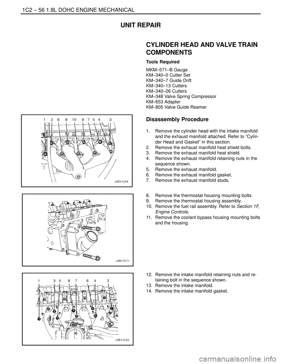
2. Remove the exhaust manifold heat shield bolts.
3. Remove the exhaust manifold heat shield.
4. Remove the exhaust manifold retaining nuts in the
sequence shown.
5. Remove the exhaust manifold.
6. Remove the exhaust manifold gasket.
7. Remove the exhaust manifold studs.
8. Remove the thermostat housing mounting bolts.
9. Remove the thermostat housing assembly.
10. Remove the fuel rail assembly. Refer to Section 1F,
Engine Controls.
11. Remove the coolant bypass housing mounting bolts
and the housing.
12. Remove the intake manifold retaining nuts and re-
taining bolt in the sequence shown.
13. Remove the intake manifold.
14. Remove the intake manifold gasket.
Page 182 of 2643

1C2 – 62I1.8L DOHC ENGINE MECHANICAL
DAEWOO V–121 BL4
14. Install the intake camshaft.
15. Install the intake camshaft bearing caps in their
original positions.
16. Install the exhaust camshaft.
17. Install the exhaust camshaft bearing caps in their
original positions.
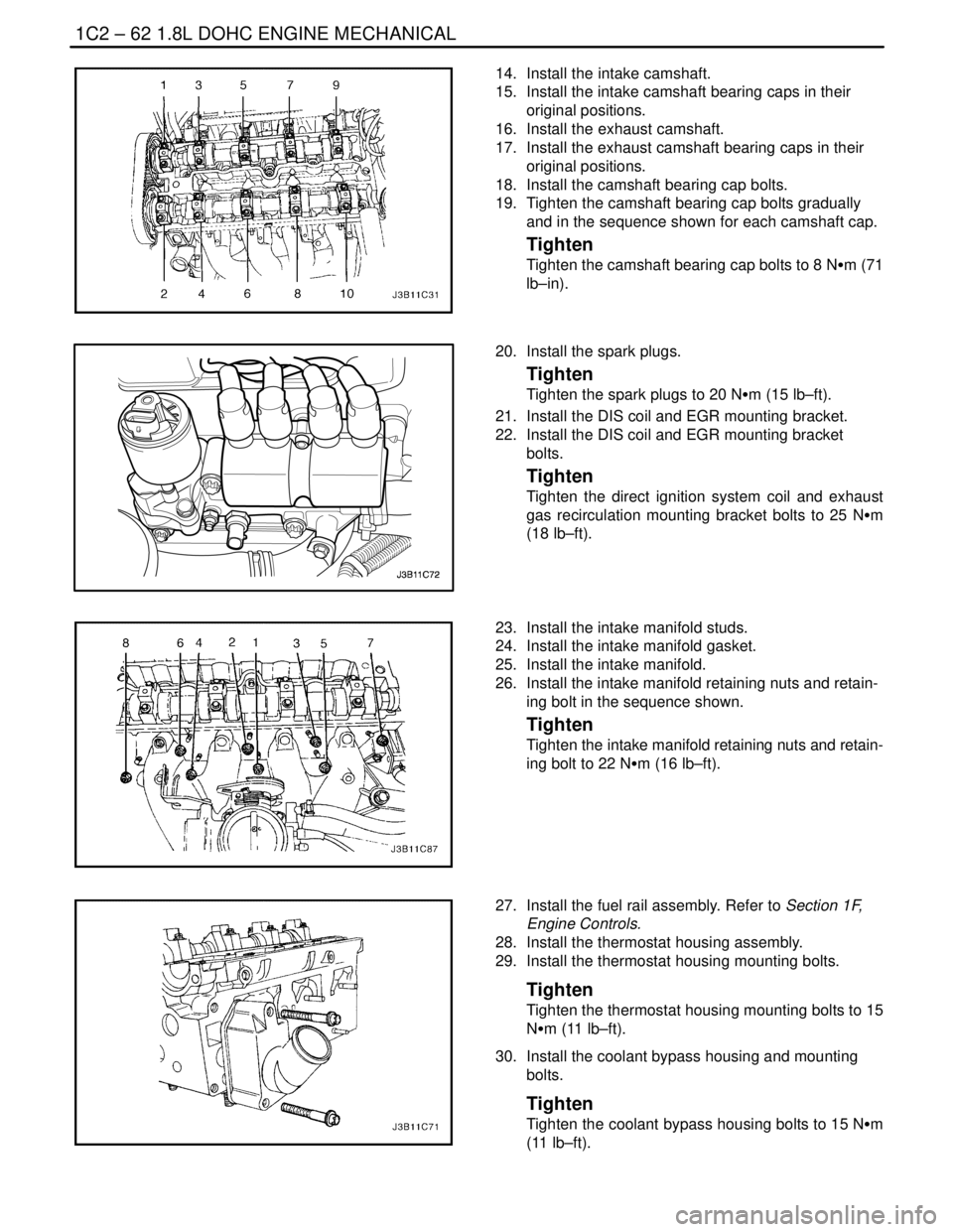
18. Install the camshaft bearing cap bolts.
19. Tighten the camshaft bearing cap bolts gradually
and in the sequence shown for each camshaft cap.
Tighten
Tighten the camshaft bearing cap bolts to 8 NSm (71
lb–in).
20. Install the spark plugs.
Tighten
Tighten the spark plugs to 20 NSm (15 lb–ft).
21. Install the DIS coil and EGR mounting bracket.
22. Install the DIS coil and EGR mounting bracket
bolts.
Tighten
Tighten the direct ignition system coil and exhaust
gas recirculation mounting bracket bolts to 25 NSm
(18 lb–ft).
23. Install the intake manifold studs.
24. Install the intake manifold gasket.
25. Install the intake manifold.
26. Install the intake manifold retaining nuts and retain-
ing bolt in the sequence shown.
Tighten
Tighten the intake manifold retaining nuts and retain-
ing bolt to 22 NSm (16 lb–ft).
27. Install the fuel rail assembly. Refer to Section 1F,
Engine Controls.
28. Install the thermostat housing assembly.
29. Install the thermostat housing mounting bolts.
Tighten
Tighten the thermostat housing mounting bolts to 15
NSm (11 lb–ft).
30. Install the coolant bypass housing and mounting
bolts.
Tighten
Tighten the coolant bypass housing bolts to 15 NSm
(11 lb–ft).
Page 195 of 2643

1.8L DOHC ENGINE MECHANICAL 1C2 – 75
DAEWOO V–121 BL4
GENERAL DESCRIPTION
AND SYSTEM OPERATION
CYLINDER HEAD AND GASKET
The cylinder head is made of an aluminum alloy. The cylin-
der head uses cross–flow intake and exhaust ports. A
spark plug is located in the center of each combustion
chamber. The cylinder head houses the dual camshafts.
CRANKSHAFT
The crankshaft has eight integral weights which are cast
with it for balancing. Oil holes run through the center of the
crankshaft to supply oil to the connecting rods, the bear-
ings, the pistons, and the other components. The end
thrust load is taken by the thrust washers installed at the
center journal.
TIMING BELT
The timing belt coordinates the crankshaft and the dual
overhead camshafts and keeps them synchronized. The
timing belt also turns the coolant pump. The timing belt
and the pulleys are toothed so that there is no slippage be-
tween them. There are two idler pulleys. An automatic ten-
sioner pulley maintains the timing belt’s correct tension.
The timing belt is made of a tough reinforced rubber similar
to that used on the serpentine drive belt. The timing belt
requires no lubrication.
OIL PUMP
The oil pump draws engine oil from the oil pan and feeds
it under pressure to the various parts of the engine. An oil
strainer is mounted before the inlet of the oil pump to re-
move impurities which could clog or damage the oil pump
or other engine components. When the crankshaft ro-
tates, the oil pump driven gear rotates. This causes the
space between the gears to constantly open and narrow,
pulling oil in from the oil pan when the space opens and
pumping the oil out to the engine as it narrows.
At high engine speeds, the oil pump supplies a much high-
er amount of oil than required for lubrication of the engine.
The oil pressure regulator prevents too much oil from en-
tering the engine lubrication passages. During normal oil
supply, a coil spring and valve keep the bypass closed, di-
recting all of the oil pumped to the engine. When the
amount of oil being pumped increases, the pressure be-
comes high enough to overcome the force of the spring.This opens the valve of the oil pressure regulator, allowing
the excess oil to flow through the valve and drain back to
the oil pan.
OIL PAN
The engine oil pan is mounted to the bottom of the cylinder
block. The engine oil pan houses the crankcase and is
made of cast aluminum.
Engine oil is pumped from the oil pan by the oil pump. After
it passes through the oil filter, it is fed through two paths
to lubricate the cylinder block and cylinder head. In one
path, the oil is pumped through oil passages in the crank-
shaft to the connecting rods, then to the pistons and cylin-
ders. It then drains back to the oil pan. In the second path,
the oil is pumped through passages to the camshaft. The
oil passes through the internal passageways in the cam-
shafts to lubricate the valve assemblies before draining
back to the oil pan.
EXHAUST MANIFOLD
A single four–port, rear–takedown manifold is used with
this engine. The manifold is designed to direct escaping
exhaust gases out of the combustion chambers with a
minimum of back pressure. The oxygen sensor is
mounted to the exhaust manifold.
INTAKE MANIFOLD
The intake manifold has four independent long ports and
utilizes an inertial supercharging effect to improve engine
torque at low and moderate speeds.
CAMSHAFTS
This engine is a dual overhead camshaft (DOHC) type,
which means there are two camshafts. One camshaft op-
erates the intake valves, and the other camshaft operates
the exhaust valves. The camshafts sit in journals on the
top of the engine (in the cylinder head) and are held in
place by camshaft caps. The camshaft journals of the cyl-
inder head are drilled for oil passages. Engine oil travels
to the camshafts under pressure where it lubricates each
camshaft journal. The oil returns to the oil pan through
drain holes in the cylinder head. The camshaft lobes are
machined into the solid camshaft to precisely open and
close the intake and the exhaust valves the correct
amount at the correct time. The camshaft lobes are oiled
by splash action from pressurized oil escaping from the
camshaft journals.
Page 197 of 2643

1D – 2IENGINE COOLING
DAEWOO V–121 BL4
SPECIFICATIONS
CAPACITY
ApplicationDescription
Coolant in the Cooling System
(1.4L/1.6L DOHC MPFI System)7.0L (1.85 gal) for automatic transaxle
7.0L (1.85 gal) for manual transaxle
Coolant in the Cooling System
(1.8L DOHC MPFI System)7.1L (1.88 gal) for automatic transaxle
7.1L (1.88 gal) for manual transaxle
FASTENER TIGHTENING SPECIFICATIONS
ApplicationNSmLb–FtLb–In
Water Pump Mounting Bolts (1.4L/1.6L DOHC)10–89
Water Pump Mounting Bolts (1.8L DOHC)2518–
Fan Assembly Mounting Bolts4–35
Fan Motor Nut3.2–28
Fan Motor Retaining Screws4–35
Radiator Retaining Bolts, Upper Left and Upper Right8–71
Surge Tank Attaching Bolt5–44
Thermostat Housing Mounting Bolts (1.6L DOHC)2015–
Thermostat Housing Mounting Bolts (1.8L DOHC)1511–
SPECIAL TOOLS
SPECIAL TOOLS TABLE
KM–471
Adapter
Page 198 of 2643

ENGINE COOLING 1D – 3
DAEWOO V–121 BL4
DIAGNOSIS
THERMOSTAT TEST
1. Remove the thermostat from the vehicle. Refer to
”Thermostat” in this section.
2. Make sure the valve spring is tight when the ther-
mostat is fully closed. If the spring is not tight, re-
place the thermostat.
3. Suspend the thermostat and a thermometer in a
pan of 50/50 mixture of ethylene glycol and water.
Do not let the thermostat or the thermometer rest
on the bottom of the pan because the uneven con-
centration of heat on the bottom could result in in-
accurate temperature measurements.
4. Heat the pan on a burner.
5. Use the thermometer to measure the temperature
of the heated solution.
6. The thermostat should begin to open at 87°C
(189°F) and it should be fully open at 102°C
(216°F). If it does not open at these temperatures,
replace the thermostat.
SURGE TANK CAP TEST
Tools Required
KM–471 Adapter
The surge tank cap maintains proper pressure, protects
the system from high pressure by opening a pressure
valve, and protects the coolant hoses from collapsing be-
cause of a vacuum.1. Wash any sludge from the surge tank cap and the
valve seat of the vacuum pressure valve for the
surge tank cap.
2. Check for any damage or deformity to the vacuum
pressure valve for the surge tank cap. If any dam-
age or deformity is found, replace the cap.
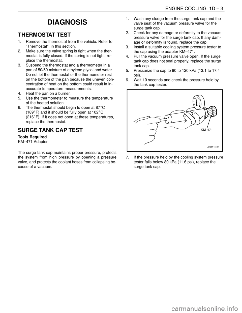
3. Install a suitable cooling system pressure tester to
the cap using the adapter KM–471.
4. Pull the vacuum pressure valve open. If the surge
tank cap does not seal properly, replace the surge
tank cap.
5. Pressurize the cap to 90 to 120 kPa (13.1 to 17.4
psi).
6. Wait 10 seconds and check the pressure held by
the tank cap tester.
7. If the pressure held by the cooling system pressure
tester falls below 80 kPa (11.6 psi), replace the
surge tank cap.
Page 199 of 2643

1D – 4IENGINE COOLING
DAEWOO V–121 BL4
COOLING SYSTEM DIAGNOSIS
Engine Overheats
ChecksAction
Check for a loss of the coolant.Add the coolant.
Check for a weak coolant solution.Confirm that the coolant solution is a 50/50 mixture of eth-
ylene glycol and water.
Check the front of the radiator for any dirt, any leaves, or
any insects.Clean the front of the radiator.
Check for leakage from the hoses, the coolant pump, the
heater, the thermostat housing, the radiator, the core
plugs, or the head gasket.Replace any damaged components.
Check for a faulty thermostat.Replace a damaged thermostat.
Check for retarded ignition timing.Perform an ECM code diagnosis. Confirm the integrity of
the timing belt.
Check for an improperly operating electric cooling fan.Replace the electric cooling fan.
Check for radiator hoses that are plugged or rotted.Replace any damaged radiator hoses.
Check for a faulty water pump.Replace a faulty water pump.
Check for a faulty surge tank cap.Replace a faulty surge tank cap.
Check for a cylinder head or an engine block that is
cracked or plugged.Repair the damaged cylinder head or the damaged engine
block.
Loss of Coolant
ChecksAction
Check for a leak in the radiator.Replace a damaged radiator.
Check for a leak in the following locations:
S Surge tank.
S Hose.Replace the following parts, as needed:
S Surge tank.
S Hose.
Check for loose or damaged radiator hoses, heater hoses,
and connections.Reseat the hoses.
Replace the hoses or the clamps.
Check for leaks in the coolant pump seal.Replace the coolant pump seal.
Check for leaks in the coolant pump gasket.Replace the coolant pump gasket.
Check for an improper cylinder head torque.Tighten the cylinder head bolts to specifications.
Replace the cylinder head gasket, if needed.
Check for leaks in the following locations:
S Intake manifold.
S Cylinder head gasket.
S Cylinder block plug.
S Heater core.
S Radiator drain plug.Repair or replace any components, as needed, to correct
the leak.
Engine Fails to Reach Normal Operating Temperature or Cool Air
from the Heater
ChecksAction
Check to determine if the thermostat is stuck open or is the
wrong type of thermostat.Install a new thermostat of the correct type and heat range.
Check the coolant level to determine if it is below the MIN
mark on the surge tank.Add sufficient coolant to raise the fluid to the specified
mark on the surge tank.
Page 202 of 2643

ENGINE COOLING 1D – 7
DAEWOO V–121 BL4
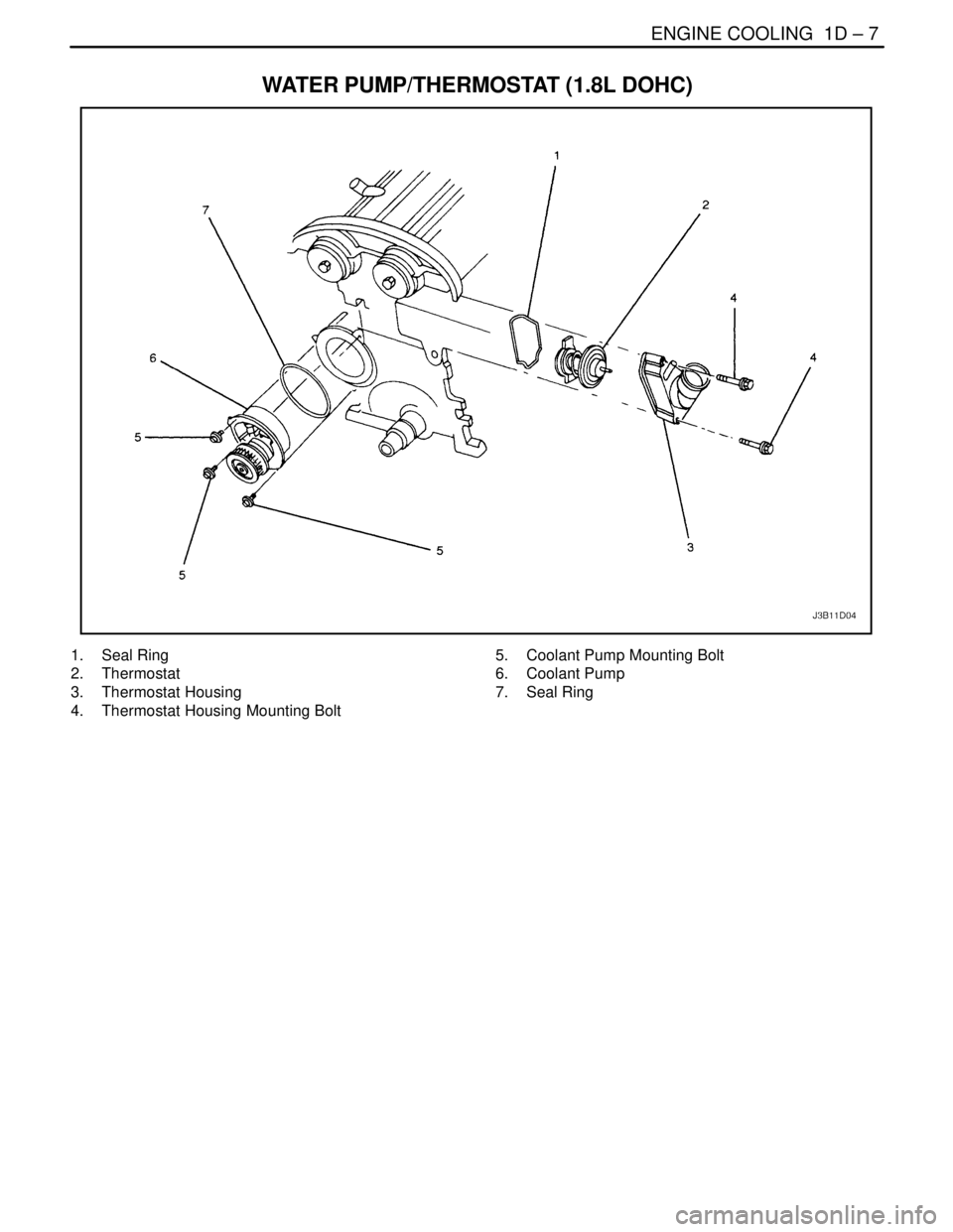
WATER PUMP/THERMOSTAT (1.8L DOHC)
1. Seal Ring
2. Thermostat
3. Thermostat Housing
4. Thermostat Housing Mounting Bolt5. Coolant Pump Mounting Bolt
6. Coolant Pump
7. Seal Ring
Page 203 of 2643

1D – 8IENGINE COOLING
DAEWOO V–121 BL4
MAINTENANCE AND REPAIR
ON–VEHICLE SERVICE
DRAINING AND REFILLING THE
COOLING SYSTEM
CAUTION : Do not remove the surge tank cap while
the engine and the radiator are hot. Scalding fluid and
steam may be blown out under pressure.
1. Place a pan below the vehicle to catch the draining
coolant.
2. Remove the surge tank cap.
3. Unplug the drain cock.
CAUTION : Dispose of the used coolant to a used
coolant holding tank to be picked up with the used oil
for disposal. Never pour the used coolant down the
drain. Ethylene glycol antifreeze is an extremely toxic
chemical. Disposing of it into the sewer system or the
ground water can contaminate the local environment.
4. Catch the escaping fluid in a drain pan.
5. Remove all sludge and dirt from inside the surge
tank. Refer to ”Surge Tank” in this section.
6. Plug the drain cock.
7. Add the clean water to the surge tank.
8. Fill the tank slowly so that the upper reservoir hose
remains above the water line. This allows the air
inside the cooling system to escape.
9. Start the engine.
10. Run the engine until the thermostat opens. You can
tell the thermostat is open when both radiator
hoses are hot to the touch.
11. Stop the engine.
12. Repeat Steps 1 through 9 until the drained water is
clear and free of coolant and rust.
Notice : Never use an antifreeze mixture more concen-
trated than 60 percent antifreeze to 40 percent water. The
solution freezing point increases above this concentration.
13. Fill the cooling system through the surge tank with
a mixture of ethylene glycol antifreeze and water.
The mixture must be at least 50 percent antifreeze,
but not more than 60 percent antifreeze.
14. Fill the surge tank to the specified MAX fill mark on
the outside of the tank.