2004 DAEWOO NUBIRA clutch
[x] Cancel search: clutchPage 833 of 2643

ENGINE CONTROLS 1F – 587
DAEWOO V–121 BL4
POOR FUEL ECONOMY
Definition : Fuel economy, as measured by an actual road
test, is noticeably lower than expected. Also, fuel econo-
my is noticeably lower than it was on this vehicle at one
time, as previously shown by an actual road test.
Important : Driving habits affect fuel economy. Check the
owner’s driving habits by asking the following questions:1. Is the A/C system (i.e. defroster mode) turned on
all the time?
2. Are the tires at the correct air pressure?
3. Have excessively heavy loads been carried?
4. Does the driver accelerate too much and too often?
Suggest the driver read the section in the owner’s
manual about fuel economy.
Step
ActionValue(s)YesNo
1Were the Important Preliminary Checks performed?–Go toStep 2Go to
”Important Pre-
liminary
Checks”
21. Inspect the air filter for excessive contamina-
tion.
2. Inspect for fuel system leaks.
Are all needed checks complete?–Go toStep 3–
31. Inspect the spark plugs for excessive wear,
insulation cracks, improper gap, or heavy de-
posits.
2. Replace any faulty spark plugs.
3. Inspect the ignition wires for cracking, hard-
ness, and proper connections.
Are all needed checks and repairs complete?–Go toStep 4–
41. Inspect the engine coolant level.
2. Check the thermostat for being always open or
for an incorrect heat range.
3. Replace the thermostat as needed.
Are all needed checks and repairs complete?–Go toStep 5–
51. Check the transaxle shift pattern. Ensure all
transaxle gears are functioning.
2. Check the Torque Converter Clutch (TCC) op-
eration with a scan tool. The scan tool should
indicate rpm drop when the TCC is command-
ed on.
3. Check for proper calibration of the speedome-
ter.
4. Check the brakes for dragging.
5. Check the cylinder compression.
6. Repair, replace, or adjust any components as
needed.
Are all checks and needed repairs complete?–System OK–
Page 873 of 2643

ENGINE CONTROLS 1F – 627
DAEWOO V–121 BL4
A closed throttle on engine coast down produces a rela-
tively low MAP output. MAP is the opposite of vacuum.
When manifold pressure is high, vacuum is low. The MAP
sensor is also used to measure barometric pressure. This
is performed as part of MAP sensor calculations. With the
ignition ON and the engine not running, the engine control
module (ECM) will read the manifold pressure as baromet-
ric pressure and adjust the air/fuel ratio accordingly. This
compensation for altitude allows the system to maintaindriving performance while holding emissions low. The
barometric function will update periodically during steady
driving or under a wide open throttle condition. In the case
of a fault in the barometric portion of the MAP sensor, the
ECM will set to the default value.
A failure in the MAP sensor circuit sets a diagnostic trouble
code P0107 or P0108.
The following tables show the difference between absolute pressure and vacuum related to MAP sensor output, which
appears as the top row of both tables.
MAP
Volts4.94.43.83.32.72.21.71.10.60.30.3
kPa1009080706050403020100
in. Hg29.626.623.720.717.714.811.88.95.92.90
VACUUM
Volts4.94.43.83.32.72.21.71.10.60.30.3
kPa0102030405060708090100
in. Hg02.95.98.911.814.817..720.723.726.729.6
ENGINE CONTROL MODULE
The engine control module (ECM), located inside the pas-
senger kick–panel, is the control center of the fuel injection
system. It constantly looks at the information from various
sensors and controls the systems that affect the vehicle’s
performance. The ECM also performs the diagnostic func-
tions of the system. It can recognize operational problems,
alert the driver through the Malfunction Indicator Lamp
(MIL), and store diagnostic trouble code(s) which identify
problem areas to aid the technician in making repairs.
There are no serviceable parts in the ECM. The calibra-
tions are stored in the ECM in the Programmable Read–
Only Memory (PROM).
The ECM supplies either 5 or 12 volts to power the sensors
or switches. This is done through resistances in the ECM
which are so high in value that a test light will not come on
when connected to the circuit. In some cases, even an or-
dinary shop voltmeter will not give an accurate reading be-
cause its resistance is too low. You must use a digital volt-
meter with a 10 megohm input impedance to get accurate
voltage readings. The ECM controls output circuits such
as the fuel injectors, the idle air control valve, the A/C
clutch relay, etc., by controlling the ground circuit through
transistors or a device called a ”quad–driver.”
FUEL INJECTOR
The Multiport Fuel Injection (MFI) assembly is a solenoid–
operated device controlled by the engine control module
(ECM). It meters pressurized fuel to a single engine cylin-
der. The ECM energizes the fuel injector or the solenoid
to a normally closed ball or pintle valve. This allows fuel toflow into the top of the injector, past the ball or pintle valve,
and through a recessed flow director plate at the injector
outlet.
The director plate has six machined holes that control the
fuel flow, generating a conical spray pattern of finely atom-
ized fuel at the injector tip. Fuel from the tip is directed at
the intake valve, causing it to become further atomized
and vaporized before entering the combustion chamber.
A fuel injector which is stuck partially open will cause a loss
of fuel pressure after the engine is shut down. Also, an ex-
tended crank time will be noticed on some engines. Diesel-
ing can also occur because some fuel can be delivered to
the engine after the ignition is turned OFF.
KNOCK SENSOR
The knock sensor detects abnormal knocking in the en-
gine. The sensor is mounted in the engine block near the
cylinders. The sensor produces an AC output voltage
which increases with the severity of the knock. This signal
is sent to the engine control module (ECM). The ECM then
adjusts the ignition timing to reduce the spark knock.
ROUGH ROAD SENSOR
The engine control module (ECM) receives rough road in-
formation from the VR sensor. The ECM uses the rough
road information to enable or disable the misfire diagnos-
tic. The misfire diagnostic can be greatly affected by
crankshaft speed variations caused by driving on rough
road surfaces. The VR sensor generates rough road infor-
mation by producing a signal which is proportional to the
movement of a small metal bar inside the sensor.
If a fault occurs which causes the ECM to not receive
rough road information between 30 and 80 mph (50 and
132 km/h), DTC P1391 will set.
Page 877 of 2643

ENGINE CONTROLS 1F – 631
DAEWOO V–121 BL4
S Barometric Pressure (BARO)
S Intake Air Temperature (IAT)
S Throttle Position (TP)
S High canister purge
S Fuel trim
S A/C on
Trip
Technically, a trip is a key–on run key–off cycle in which all
the enable criteria for a given diagnostic are met, allowing
the diagnostic to run. Unfortunately, this concept is not
quite that simple. A trip is official when all the enable crite-
ria for a given diagnostic are met. But because the enable
criteria vary from one diagnostic to another, the definition
of trip varies as well. Some diagnostics are run when the
vehicle is at operating temperature, some when the ve-
hicle first starts up; some require that the vehicle be cruis-
ing at a steady highway speed, some run only when the
vehicle is at idle; some diagnostics function with the
Torque Converter Clutch (TCC) disabled. Some run only
immediately following a cold engine startup.
A trip then, is defined as a key–on run key–off cycle in
which the vehicle was operated in such a way as to satisfy
the enables criteria for a given diagnostic, and this diag-
nostic will consider this cycle to be one trip. However,
another diagnostic with a different set of enable criteria
(which were not met) during this driving event, would not
consider it a trip. No trip will occur for that particular diag-
nostic until the vehicle is driven in such a way as to meet
all the enable criteria
Diagnostic Information
The diagnostic charts and functional checks are designed
to locate a faulty circuit or component through a process
of logical decisions. The charts are prepared with the re-
quirement that the vehicle functioned correctly at the time
of assembly and that there are not multiple faults present.
There is a continuous self–diagnosis on certain control
functions. This diagnostic capability is complimented by
the diagnostic procedures contained in this manual. The
language of communicating the source of the malfunction
is a system of diagnostic trouble codes. When a malfunc-
tion is detected by the control module, a diagnostic trouble
code is set and the Malfunction Indicator Lamp (MIL) is illu-
minated.
Malfunction Indicator Lamp (MIL)
The Malfunction Indicator Lamp (MIL) is required by On–
Board Diagnostics (EOBD) that it illuminates under a strict
set of guide lines.
Basically, the MIL is turned on when the engine control
module (ECM) detects a DTC that will impact the vehicle
emissions.The MIL is under the control of the Diagnostic Executive.
The MIL will be turned on if an emissions–related diagnos-
tic test indicates a malfunction has occurred. It will stay on
until the system or component passes the same test, for
three consecutive trips, with no emissions related faults.
Extinguishing the MIL
When the MIL is on, the Diagnostic Executive will turn off
the MIL after three consecutive trips that a ”test passed”
has been reported for the diagnostic test that originally
caused the MIL to illuminate. Although the MIL has been
turned off, the DTC will remain in the ECM memory (both
Freeze Frame and Failure Records) until forty (40) warm–
up cycles after no faults have been completed.
If the MIL was set by either a fuel trim or misfire–related
DTC, additional requirements must be met. In addition to
the requirements stated in the previous paragraph, these
requirements are as follows:
S The diagnostic tests that are passed must occur
with 375 rpm of the rpm data stored at the time the
last test failed.
S Plus or minus ten percent of the engine load that
was stored at the time the last test failed. Similar
engine temperature conditions (warmed up or
warming up) as those stored at the time the last
test failed.
Meeting these requirements ensures that the fault which
turned on the MIL has been corrected.
The MIL is on the instrument panel and has the following
functions:
S It informs the driver that a fault that affects vehicle
emission levels has occurred and that the vehicle
should be taken for service as soon as possible.
S As a system check, the MIL will come on with the
key ON and the engine not running. When the en-
gine is started, the MIL will turn OFF.
S When the MIL remains ON while the engine is run-
ning, or when a malfunction is suspected due to a
driveability or emissions problem, an EOBD System
Check must be performed. The procedures for
these checks are given in EOBD System Check.
These checks will expose faults which may not be
detected if other diagnostics are performed first.
Data Link Connector (DLC)
The provision for communicating with the control module
is the Data Link Connector (DLC). The DLC is used to con-
nect to a scan tool. Some common uses of the scan tool
are listed below:
S Identifying stored DTCs.
S Clearing DTCs.
S Performing output control tests.
S Reading serial data.
Page 1036 of 2643

MASTER CYLINDER 4B – 3
DAEWOO V–121 BL4
MAINTENANCE AND REPAIR
ON–VEHICLE SERVICE
MASTER CYLINDER ASSEMBLY
(Left–Hand Drive Shown, Right–Hand Drive
Similar)
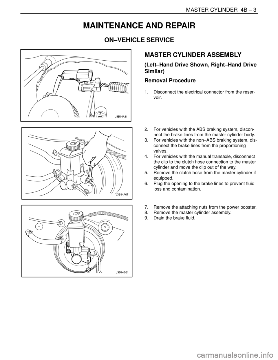
Removal Procedure
1. Disconnect the electrical connector from the reser-
voir.
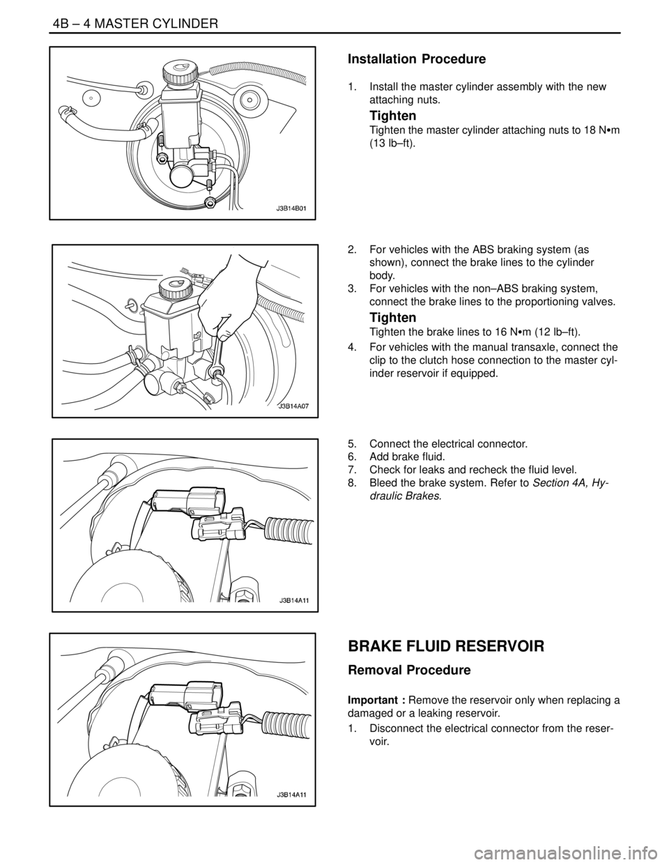
2. For vehicles with the ABS braking system, discon-
nect the brake lines from the master cylinder body.
3. For vehicles with the non–ABS braking system, dis-
connect the brake lines from the proportioning
valves.
4. For vehicles with the manual transaxle, disconnect
the clip to the clutch hose connection to the master
cylinder and move the clip out of the way.
5. Remove the clutch hose from the master cylinder if
equipped.
6. Plug the opening to the brake lines to prevent fluid
loss and contamination.
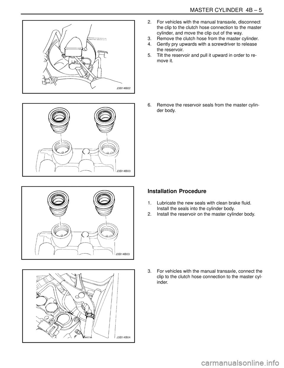
7. Remove the attaching nuts from the power booster.
8. Remove the master cylinder assembly.
9. Drain the brake fluid.
Page 1037 of 2643

4B – 4IMASTER CYLINDER
DAEWOO V–121 BL4
Installation Procedure
1. Install the master cylinder assembly with the new
attaching nuts.
Tighten
Tighten the master cylinder attaching nuts to 18 NSm
(13 lb–ft).
2. For vehicles with the ABS braking system (as
shown), connect the brake lines to the cylinder
body.
3. For vehicles with the non–ABS braking system,
connect the brake lines to the proportioning valves.
Tighten
Tighten the brake lines to 16 NSm (12 lb–ft).
4. For vehicles with the manual transaxle, connect the
clip to the clutch hose connection to the master cyl-
inder reservoir if equipped.
5. Connect the electrical connector.
6. Add brake fluid.
7. Check for leaks and recheck the fluid level.
8. Bleed the brake system. Refer to Section 4A, Hy-
draulic Brakes.
BRAKE FLUID RESERVOIR
Removal Procedure
Important : Remove the reservoir only when replacing a
damaged or a leaking reservoir.
1. Disconnect the electrical connector from the reser-
voir.
Page 1038 of 2643

MASTER CYLINDER 4B – 5
DAEWOO V–121 BL4
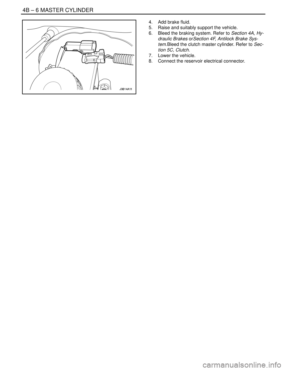
2. For vehicles with the manual transaxle, disconnect
the clip to the clutch hose connection to the master
cylinder, and move the clip out of the way.
3. Remove the clutch hose from the master cylinder.
4. Gently pry upwards with a screwdriver to release
the reservoir.
5. Tilt the reservoir and pull it upward in order to re-
move it.
6. Remove the reservoir seals from the master cylin-
der body.
Installation Procedure
1. Lubricate the new seals with clean brake fluid.
Install the seals into the cylinder body.
2. Install the reservoir on the master cylinder body.
3. For vehicles with the manual transaxle, connect the
clip to the clutch hose connection to the master cyl-
inder.
Page 1039 of 2643

4B – 6IMASTER CYLINDER
DAEWOO V–121 BL4
4. Add brake fluid.
5. Raise and suitably support the vehicle.
6. Bleed the braking system. Refer to Section 4A, Hy-
draulic Brakes orSection 4F, Antilock Brake Sys-
tem.Bleed the clutch master cylinder. Refer to Sec-
tion 5C, Clutch.
7. Lower the vehicle.
8. Connect the reservoir electrical connector.
Page 1350 of 2643

SECTION : 5A1
ZF 4 HP 16 AUTOMATIC TRANSAXLE
CAUTION : Disconnect the negative battery cable before removing or installing any electrical unit or when a tool
or equipment could easily come in contact with exposed electrical terminals. Disconnecting this cable will help
prevent personal injury and damage to the vehicle. The ignition must also be in LOCK unless otherwise noted.
TABLE OF CONTENTS
INTRODUCTION5A1–3 . . . . . . . . . . . . . . . . . . . . . . . . . . .
ZF 4HP 16 Automatic Transaxle 5A1–3. . . . . . . . . . . .
Transaxle Components 5A1–4. . . . . . . . . . . . . . . . . . . .
SPECIFICATIONS5A1–5 . . . . . . . . . . . . . . . . . . . . . . . . .
General Specifications 5A1–5. . . . . . . . . . . . . . . . . . . .
Transaxle Gear Ratio 5A1–5. . . . . . . . . . . . . . . . . . . . . .
Fluid Capacity 5A1–5. . . . . . . . . . . . . . . . . . . . . . . . . . . .
Fastener Tightening Specifications 5A1–5. . . . . . . . . .
Shift Speed Chart 5A1–7. . . . . . . . . . . . . . . . . . . . . . . . .
Line Pressure 5A1–8. . . . . . . . . . . . . . . . . . . . . . . . . . . .
SPECIAL TOOLS5A1–9 . . . . . . . . . . . . . . . . . . . . . . . . . .
Special Tools Table 5A1–9. . . . . . . . . . . . . . . . . . . . . . .
SCHEMATIC AND ROUTING DIAGRAMS5A1–11 . . .
Transaxle Control Module (1 of 2) 5A1–11. . . . . . . . . .
Transaxle Control Module (2 of 2) 5A1–12. . . . . . . . . .
Shift Mode Diagram 5A1–13. . . . . . . . . . . . . . . . . . . . . .
Power Flow Diagram 5A1–17. . . . . . . . . . . . . . . . . . . . .
COMPONENT LOCATOR5A1–33 . . . . . . . . . . . . . . . . . .
Transaxle Identification Information 5A1–33. . . . . . . .
Torque Converter 5A1–34. . . . . . . . . . . . . . . . . . . . . . . .
Transaxle Housing 5A1–35. . . . . . . . . . . . . . . . . . . . . . .
Oil Pump 5A1–36. . . . . . . . . . . . . . . . . . . . . . . . . . . . . . .
Rear Cover & Oil Pan Cover 5A1–37. . . . . . . . . . . . . .
Parking Lever 5A1–38. . . . . . . . . . . . . . . . . . . . . . . . . . .
Input Shaft & Shift Gear 5A1–39. . . . . . . . . . . . . . . . . .
Valve Body 5A1–41. . . . . . . . . . . . . . . . . . . . . . . . . . . . .
Gear Shift Control 5A1–42. . . . . . . . . . . . . . . . . . . . . . .
DIAGNOSTIC INFORMATION AND PROCEDURES
DIAGNOSIS5A1–43 . . . . . . . . . . . . . . . . . . . . . . . . . . . .
Basic Knowledge Required 5A1–43. . . . . . . . . . . . . . . .
Functional Check Procedure 5A1–43. . . . . . . . . . . . . .
Line Pressure Check Procedure 5A1–43. . . . . . . . . . .
Clutch Plate Diagnosis 5A1–45. . . . . . . . . . . . . . . . . . .
Cooler Flushing and Flow Test 5A1–45. . . . . . . . . . . . . Transaxle Fluid Level Service Procedure 5A1–45. . . .
Electrical/Garage Shift Test 5A1–47. . . . . . . . . . . . . . .
Road Test Procedure 5A1–47. . . . . . . . . . . . . . . . . . . . .
Torque Converter Lock–Up Clutch(TCC)
Diagnosis 5A1–48. . . . . . . . . . . . . . . . . . . . . . . . . . . . .
TCM Initialization Procedure 5A1–50. . . . . . . . . . . . . .
Shift Speed Chart 5A1–51. . . . . . . . . . . . . . . . . . . . . . . .
Internal Wiring Harness Check 5A1–51. . . . . . . . . . . .
Transaxle Wiring Harness Connector 5A1–54. . . . . . .
Symptom Diagnosis 5A1–56. . . . . . . . . . . . . . . . . . . . . .
DIAGNOSTIC TROUBLE CODE DIAGNOSIS5A1–60
Diagnostic Trouble Code (DTC) Identification 5A1–60
DTC P0562 – System Voltage Low 5A1–68. . . . . . . . .
DTC P0563 – System Voltage High 5A1–71. . . . . . . .
DTC P0601 – Internal Control Module Memory
Checksum Error 5A1–74. . . . . . . . . . . . . . . . . . . . . . .
DTC P0603 – Internal Control Module Keep
Alive Memory(KAM) Error 5A1–76. . . . . . . . . . . . . . .
DTC P0604 – Internal Control Module Random
Access Memory(RAM) Error 5A1–78. . . . . . . . . . . . .
DTC P0606 – Transaxle Control Module
Processor Fault 5A1–80. . . . . . . . . . . . . . . . . . . . . . . .
DTC P0703 – Brake Switch Circuit
Malfunction 5A1–83. . . . . . . . . . . . . . . . . . . . . . . . . . .
DTC P0705 – Transmission Range Sensor
Circuit Malfunction(PRNDL Input) 5A1–86. . . . . . . .
DTC P0710 – Transmission Fluid Temperature
Sensor Circuit Malfunction 5A1–89. . . . . . . . . . . . . .
DTC P0715 – Input Speed Sensor(ISS) Circuit
Malfunction 5A1–92. . . . . . . . . . . . . . . . . . . . . . . . . . .
DTC P0716 – Input Speed Sensor(ISS) Circuit
Range/Performance 5A1–95. . . . . . . . . . . . . . . . . . . .
DTC P0717 – Input Speed Sensor(ISS) Circuit
No Signal 5A1–98. . . . . . . . . . . . . . . . . . . . . . . . . . . . .
DTC P0720 – Output Speed Sensor(OSS)
Circuit Malfunction 5A1–101. . . . . . . . . . . . . . . . . . . .
DTC P0721 – Output Speed Sensor(OSS)
Circuit Range/Performance 5A1–104. . . . . . . . . . . . .