Page 1920 of 2643

POWER STEERING GEAR 6C – 3
DAEWOO V–121 BL4
DIAGNOSIS
POWER RACK AND PINION STEERING GEAR
Hissing Noise
ChecksAction
Check the intermediate shaft joints for looseness.Tighten the intermediate shaft joints.
Check the power steering hose for contact with other com-
ponents.Be sure the power steering hose is correctly fitted into the
hose clips.
Rattling Noise in Steering Gear
ChecksAction
Check the power steering hose for contact with the body.Be sure the power steering hose is correctly fitted into the
hose clips.
Check the steering gear for insufficient lubrication.Lubricate the steering gear.
Check the steering gear mounting for improper installa-
tion.Tighten the steering gear mounting bracket nuts and bolts.
Check the outer tie rods for improper installation.Tighten the outer tie rod joints. Replace the outer tie rods.
Poor Return of Steering Wheel to Center
ChecksAction
Check the steering wheel for contact with the turn signal
housing.Adjust the turn signal housing.
Check the intermediate shaft joints for binding or loose-
ness.Replace the intermediate shaft.
Check the power steering pump flow control valve for
sticking and improper alignment.Replace the power steering pump.
Check the wheel alignment.Align the wheels.
Check the wheel bearings for wear or damage.Replace the wheel bearings.
Check the intermediate shaft joints for improper installa-
tion.Adjust the intermediate shaft between the steering gear
and the steering column.
Replace the intermediate shaft.
Check the outer tie rods and the ball joints for binding or
looseness.Tighten the tie rods and the ball joints. Replace the tie rods
and the ball joints.
Check the steering gear adjustments.Perform a straight–ahead check.
Check the steering column shaft seal for rubbing on the
shaft.Replace the dash seal.
Check the steering shaft bearings for binding.Replace the stub shaft bearings.
Momentary Increase in Effort When Turning the Wheel Quickly
ChecksAction
Check the power steering pump for internal leaks.Replace the power steering pump.
Check the hoses for damage or restricted flow.Replace the power steering hoses and/or pipes.
Check the power steering fluid level.Fill the power steering fluid reservoir.
Check the power steering pump flow control valve for
sticking and improper operation.Replace the power steering pump.
Page 1922 of 2643

POWER STEERING GEAR 6C – 5
DAEWOO V–121 BL4
POWER RACK AND PINION
STEERING GEAR BENCH TESTING
Removal, Setup and Testing Procedure
Notice : Pressure checks or pressure and flow checks
may also be conducted using this set–up.
1. Disconnect and remove the power steering gear.
Refer to ”Rack and Pinion Assembly” in this sec-
tion.
2. Place the power steering gear on a bench next to
the vehicle.
3. Disconnect the pressure line at the point where the
hose connects to the pipe. Extend this line in order
to reach the power steering gear on the bench.
4. Disconnect the return line from the the power steer-
ing fluid reservoir. Extend this line in order to reach
the power steering gear on the bench.
5. Connect the power steering pipes to the power
steering gear.6. Start the engine and allow it to idle for 10 seconds.
7. Check the power steering fluid level. Refer to Sec-
tion 6A, Power Steering System.
8. Start the engine and turn the rack and pinion stub
shaft to a full turn in each direction. Hold the shaft
against each stop for 5 seconds.
9. Inspect for possible leak points. Refer to Section
6A, Power Steering System.
Installation Procedure
1. Stop the engine.
2. Disconnect the power steering pipes from the pow-
er steering gear.
3. Remove the extensions and reconnect the pressure
and return lines.
4. Install and connect the power steering gear. Refer
to ”Rack and Pinion Assembly” in this section.
5. Start the engine and stay idle for 10 seconds.
6. Check the power steering fluid level. Refer to Sec-
tion 6A, Power Steering System.
Page 1928 of 2643
POWER STEERING GEAR 6C – 11
DAEWOO V–121 BL4
MAINTENANCE AND REPAIR
ON–VEHICLE SERVICE
RACK AND PINION ASSEMBLY
(Left–Hand Drive Shown, Right–Hand Drive
Similar)
Tools Required
KM–507–B Ball Joint Remover
Removal Procedure
1. Disconnect the negative battery cable.
2. Raise and suitably support the vehicle.
3. Remove the wheels. Refer to Section 2E, Tires and
Wheels.
4. Disconnect the power steering gear fluid outlet
pipe. Place a drain pan under the steering gear to
catch the power steering fluid.
5. Disconnect the power steering gear fluid inlet pipe.
6. Position the steering gear straight ahead by turning
the steering wheel until the steering wheel spokes
are vertical and pointed to the left.
7. Scribe a mark on the stub shaft housing that lines
up with a mark on the intermediate shaft lower cou-
pling.
8. Remove the intermediate shaft pinch bolt.
Page 1931 of 2643

6C – 14IPOWER STEERING GEAR
DAEWOO V–121 BL4
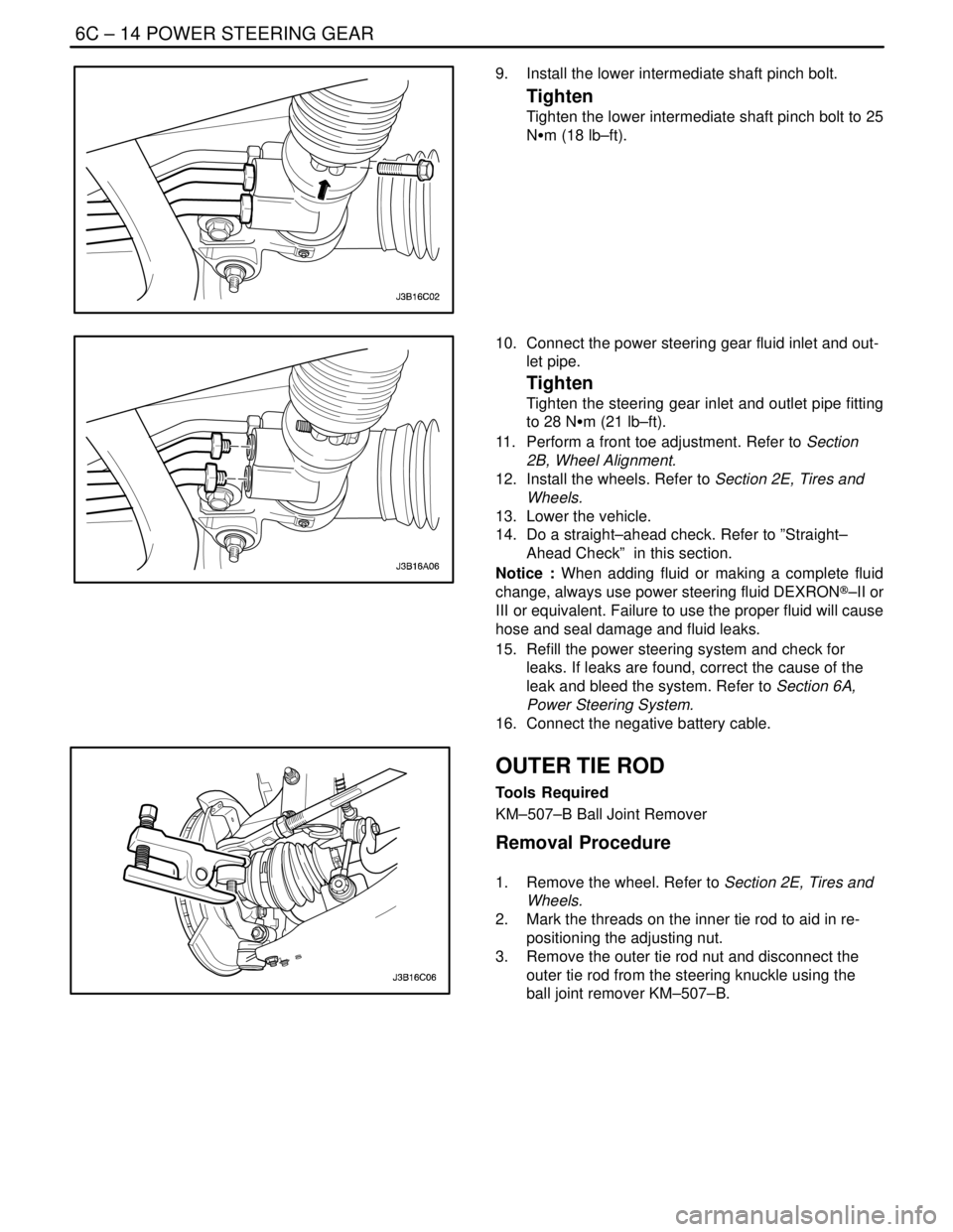
9. Install the lower intermediate shaft pinch bolt.
Tighten
Tighten the lower intermediate shaft pinch bolt to 25
NSm (18 lb–ft).
10. Connect the power steering gear fluid inlet and out-
let pipe.
Tighten
Tighten the steering gear inlet and outlet pipe fitting
to 28 NSm (21 lb–ft).
11. Perform a front toe adjustment. Refer to Section
2B, Wheel Alignment.
12. Install the wheels. Refer to Section 2E, Tires and
Wheels.
13. Lower the vehicle.
14. Do a straight–ahead check. Refer to ”Straight–
Ahead Check” in this section.
Notice : When adding fluid or making a complete fluid
change, always use power steering fluid DEXRON®–II or
III or equivalent. Failure to use the proper fluid will cause
hose and seal damage and fluid leaks.
15. Refill the power steering system and check for
leaks. If leaks are found, correct the cause of the
leak and bleed the system. Refer to Section 6A,
Power Steering System.
16. Connect the negative battery cable.
OUTER TIE ROD
Tools Required
KM–507–B Ball Joint Remover
Removal Procedure
1. Remove the wheel. Refer to Section 2E, Tires and
Wheels.
2. Mark the threads on the inner tie rod to aid in re-
positioning the adjusting nut.
3. Remove the outer tie rod nut and disconnect the
outer tie rod from the steering knuckle using the
ball joint remover KM–507–B.
Page 1937 of 2643

6C – 20IPOWER STEERING GEAR
DAEWOO V–121 BL4
HYDRAULIC CYLINDER LINES
(Left–Hand Drive Shown, Right–Hand
Drive Similar)
Removal Procedure
1. Siphon the power steering fluid from the fluid reser-
voir.
2. Raise and suitably support the vehicle.
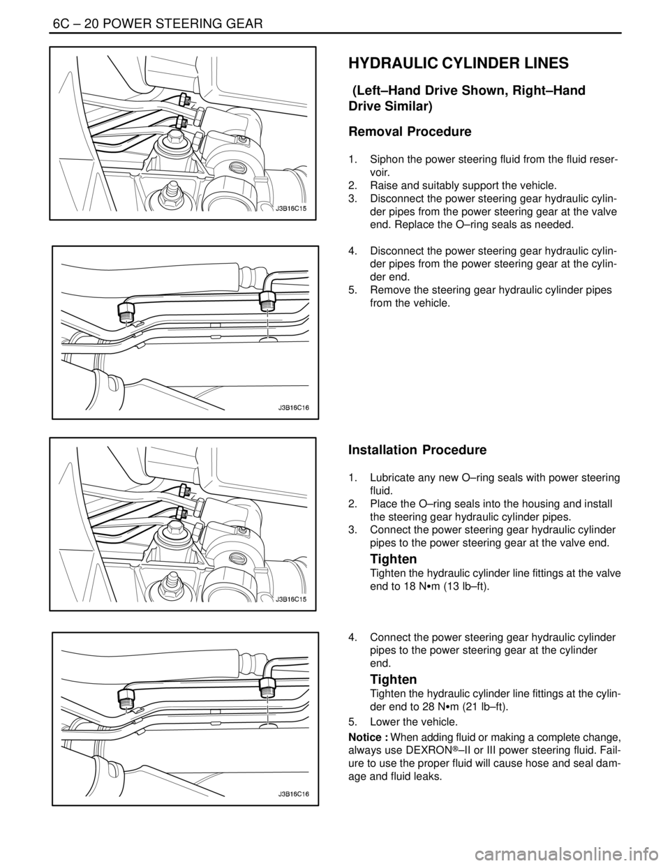
3. Disconnect the power steering gear hydraulic cylin-
der pipes from the power steering gear at the valve
end. Replace the O–ring seals as needed.
4. Disconnect the power steering gear hydraulic cylin-
der pipes from the power steering gear at the cylin-
der end.
5. Remove the steering gear hydraulic cylinder pipes
from the vehicle.
Installation Procedure
1. Lubricate any new O–ring seals with power steering
fluid.
2. Place the O–ring seals into the housing and install
the steering gear hydraulic cylinder pipes.
3. Connect the power steering gear hydraulic cylinder
pipes to the power steering gear at the valve end.
Tighten
Tighten the hydraulic cylinder line fittings at the valve
end to 18 NSm (13 lb–ft).
4. Connect the power steering gear hydraulic cylinder
pipes to the power steering gear at the cylinder
end.
Tighten
Tighten the hydraulic cylinder line fittings at the cylin-
der end to 28 NSm (21 lb–ft).
5. Lower the vehicle.
Notice : When adding fluid or making a complete change,
always use DEXRON®–II or III power steering fluid. Fail-
ure to use the proper fluid will cause hose and seal dam-
age and fluid leaks.
Page 1938 of 2643
POWER STEERING GEAR 6C – 21
DAEWOO V–121 BL4
6. Fill the fluid reservoir with power steering fluid.
7. Inspect for leaks. If there are leaks, correct the
cause of the leaks and bleed the system. Refer to
”Bleeding the Power Steering System” in this sec-
tion.
SPEED SENSITIVE POWER
STEERING CONTROL MODULE
Removal Procedure
1. Disconnect negative battery cable.
2. Remove the glove box. Refer to Section 9G, Interi-
or Trim.
3. Slide the speed sensitive power steering (SSPS)
control module off from the control module bracket.
4. Disconnect the electrical connector from the SSPS
control module.
Installation Procedure
1. Connect the electrical connector to the SSPS con-
trol module.
2. Slide the SSPS control module onto the SSPS con-
trol module bracket.
3. Install the ashtray. Refer to Section 9G, Interior
Trim.
4. Connect the negative battery cable.
Page 1941 of 2643
6C – 24IPOWER STEERING GEAR
DAEWOO V–121 BL4
Assembly Procedure
Notice : Coat all the seals with power steering fluid to en-
sure proper sealing.
1. Install the rack, the bulkhead inner cylinder and the
bulkhead inner cylinder retaining ring.
Notice : To prevent the inner tie rods from loosening, use
Loctite® 242 (or equivalent) on both inner tie rod connec-
tions to secure them to the rack shaft.
Important : The right and left inner tie rods are unequal
in length. Be sure to install the correct inner tie rod on the
proper side of the power steering gear.
2. Firmly seat the inner tie rods against the rack and
tighten both ends simultaneously.
Tighten
Tighten the inner tie rods to 100 NSm (74 lb–ft).
3. Push the plastic retainer back onto the connection
between the inner tie rod and the power steering
gear rack.
4. Install the dust boot.
Page 1944 of 2643
POWER STEERING GEAR 6C – 27
DAEWOO V–121 BL4
6. Remove the stub shaft dust seal the stub shaft
bearing annulus assembly and the valve assembly
from the housing. Discard the stub shaft dust seal.
7. Remove the lower valve assembly bearing and the
bushing.
8. Remove the lower bearing assembly retaining ring
and press the lower bearing assembly from the low-
er end of the housing.
Assembly Procedure
Notice : Coat all the seals with power steering fluid to en-
sure proper sealing.
1. Install the lower bearing assembly and the lower
bearing assembly retaining ring into the lower end
of the housing.