2004 DAEWOO NUBIRA power steering fluid
[x] Cancel search: power steering fluidPage 1948 of 2643

POWER STEERING GEAR 6C – 31
DAEWOO V–121 BL4
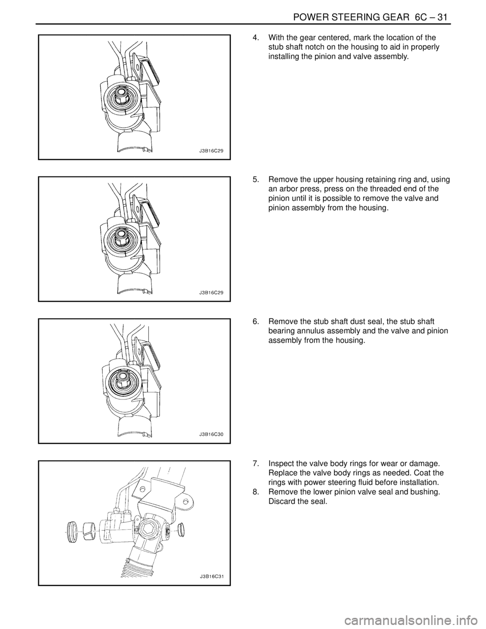
4. With the gear centered, mark the location of the
stub shaft notch on the housing to aid in properly
installing the pinion and valve assembly.
5. Remove the upper housing retaining ring and, using
an arbor press, press on the threaded end of the
pinion until it is possible to remove the valve and
pinion assembly from the housing.
6. Remove the stub shaft dust seal, the stub shaft
bearing annulus assembly and the valve and pinion
assembly from the housing.
7. Inspect the valve body rings for wear or damage.
Replace the valve body rings as needed. Coat the
rings with power steering fluid before installation.
8. Remove the lower pinion valve seal and bushing.
Discard the seal.
Page 1949 of 2643

6C – 32IPOWER STEERING GEAR
DAEWOO V–121 BL4
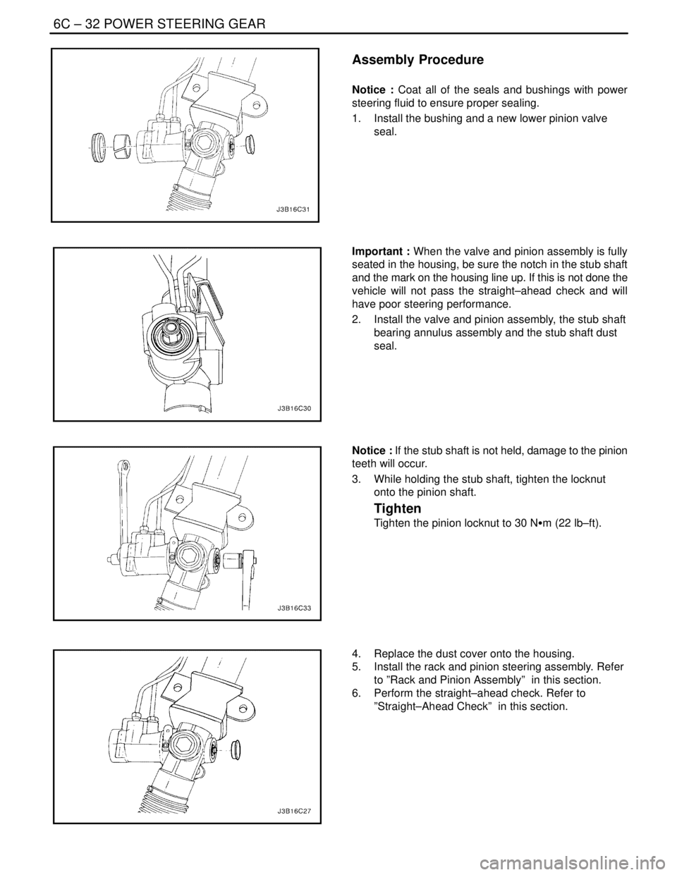
Assembly Procedure
Notice : Coat all of the seals and bushings with power
steering fluid to ensure proper sealing.
1. Install the bushing and a new lower pinion valve
seal.
Important : When the valve and pinion assembly is fully
seated in the housing, be sure the notch in the stub shaft
and the mark on the housing line up. If this is not done the
vehicle will not pass the straight–ahead check and will
have poor steering performance.
2. Install the valve and pinion assembly, the stub shaft
bearing annulus assembly and the stub shaft dust
seal.
Notice : If the stub shaft is not held, damage to the pinion
teeth will occur.
3. While holding the stub shaft, tighten the locknut
onto the pinion shaft.
Tighten
Tighten the pinion locknut to 30 NSm (22 lb–ft).
4. Replace the dust cover onto the housing.
5. Install the rack and pinion steering assembly. Refer
to ”Rack and Pinion Assembly” in this section.
6. Perform the straight–ahead check. Refer to
”Straight–Ahead Check” in this section.
Page 1950 of 2643

POWER STEERING GEAR 6C – 33
DAEWOO V–121 BL4
GENERAL DESCRIPTION
AND SYSTEM OPERATION
POWER RACK AND PINION
The power rack and pinion steering system has a rotary
control valve that directs hydraulic fluid coming from the
hydraulic pump to one side or the other side of the rack pis-
ton. The integral rack piston is attached to the rack. The
rack piston converts hydraulic pressure to a linear force
that moves the rack left or right. That force is then trans-
mitted through the tie rods to the steering knuckles, which
turn the wheels.
If power rack and pinion steering is not available, manual
rack and pinion control is used; however, with this system,
more steering effort is required. The movement of the
steering wheel is transferred to the pinion. The rotary
movement of the pinion is then transferred through the pin-
ion threads, which mesh with teeth on the rack, thereby
causing the rack to move in a linear direction.
A vane–type of hydraulic pump provides hydraulic pres-
sure for both steering systems.
SPEED SENSITIVE POWER
STEERING SYSTEM
The speed sensitive power steering (SSPS) system varies
the driver effort required to steer as the vehicle speed
changes. At low speeds, the system provides maximum
power assist for easy turning and parking maneuvers. At
higher speeds, the steering power is reduced to provide
the driver with firmer steering and directional stability. The
SSPS system accomplishes this by reducing the amount
of power steering fluid flow from the power steering pump
to the power steering gear as the vehicle speed increases.
When the vehicle is stationary, the SSPS system provides
maximum fluid flow to the steering gear. As the vehicle
speed increases, the fluid flow to the steering gear is de-
creased.
Control Module
The SSPS control module processes the vehicle speed in-
formation from the engine control module (ECM) and uses
the steering wheel rotation sensor to provide a control sig-
nal to the electronic variable orifice (EVO) actuator located
on the power steering pump.
Electronic Variable Orifice (EVO) Actuator
The electronic variable orifice (EVO) actuator is located on
the power steering pump and contains a solenoid– oper-
ated pintle valve. Fluid leaving the pump passes through
an orifice in the actuator tip. When the EVO actuator is
powered by the SSPS control module, the pintle moves
into the orifice and reduces the power steering fluid flow.As the vehicle speed increases, current from the SSPS
control module increases, and the pintle blocks more and
more of the orifice.
Steering Wheel Rotation Sensor
The steering wheel rotation sensor is located at the end of
the steering column housing and is used to send a signal
to the controller when abrupt or evasive steering maneu-
vers are needed.
Power Steering Pressure Hose
SSPS vehicles have a specific pressure hose assembly
which includes an in–line check valve in the rack and pin-
ion assembly. This reduces the amount of steering wheel
”kick” when driving over irregular road surfaces while oper-
ating at speeds with reduced flow rate and pressure.
Power Rack and Pinion
Except for differences in valve machining, the design of
the SSPS power rack and pinion assembly is the same as
for the a non–SSPS system. The steering wheel move-
ment is transferred to the pinion via the intermediate shaft.
The pinion moves the rack left or right through meshing the
pinion and the rack teeth. The force is then transmitted
through the tie rods and steering knuckle to steer the
wheels.
The power rack and pinion steering system has a rotary
control valve which directs the hydraulic fluid from the
power steering pump to one side or the other side of the
rack piston. The piston is attached to the rack and uses hy-
draulic pressure to move the rack left or right. The rotary
control valve regulates the degree of assist by responding
to the driver’s torque input.
If hydraulic assist is not available, manual control is main-
tained. However, under this condition, more steering effort
is required.
Power Steering Pump
The standard vane–type pump, which provides hydraulic
pressure for the system, incorporates a special discharge
fitting to hold the EVO actuator.
System Operation
System operation originates with input from the vehicle
speed sensor via the engine control module to the SSPS
control module. The SSPS control module sends a signal
to the SSPS actuator to vary the rate of fluid flow output
by the power steering pump.
Circuit Operation
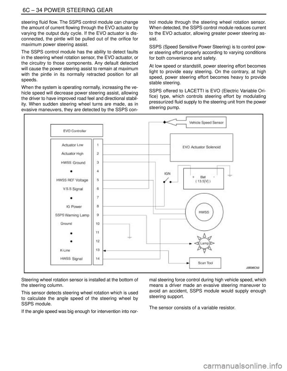
The SSPS system uses inputs from the speed sensor and
steering wheel rotation sensor to the SSPS controller to
determine the desired amount of power steering assist.
The SSPS control module constantly compares the
amount of current flowing through the EVO actuator to the
desired current it has calculated. The EVO actuator has a
pintle that moves in and out of an orifice, regulating power
Page 1951 of 2643

6C – 34IPOWER STEERING GEAR
DAEWOO V–121 BL4
steering fluid flow. The SSPS control module can change
the amount of current flowing through the EVO actuator by
varying the output duty cycle. If the EVO actuator is dis-
connected, the pintle will be pulled out of the orifice for
maximum power steering assist.
The SSPS control module has the ability to detect faults
in the steering wheel rotation sensor, the EVO actuator, or
the circuitry to those components. Any default detected
will cause the power steering assist to remain at maximum
with the pintle in its normally retracted position for all
speeds.
When the system is operating normally, increasing the ve-
hicle speed will decrease power steering assist, allowing
the driver to have improved road feel and directional stabil-
ity. When sudden steering wheel turns are made, as in
evasive maneuvers, they are detected by the SSPS con-trol module through the steering wheel rotation sensor.
When detected, the SSPS control module reduces current
to the EVO actuator, allowing greater power steering as-
sist.
SSPS (Speed Sensitive Power Steering) is to control pow-
er steering effort properly according to varying conditions
for both convenience and safety.
At low speed or standstill, power steering effort becomes
light to provide easy steering. On the contrary, at high
speed, power steering effort becomes heavy to provide
stable steering.
SSPS offered to LACETTI is EVO (Electric Variable Ori-
fice) type, which controls steering effort by modulating
pressurized fluid supply to the steering unit from the power
steering pump.
Steering wheel rotation sensor is installed at the bottom of
the steering column.
This sensor detects steering wheel rotation which is used
to calculate the angle speed of the steering wheel by
SSPS module.
If the angle speed was big enough for intervention into nor-mal steering force control during high vehicle speed, which
means a driver made an evasive steering maneuver to
avoid an accident, SSPS module would supply enough
steering support.
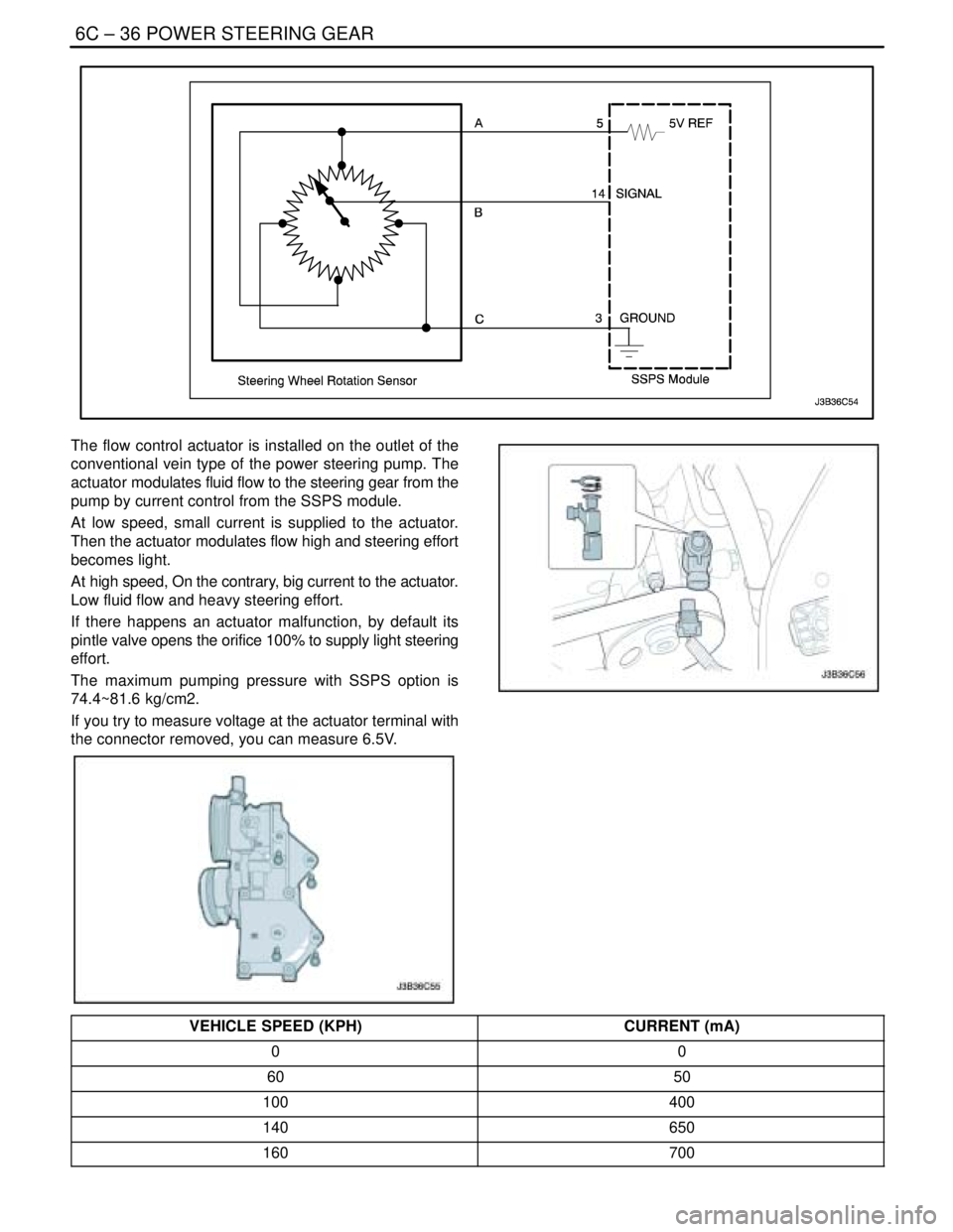
The sensor consists of a variable resistor.
Page 1953 of 2643

6C – 36IPOWER STEERING GEAR
DAEWOO V–121 BL4
The flow control actuator is installed on the outlet of the
conventional vein type of the power steering pump. The
actuator modulates fluid flow to the steering gear from the
pump by current control from the SSPS module.
At low speed, small current is supplied to the actuator.
Then the actuator modulates flow high and steering effort
becomes light.
At high speed, On the contrary, big current to the actuator.
Low fluid flow and heavy steering effort.
If there happens an actuator malfunction, by default its
pintle valve opens the orifice 100% to supply light steering
effort.
The maximum pumping pressure with SSPS option is
74.4~81.6 kg/cm2.
If you try to measure voltage at the actuator terminal with
the connector removed, you can measure 6.5V.
VEHICLE SPEED (KPH)CURRENT (mA)
00
6050
100400
140650
160700
Page 1954 of 2643
![DAEWOO NUBIRA 2004 Service Repair Manual POWER STEERING GEAR 6C – 37
DAEWOO V–121 BL4
[Vehicle Speed – Actuator Current Relation]
SOLENOID RESISTANCE
13 W
The control module is installed on the right side of the au-
dio and can be acc DAEWOO NUBIRA 2004 Service Repair Manual POWER STEERING GEAR 6C – 37
DAEWOO V–121 BL4
[Vehicle Speed – Actuator Current Relation]
SOLENOID RESISTANCE
13 W
The control module is installed on the right side of the au-
dio and can be acc](/manual-img/54/56879/w960_56879-1953.png)
POWER STEERING GEAR 6C – 37
DAEWOO V–121 BL4
[Vehicle Speed – Actuator Current Relation]
SOLENOID RESISTANCE
13 W
The control module is installed on the right side of the au-
dio and can be accessible after the glove box is removed.
It receives signals from the vehicle speed sensor and the
steering wheel rotation sensor and processes them to de-
cide proper fluid flow through the actuator.
It also has a self–diagnosis. If it detects any malfunction,
it starts default mode, which is basically actuator full open
for light steering effort.
TERMINALCOLORFUNCTION
1SBActuator Low
2VActuator High
3BWSteering Wheel Sensor Ground
4–Not used
5GrSteering Wheel Sensor 5V ref.
6GWVSS
7–Not Used
8PIGN ON
9BrWarning Lamp
10BWGround
11–Not Used
12–Not Used
13LDiagnosis
14SBSteering Wheel Sensor Signal
Page 2301 of 2643

9E – 2IINSTRUMENTATION/DRIVER INFORMATION
DAEWOO V–121 BL4
SPECIFICATIONS
FASTENER TIGHTENING SPECIFICATIONS
ApplicationNSmLb–FtLb–In
Air Deflector Screws2–18
Chime Module Screws4–35
Clock Screws2–18
Cupholder Screws2.5–22
Deposit Box Screws2.5–22
Driver Knee Bolster Bolts10–89
Floor Console Brace Bolts4–35
Floor Console Brace Nuts4–35
HVAC Controls Screws4–35
Instrument Cluster Screws4–35
Instrument Cluster Trim Panel Screws4–35
Instrument Panel End Bolts2015–
Instrument Panel End Screws4–35
Instrument Panel Nuts Above the Steering Column2015–
Instrument Panel Bolts Behind the HVAC Controls4–35
Steering Column Bracket Nut2216–
Steering Column Lower Trim Cover Screws2.5–22
Steering Column U–Clamp Nuts2216–
Steering Column Upper Trim Cover Screws3–27
INSTRUMENT CLUSTER INDICATOR LAMPS
SPECIFICATIONS
Indicator LampColorBulb
ABS WarningAmber14 v 1.4 W
Airbag WarningRed14 v 1.4 W
Battery Charge IndicatorRed14 v 1.4 W
Check EngineAmber14 v 1.4 W
Door Open WarningRed14 v 1.4 W
Engine OverheatRed14 v 1.4 W
Fasten Seat Belt WarningRed14 v 1.4 W
High Beam IndicatorBlue14 v 1.4 W
Low Fuel Level WarningAmber14 v 4 W
Oil Pressure WarningRed14 v 1.4 W
Parking Brake Indicator and Brake Fluid WarningRed14 v 1.4 W
Service Engine Soon WarningAmber14 v 1.4 W
Transaxle Power Mode IndicatorAmber14 v 1.4 W
Turn Signal IndicatorsGreen14 v 1.4 W