Page 133 of 2643

1.8L DOHC ENGINE MECHANICAL 1C2 – 13
DAEWOO V–121 BL4
Installation Procedure
1. Apply a small amount of gasket sealant to the cor-
ners of the front camshaft caps and the top of the
rear camshaft cover–to–cylinder head seal.
2. Install the new camshaft cover gasket to the cam-
shaft cover.
3. Install the camshaft cover.
4. Install the camshaft cover bolts.
Tighten
Tighten the camshaft cover bolts to 8 NSm (71 lb–in).
5. Connect the ignition wires to the spark plugs.
6. Install the spark plug cover.
Tighten
Tighten the spark plug cover bolts to 8 NSm (71 lb–in).
7. Install the spark plug cover bolts.
8. Connect the camshaft position sensor connector.
9. Connect all of the necessary vacuum lines.
10. Connect the breather tube to the camshaft cover.
11. Connect the negative battery cable.
CYLINDER HEAD AND GASKET
Tools Required
KM–470–B Angular Torque Gauge
J–28467–B Engine Assembly Support Fixture
Removal Procedure
1. Remove the fuel pump fuse.
2. Start the engine. After it stalls, crank the engine for
10 seconds to rid the fuel system of fuel pressure.
3. Disconnect the negative battery cable.
4. Disconnect the electronic control mdule (ECM)
ground terminal.
5. Drain the engine coolant. Refer to Section 1D, En-
gine Cooling.
Page 136 of 2643
1C2 – 16I1.8L DOHC ENGINE MECHANICAL
DAEWOO V–121 BL4
40. Remove the timing belt idler pulley bolt and nut.
41. Remove the timing belt idler pulleys.
42. Remove the engine mount bolts.
43. Remove the engine mount.
44. Remove the rear timing belt cover bolts.
45. Remove the rear timing belt cover.
46. Remove the exhaust flex pipe retaining nuts at the
exhaust manifold studs.
47. Disconnect all of the necessary vacuum hoses.
48. Disconnect the fuel feed line at the fuel rail.
49. Remove the generator adjusting bracket retaining
bolt and the bracket.
50. Disconnect the coolant hose at the rear cylinder
head and ignition coil exhaust gas recirculation
(EGR) bracket.
51. Disconnect the surge tank coolant hose at the
throttle body.
52. Remove the fuel rail assembly. Refer to Section 1F,
Engine Controls.
Page 138 of 2643

1C2 – 18I1.8L DOHC ENGINE MECHANICAL
DAEWOO V–121 BL4
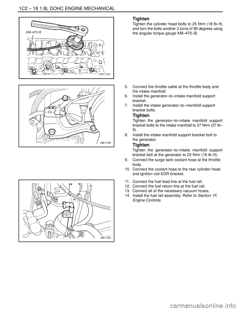
Tighten
Tighten the cylinder head bolts to 25 NSm (18 lb–ft)
and turn the bolts another 3 turns of 90 degrees using
the angular torque gauge KM–470–B.
5. Connect the throttle cable at the throttle body and
the intake manifold.
6. Install the generator–to–intake manifold support
bracket.
7. Install the intake generator–to–manifold support
bracket bolts.
Tighten
Tighten the generator–to–intake manifold support
bracket bolts to the intake manifold to 37 NSm (27 lb–
ft).
8. Install the intake manifold support bracket bolt to
the generator.
Tighten
Tighten the generator–to–intake manifold support
bracket bolt at the generator to 22 NSm (16 lb–ft).
9. Connect the surge tank coolant hose at the throttle
body.
10. Connect the coolant hose to the rear cylinder head
and ignition coil EGR bracket.
11. Connect the fuel feed line at the fuel rail.
12. Connect the fuel return line at the fuel rail.
13. Connect all of the necessary vacuum hoses.
14. Install the fuel rail assembly. Refer to Section 1F,
Engine Controls.
Page 142 of 2643

1C2 – 22I1.8L DOHC ENGINE MECHANICAL
DAEWOO V–121 BL4
56. Connect the CTS connector.
57. Connect the engine CTS connector.
58. Connect the IAC valve connector.
59. Connect the TPS connector.
60. Install the CCP and the EGR solenoid bracket bolt.
Tighten
Tighten the charcoal canister purge and exhaust gas
recirculation solenoid bracket bolt to 5 NSm (44 lb–in).
61. Connect the DIS coil connector.
62. Connect the O2 sensor connector, if equipped.
63. Connect the ECM ground terminal.
64. Install the fuel pump fuse.
65. Connect the negative battery ground cable.
66. Refill the engine cooling system. Refer to Section
1D, Engine Cooling.
CAMSHAFTS
Removal Procedure
1. Remove the timing belt. Refer to ”Timing Belt” in
this section.
2. Disconnect the breather tube at the camshaft cov-
er.
3. Disconnect the engine ventilation hose at the cam-
shaft cover.
4. Remove the spark plug cover bolts.
5. Remove the spark plug cover.
6. Disconnect the ignition wires from the spark plugs.
7. Remove the camshaft cover bolts.
8. Remove the camshaft cover washers.
9. Remove the camshaft cover and the camshaft cov-
er gasket.
Notice : Take extreme care to prevent any scratches,
nicks or damage to the camshafts.
10. While holding the intake camshaft firmly in place,
remove the intake camshaft gear bolt.
11. Remove the intake camshaft gear.
12. While holding the exhaust camshaft firmly in place,
remove the exhaust camshaft gear bolt.
13. Remove the exhaust camshaft gear.
Page 158 of 2643

1C2 – 38I1.8L DOHC ENGINE MECHANICAL
DAEWOO V–121 BL4
3. Install the timing belt idler pulleys.
4. Install the timing belt idler pulley bolt and nut.
Tighten
Tighten the timing belt idler pulley bolt and nut to 25
NSm (18 lb–ft).
5. Tension the timing belt by turning the timing belt
automatic tensioner hex–key tab counterclockwise
until the pointer is aligned to the indicator.
Tighten
Tighten the timing belt automatic tensioner bolt to 25
NSm (18 lb–ft).
6. Install the front timing belt cover.
7. Install the front timing belt cover bolts.
Tighten
Tighten the front timing belt cover bolts to 6 NSm (53
lb–in).
8. Install the engine mount bracket and retaining bolts.
Tighten
Tighten the engine mount bracket retaining bolts to 55
NSm (41 lb–ft).
9. Remove the engine assembly support fixture
J–28467–B, and the channel X–28467–560.
10. Install the serpentine accessory drive belt. Refer to
Section 6B, Power Steering Pump.
11. Connect the negative battery cable.
INTAKE MANIFOLD
Removal Procedure
1. Remove the fuel pump fuse.
2. Start the engine. After it stalls, crank the engine for
10 seconds to rid the fuel system of fuel pressure.
3. Disconnect the negative battery cable.
4. Disconnect the charcoal canister purge (CCP) and
exhaust gas recirculation (EGR) solenoid from the
intake manifold and loosen the bracket bolt.
5. Drain the engine coolant. Refer to Section 1D, En-
gine Cooling.
6. Disconnect the manifold air temperature sensor
(MAT) connector.
7. Disconnect the air cleaner outlet hose from the
throttle body.
Page 159 of 2643

1.8L DOHC ENGINE MECHANICAL 1C2 – 39
DAEWOO V–121 BL4
8. Disconnect the idle air control (IAC) valve connec-
tor.
9. Disconnect the throttle position sensor (TPS) con-
nector.
10. Disconnect the manifold absolute pressure (MAP)
sensor connector.
11. Disconnect the coolant hoses at the throttle body.
12. Disconnect all of the necessary vacuum hoses, in-
cluding the vacuum hose at the fuel pressure regu-
lator and the brake booster vacuum hose at the
intake manifold.
13. Disconnect the throttle cable from the throttle body
and the intake manifold.
14. Remove the throttle cable bracket bolts from the
intake manifold.
15. Remove the throttle cable bracket.
16. Remove the generator–to–intake manifold strap
bracket bolts and strap.
17. Remove the fuel rail as an assembly. Refer to Sec-
tion 1F, Engine Controls.
18. Remove the generator–to–intake manifold support
bracket bolts.
19. Remove the generator–to–intake manifold support
bracket.
20. Remove the intake manifold support bracket bolt at
the engine block and the intake manifold.
21. Remove the intake manifold support bracket.
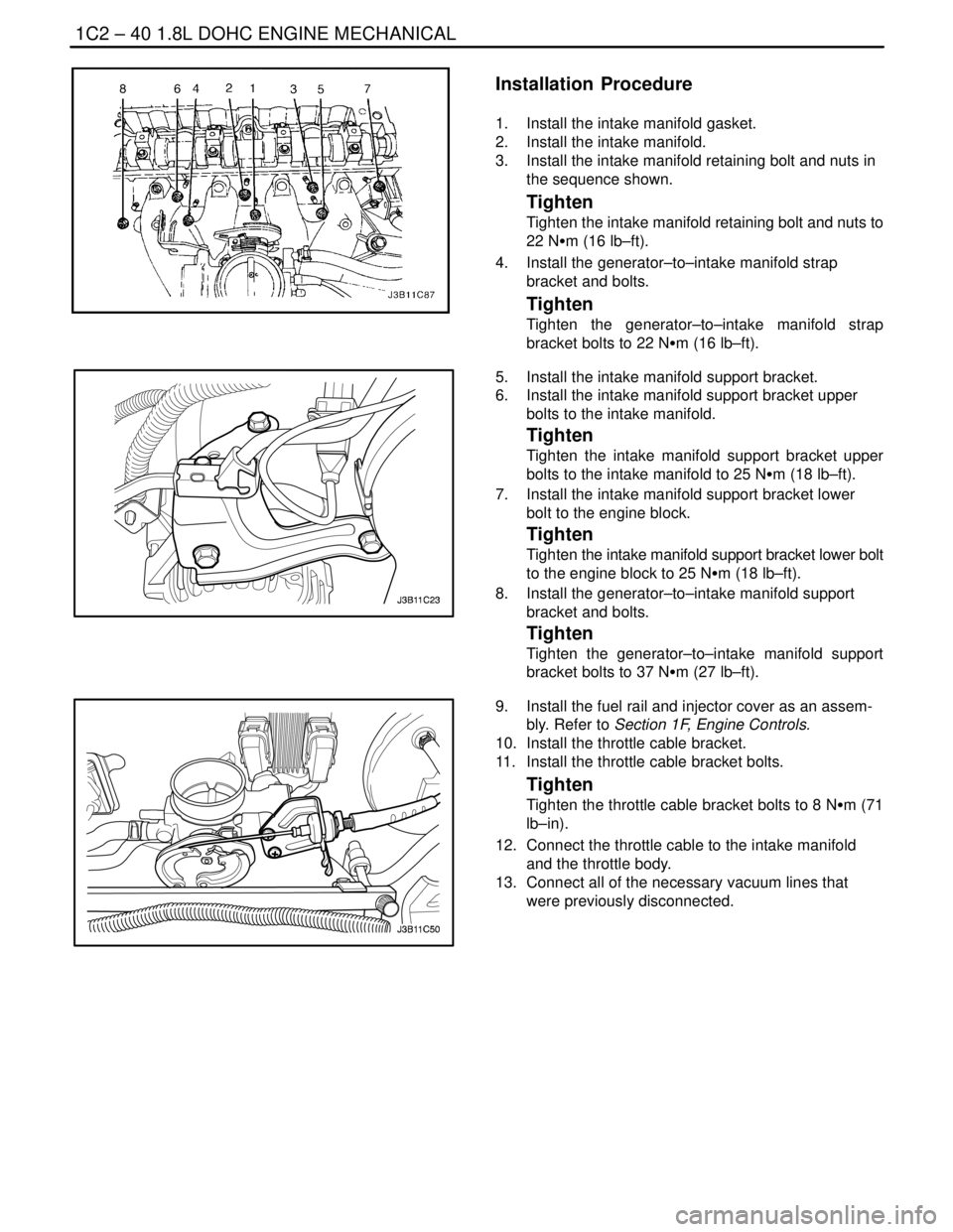
22. Remove the intake manifold retaining bolt and nuts
in the sequence shown.
23. Remove the intake manifold.
24. Remove the intake manifold gasket.
25. Clean the sealing surfaces of the intake manifold
and the cylinder head.
Page 160 of 2643

1C2 – 40I1.8L DOHC ENGINE MECHANICAL
DAEWOO V–121 BL4
Installation Procedure
1. Install the intake manifold gasket.
2. Install the intake manifold.
3. Install the intake manifold retaining bolt and nuts in
the sequence shown.
Tighten
Tighten the intake manifold retaining bolt and nuts to
22 NSm (16 lb–ft).
4. Install the generator–to–intake manifold strap
bracket and bolts.
Tighten
Tighten the generator–to–intake manifold strap
bracket bolts to 22 NSm (16 lb–ft).
5. Install the intake manifold support bracket.
6. Install the intake manifold support bracket upper
bolts to the intake manifold.
Tighten
Tighten the intake manifold support bracket upper
bolts to the intake manifold to 25 NSm (18 lb–ft).
7. Install the intake manifold support bracket lower
bolt to the engine block.
Tighten
Tighten the intake manifold support bracket lower bolt
to the engine block to 25 NSm (18 lb–ft).
8. Install the generator–to–intake manifold support
bracket and bolts.
Tighten
Tighten the generator–to–intake manifold support
bracket bolts to 37 NSm (27 lb–ft).
9. Install the fuel rail and injector cover as an assem-
bly. Refer to Section 1F, Engine Controls.
10. Install the throttle cable bracket.
11. Install the throttle cable bracket bolts.
Tighten
Tighten the throttle cable bracket bolts to 8 NSm (71
lb–in).
12. Connect the throttle cable to the intake manifold
and the throttle body.
13. Connect all of the necessary vacuum lines that
were previously disconnected.
Page 161 of 2643
1.8L DOHC ENGINE MECHANICAL 1C2 – 41
DAEWOO V–121 BL4
14. Connect the MAP sensor connector.
15. Connect the coolant hoses to the throttle body.
16. Connect the IAC valve connector.
17. Connect the TPS connector.
18. Connect the air cleaner outlet hose to the throttle
body.
19. Connect the MAT sensor connector.
20. Connect the CCP and EGR solenoid at the intake
manifold and tighten the bracket bolt.
Tighten
Tighten the charcoal canister purge and exhaust gas
recirculation solenoid bracket bolt to 5 NSm (44 lb–in).
21. Install the fuel pump fuse.
22. Connect the negative battery cable.
23. Refill the engine cooling system. Refer to Section
1D, Engine Cooling.
EXHAUST MANIFOLD
Removal Procedure
1. Disconnect the negative battery cable.
2. Disconnect the oxygen (O2) sensor connector, if
equipped.
3. Remove the exhaust manifold heat shield bolts.
4. Remove the exhaust manifold heat shield.
5. Remove the exhaust flex pipe retaining nuts from
the exhaust manifold studs.