2004 DAEWOO NUBIRA fuel
[x] Cancel search: fuelPage 2496 of 2643
9T2 – 6IIMMOBILIZER ANTI–THEFT SYSTEM
DAEWOO V–121 BL4
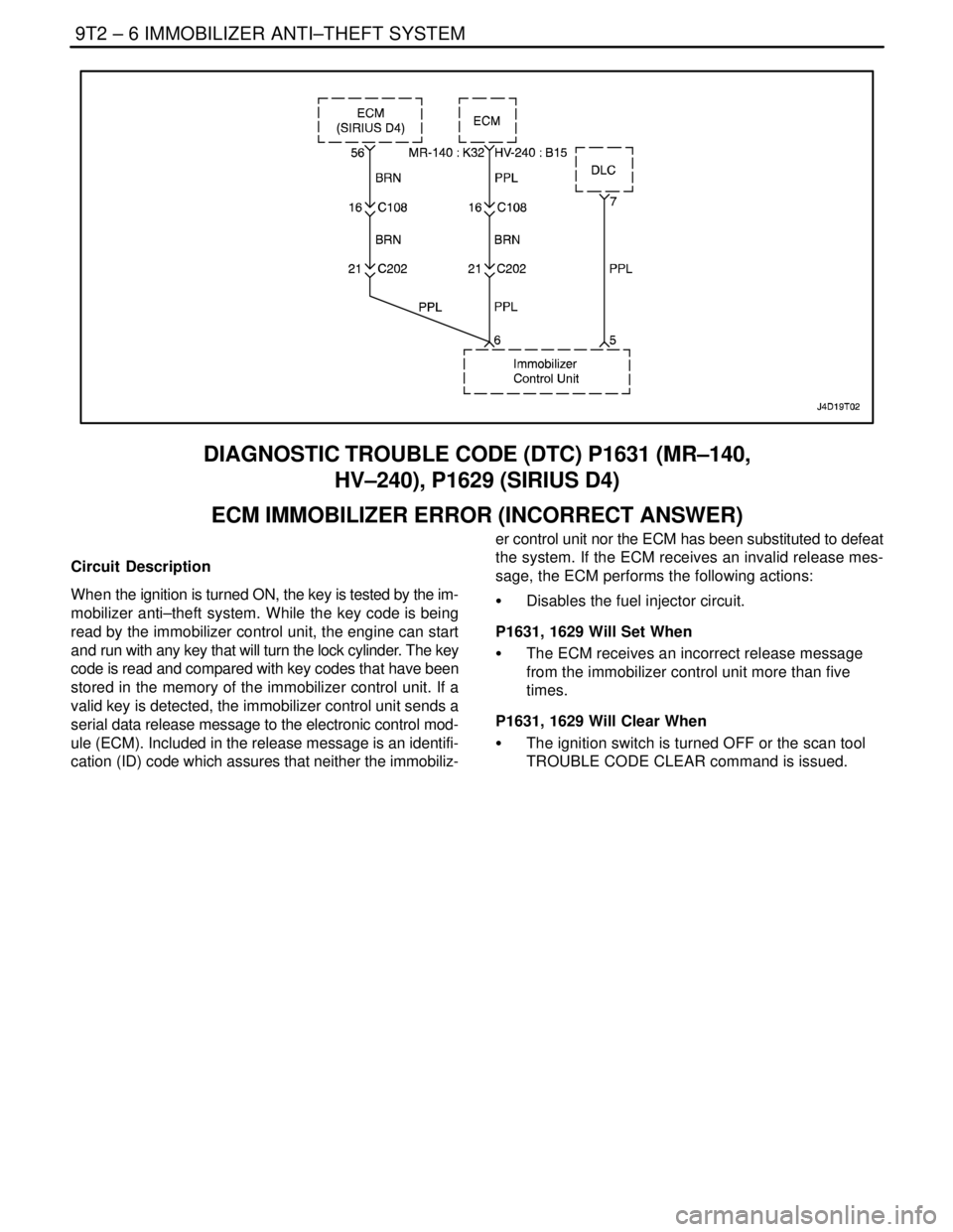
DIAGNOSTIC TROUBLE CODE (DTC) P1631 (MR–140,
HV–240), P1629 (SIRIUS D4)
ECM IMMOBILIZER ERROR (INCORRECT ANSWER)
Circuit Description
When the ignition is turned ON, the key is tested by the im-
mobilizer anti–theft system. While the key code is being
read by the immobilizer control unit, the engine can start
and run with any key that will turn the lock cylinder. The key
code is read and compared with key codes that have been
stored in the memory of the immobilizer control unit. If a
valid key is detected, the immobilizer control unit sends a
serial data release message to the electronic control mod-
ule (ECM). Included in the release message is an identifi-
cation (ID) code which assures that neither the immobiliz-er control unit nor the ECM has been substituted to defeat
the system. If the ECM receives an invalid release mes-
sage, the ECM performs the following actions:
S Disables the fuel injector circuit.
P1631, 1629 Will Set When
S The ECM receives an incorrect release message
from the immobilizer control unit more than five
times.
P1631, 1629 Will Clear When
S The ignition switch is turned OFF or the scan tool
TROUBLE CODE CLEAR command is issued.
Page 2501 of 2643
IMMOBILIZER ANTI–THEFT SYSTEM 9T2 – 11
DAEWOO V–121 BL4
GENERAL DESCRIPTION
AND SYSTEM OPERATION
IMMOBILIZER SYSTEM
The purpose of the Immobilizer system is to provide addi-
tional theft deterrence to the vehicle in which it is installed
and to prevent it from being stolen or driven by unautho-
rized users.
The verification of the user authorization is done by an igni-
tion key with integrated transponder.
The external LED displays the Immobilizer status and has
an additional theft deterrence function.
To secure the communication, the status is exchanged be-
tween the Immobilizer and the ECM in a 5 byte of encoded
data.
These 5 bytes are composed by a mixture of random data
and two types of fixed code
S a vehicle model identification number : MIN
S a vehicle specific identification : VIN
The MIN is known from the first supply of the system.
The VIN is realized by ICU on the special order from the
key coding (reading of transponder code and storing it as
valid key code in Immobilizer EEPROM).
A different random data is computed at each key transi-
tion.
All the immobilization communication between the ECM
and ICU is made on K–line (K line : Serial data line ’7’).
Due to the learning of the Vehicle specific identification
Number, both ICU and ECM can stay in 3 stable modes
S Virgin mode (VIN not learnt)
S Learnt mode (VIN learnt)
S Neutral mode (for a new VIN learning)
In case of using valid key, the release message commu-
nication with the ECM take place and the LED displays the
Immobilizer status valid key In case of using invalid key,
the ECM disables the fuel injector circuit with coded inter-
vention and sets DTC(Diagnostic Trouble Code)
The above conditions are maintained until the ignition is
switched off.
An ECM without an immobilizer control unit cannot be in-
terchanged for an ECM that is used with an immobilizer
control unit system. The Immobilizer control unit and ECM
must have a matching ID code. ID coding and key coding
are accomplished by using Scanner–100
The Immobilizer system consists of
S a maximum or 5 ignition keys with integrated trans-
ponder
S the toroidal coil (Detection coil) for energizing and
reading the transponder mounted at the ignition
lock.S the Immobilizer control unit(ICU) with :
– power supply
– ignition input circuit
– transponder modulation and demodulation unit
– EEPROM
– driver electronic for the external status LED
– serial data link hardware
S the external status LED for displaying the Immobi-
lizer status
S the serial data link between Immobilizer and ECM
ELECTRONICALLY CODED KEYS
Each valid ignition key has an internal transponder which
is a read /write transponder.
The transponder contains an implementation of a crypto–
algorithm with 96 bits of user configurable s cret–key con-
tained in EEPROM and transmits data to the ICU by mod-
ulating the amplitude of the ele tromagnetic field, and
receives data and commands in a similar way.
DETECTION COIL
The toroidal coil is mounted at the ignition lock in front of
the key barrel.
It is connected to the ICU with a four terminal connector
fixed at the body of the coil.
The length of the connection between coil and Immobilizer
is restricted to 50cm. The correct placement on the ignition
lock and the exact electrical data is very important for the
reading distance of transponder.
he toroidal coil and receiving coil inside the transponder
built a transformer. During the readingprocess the coil in-
duces energy into the transponder. The transponder
charges the field and generates an amplitude modulated
signal with the manchester coded data. This charge of the
field is demodulated inside the Immobilizer.
The Immobilizer contains the coil driver hardware for di-
rect connection of the toroidal coil.
IMMOBILIZER CONTROL UNIT
The function of the Immobilizer System is shared between
the ICU and the ECM.
The task of the Immobilizer Electronic Control unit (ICU)
are:
S Reading of the input information ”ignition ON/OFF”
S Controlling the states LED
S Controlling the transponder read/write process
(modulation, demodulation, decoding, comparison
of the read code with the code of the valid keys).
S Communication with the ECM after ignition ON (re-
ceiving of the ECM–request and transmission of
release message).
S Special functions for calculation and handling of the
VIN–code.
The VIN code is calculated by the Immobilizer using a ran-
dom generator.
Page 2510 of 2643
1–2 GENERAL INFORMATIONNUBIRA/LACETTI
1. GENERAL INSTRUCTION
This publication is designed to help you the body repair
technician with your specialized work. Vehicle bodywork
has changed a great deal over the years. As vehicles
have developed technically, vehicle bodywork has also
had to meet new requirements with design, changes to
reconcile apparently conflicting demands to name just a
few examples:
S strength and safety ; low weight
S spaciousness ; good aerodynamices
S high quality ; low price
.
The durability and ease of repair of the bodywork also
plays an important part.
.
Nowadays, the use of highly automated production
equipment makes it possible to maintain the tightest
tolerances and thus ensure a high level of quality.
.
When bodywork is damaged, the customer rightly ex-
pects it to be expertly repaired to the same quality stan-
dards.
.
At the same time, for his safety, the customer expects
you to have comprehensive knowledge of materials,
measuring and straightening methods, possible distor-
tion, optimum corrosion prevention and much more be-
sides.
.
This publication is designed to help you update your
knowledge and give you an idea of what you require to
rectify moderate or severe accident damage, for your
own safety and for the satisfaction of your customers.
2. IMPORTANT SAFETY NOTICE
2–1. BEFORE BEGINNING WORK
S Disconnect the battery to reduce the possibility of fire
caused by electrical shorts.
S Check for fuel leaks and repair as necessary.
S Remove the fuel tank and/or fuel lines if welding equip-
ment is to be used near the fuel system.
S Before welding, sanding or cutting, protect carpets and
seats with fire–proof covers.
S Follow standard safety practices when using toxic or
flammable liquids.
S Use standard safety equipment when spraying paint,
welding, cutting, sanding or grinding. Standard safety
equipment includes.
S Respirator and filter masks: Designed to filter out toxic
fumes, mist, dust or other airborn particles. Use a respi-
rator or filter mask designed to protect you from the haz-
ards of the particular job; some respirators, for example,
are designed to filter out only dust and airborn particles,
not toxic fumes.
S Safety goggles or glasses: Designed to protect your
eyes from projectiles, dust particles or splashing liquid.
S Gloves: Rubber gloves protect against corrosive chemi-
cals. Welding gloves protect against burns and abra-
sions caused by welding, sanding or grinding.
S Safety shoes: Non–slip soles protect against slipping.
Metal toe inserts protect against falling objects.
S Ear plugs: Protect eardrums from harmful noise levels.
.
2–2. DURING WORK
S Do not smoke while working near the fuel system.
S Deposit gas or solvent–soaked shop towels in an ap-
proved container.
S Brake lining contains asbestos, which can cause cancer.
Do not use an air hose to blow off brake assemblies: use
only an approved vacuum cleaner, and wear an ap-
proved filter mask or respirator.
S Always attach a safety cable when using a hydraulic ram
or a frame straightening table: do not stand in direct line
with the chains used on such equipment.
Page 2524 of 2643

2–4 PREPARATIONS OF BODYWORK NUBIRA/LACETTI
2. CHECKPOINTS
S Accurate Inspection of Damaged Parts(Visual)
.
Seat Belts
Always replace the seat belt if :
1. The belt material is cut, punctured, burned or in any
way damaged.
2. The buckle or retractor does not work properly.
3. They were being worn at the time of a collision(also
check for damage at the seat belt anchor points).
4. Their condition is questionable.
.
Front Section :
1. Is there any bending, splitting, denting or other dam-
age to the suspension and its related parts?
2. Is there any deformation of the front panel or radiator
crossmember? Have any of the connected sections
come apart?
3. Are there any creases or distortion in the front wheel-
house or side frame? Have any of the connected sec-
tions come apart?
4. Is there any bending or twisting of the whole front
area?
5. Is there any deformation like creases, bulges, or dents
in the front pillar, dash panel, floor, etc.?
6. Is there any vertical twisting or misaligned clearance
in the door?
7. Is the windshield seal broken?
8. Is there any deformation in the vicinity of the top part
of the roof panel’s center pillar?
9. Is there any damage inside the automobile(is there
any twisting of the dash panel, or anything irregular with
the clearances or sheet–mounting parts)?
10. Is there any damage to the steering wheel? Is there
any deformation in the column and the column–mounted
parts?
11. Is there any oil or water leakage and damage to the en-
gine, transmission or brakes?
12. Is there any irregular noise in the gear changing opera-
tion, engine and transmission rotation?
13. Are there any traces of contact between the engine
block and the center crossmember ?
14. Is there any damage to brake or fuel lines, or wire har-
nesses?Rear Section :
1. Is there any twisting, bulging or denting of the rear floor
any rear bolsters? Have any of the connected sections
come apart?
2. Is there any irregular bulging or denting in the rear
fender?
3. Is there any distortion in the rear inner panel? Is there
any bending and denting in the vicinity of the rear pillar?
4. Is there any distortion or creasing is the rear wheel-
house and arch sections? Have any of the connected
sections come apart?
5. Is there anything irregular in the rear glass seal clear-
ance?
6. Is there any twisting or misalignment of the clearance
of the trunk lid opening section?
7. Is there any bending, splitting, denting or other dam-
age to the suspension and its related parts?
8. Is there any deformation of the rear floor crossmem-
ber, trunk floor panel and back panel? Have any of the
connected sections come apart?
.
Impact Beam :
Always replace the door assembly if :
1. The external force makes the impact beam of door in-
ner deform.
Always replace impact beam if :
2. The external force makes the impact beam of front
bumper and rear bumper deform.
Page 2563 of 2643
NUBIRA/LACETTI ROOF, BACK PANEL AND REAR FLOOR PANEL 5–11
3–2. REPAIR PROCEDURE
1. Remove the related parts.
S Parts to be removed when removing the back panel.
S Rear seat belt and rear seat.
S Muffler, fuel tank and related parts.
S Chassis parts.
S Other related parts.
CAUTION : Do not smoke while working near the
fuel system. Keep open flame away from the fuel
system. If necessary, remove the fuel tank and off
lines.
2. Roughly pull out and straighten the damaged area.
S Check the damage and roughly pull out and re pair the
related back panel, side panel, wheel house inner, rear
longitudinal and other damaged parts with the frame
straightener before remov ing the extension rear floor
panel, rear floor pane and back panel.
S Attach the car to the frame straightener by tightening the
underbody clamps located at the jack up designated
points on the bottom of the frame door opening.
Note : Measure in reference to the dimensions on the
body repair chart.
3. Cut and pry off the back panel.
S The back panel to be cut and pried off when removing
the back panel.
4. Cut and pry off the rear floor and extension rear floor
panel.
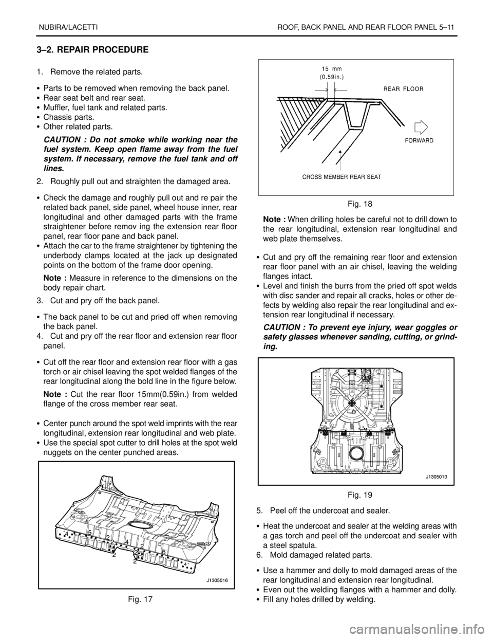
S Cut off the rear floor and extension rear floor with a gas
torch or air chisel leaving the spot welded flanges of the
rear longitudinal along the bold line in the figure below.
Note : Cut the rear floor 15mm(0.59in.) from welded
flange of the cross member rear seat.
S Center punch around the spot weld imprints with the rear
longitudinal, extension rear longitudinal and web plate.
S Use the special spot cutter to drill holes at the spot weld
nuggets on the center punched areas.
Fig. 17
Fig. 18
Note : When drilling holes be careful not to drill down to
the rear longitudinal, extension rear longitudinal and
web plate themselves.
S Cut and pry off the remaining rear floor and extension
rear floor panel with an air chisel, leaving the welding
flanges intact.
S Level and finish the burrs from the pried off spot welds
with disc sander and repair all cracks, holes or other de-
fects by welding also repair the rear longitudinal and ex-
tension rear longitudinal if necessary.
CAUTION : To prevent eye injury, wear goggles or
safety glasses whenever sanding, cutting, or grind-
ing.
Fig. 19
5. Peel off the undercoat and sealer.
S Heat the undercoat and sealer at the welding areas with
a gas torch and peel off the undercoat and sealer with
a steel spatula.
6. Mold damaged related parts.
S Use a hammer and dolly to mold damaged areas of the
rear longitudinal and extension rear longitudinal.
S Even out the welding flanges with a hammer and dolly.
S Fill any holes drilled by welding.
Page 2568 of 2643
NUBIRA/LACETTI FRAME DOOR OPENING, DOOR AND SIDE PANEL OUTER 6–3
1–2. REPAIR PROCEDURE
1. Remove the related parts.
S Doors.
S Weather strips, pillar trims and related parts.
S Carpet.
S Seat belt assembly
S Door switch and wiring harness.
S Fuel pipe and brake oil pipe.
S Other related parts.
Note : Pull out and straighten the damaged area to
approximately the original shape.
2. Remove the related parts.
S Damage may extend to the inner roof frame, the inner
frame door opening and the floor. Determine the extent
of the damage first, so the frame can be pulled out prop-
erly.
Note : Use heat–resistant protective cover for protect
painting areas, seats, carpets and other parts.
S Pull out and straighten the damaged areas.
S Do not pull out more than necessary.
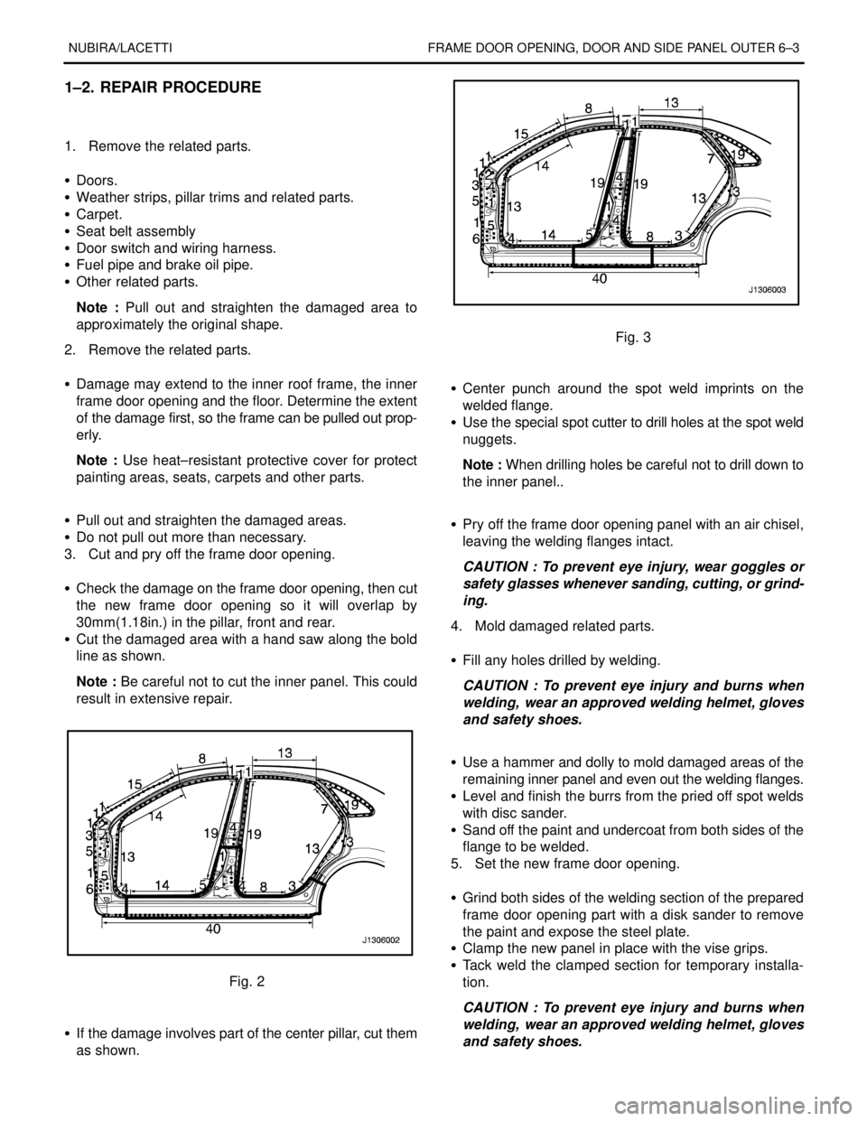
3. Cut and pry off the frame door opening.
S Check the damage on the frame door opening, then cut
the new frame door opening so it will overlap by
30mm(1.18in.) in the pillar, front and rear.
S Cut the damaged area with a hand saw along the bold
line as shown.
Note : Be careful not to cut the inner panel. This could
result in extensive repair.
Fig. 2
S If the damage involves part of the center pillar, cut them
as shown.
Fig. 3
S Center punch around the spot weld imprints on the
welded flange.
S Use the special spot cutter to drill holes at the spot weld
nuggets.
Note : When drilling holes be careful not to drill down to
the inner panel..
S Pry off the frame door opening panel with an air chisel,
leaving the welding flanges intact.
CAUTION : To prevent eye injury, wear goggles or
safety glasses whenever sanding, cutting, or grind-
ing.
4. Mold damaged related parts.
S Fill any holes drilled by welding.
CAUTION : To prevent eye injury and burns when
welding, wear an approved welding helmet, gloves
and safety shoes.
S Use a hammer and dolly to mold damaged areas of the
remaining inner panel and even out the welding flanges.
S Level and finish the burrs from the pried off spot welds
with disc sander.
S Sand off the paint and undercoat from both sides of the
flange to be welded.
5. Set the new frame door opening.
S Grind both sides of the welding section of the prepared
frame door opening part with a disk sander to remove
the paint and expose the steel plate.
S Clamp the new panel in place with the vise grips.
S Tack weld the clamped section for temporary installa-
tion.
CAUTION : To prevent eye injury and burns when
welding, wear an approved welding helmet, gloves
and safety shoes.
Page 2575 of 2643
6–10 FRAME DOOR OPENING, DOOR AND SIDE PANEL OUTER NUBIRA/LACETTI
3–2. REPAIR PROCEDURE
1. Remove the related parts.
S Rear and trunk trims.
S Rear combination lamps and wiring harness.
S Rear bumper and related parts.
S Rear seat and rear seat belt.
S Chassis and fuel parts.
S Other related parts.
CAUTION : Do not smoke while working near the
fuel system. Keep open flame away from the fuel
system. If necessary, remove the fuel tank and off
lines.
2. Pull out and straighten the damaged area to approxi-
mately the original shape.
S Attach the car to the frame straightener by tightening the
underbody clamps at the four designated support points.
S Before cutting off the damaged sections, pull them out
so that they are restored to the original shape.
S Do not pull out more than necessary.
S Pull out and straighten the damaged areas of the rear
side outer panel, side inner panel and wheelhouse inner.
Note : Check the rear door locking and unlocking condi-
tion.
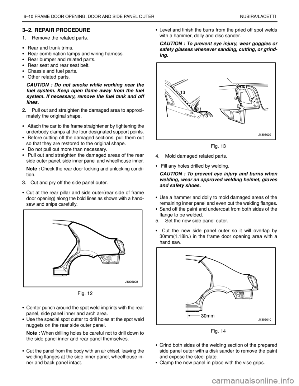
3. Cut and pry off the side panel outer.
S Cut at the rear pillar and side outer(rear side of frame
door opening) along the bold lines as shown with a hand-
saw and snips carefully.
Fig. 12
S Center punch around the spot weld imprints with the rear
panel, side panel inner and arch area.
S Use the special spot cutter to drill holes at the spot weld
nuggets on the rear side outer panel.
Note : When drilling holes be careful not to drill down to
the side panel inner and rear panel themselves.
S Cut the panel from the body with an air chisel, leaving the
welding flanges at the side inner panel, wheelhouse in-
ner and back panel intact.S Level and finish the burrs from the pried off spot welds
with a hammer, dolly and disc sander.
CAUTION : To prevent eye injury, wear goggles or
safety glasses whenever sanding, cutting, or grind-
ing.
Fig. 13
4. Mold damaged related parts.
S Fill any holes drilled by welding.
CAUTION : To prevent eye injury and burns when
welding, wear an approved welding helmet, gloves
and safety shoes.
S Use a hammer and dolly to mold damaged areas of the
remaining inner panel and even out the welding flanges.
S Sand off the paint and undercoat from both sides of the
flange to be welded.
5. Set the new side panel outer.
S Cut the new side panel outer so it will overlap by
30mm(1.18in.) in the frame door opening area with a
hand saw.
Fig. 14
S Grind both sides of the welding section of the prepared
side panel outer with a disk sander to remove the paint
and expose the steel plate.
S Clamp the new panel in place with the vise grips.