2004 DAEWOO NUBIRA fuel
[x] Cancel search: fuelPage 917 of 2643

2B – 10IWHEEL ALIGNMENT
DAEWOO V–121 BL4
GENERAL DESCRIPTION
AND SYSTEM OPERATION
FOUR WHEEL ALIGNMENT
The first responsibility of engineering is to design safe
steering and suspension systems. Each component must
be strong enough to withstand and absorb extreme pun-
ishment. Both the steering system and the front and the
rear suspension must function geometrically with the body
mass.
The steering and the suspension systems require that the
front wheels self–return and that the tire rolling effort and
the road friction be held to a negligible force in order to al-
low the customer to direct the vehicle with the least effort
and the most comfort.
A complete wheel alignment check should include mea-
surements of the rear toe and camber.
Four–wheel alignment assures that all four wheels will be
running in precisely the same direction.
When the vehicle is geometrically aligned, fuel economy
and tire life are at their peak, and steering and perfor-
mance are maximized.
TOE
Toe–in is the turning in of the tires, while toe–out is the
turning out of the tires from the geometric centerline or
thrust line. The toe ensures parallel rolling of the wheels.
The toe serves to offset the small deflections of the wheel
support system which occur when the vehicle is rolling for-
ward. The specified toe angle is the setting which achieves
0 degrees of toe when the vehicle is moving.
Incorrect toe–in or toe–out will cause tire wear and re-
duced fuel economy. As the individual steering and sus-
pension components wear from vehicle mileage, addition-
al toe will be needed to compensate for the wear.
Always correct the toe dimension last.
CASTER
Caster is the tilting of the uppermost point of the steering
axis either forward or backward from the vertical when
viewed from the side of the vehicle. A backward tilt is posi-
tive, and a forward tilt is negative. Caster influences direc-
tional control of the steering but does not affect tire wear.
Weak springs or overloading a vehicle will affect caster.
One wheel with more positive caster will pull toward the
center of the car. This condition will cause the car to move
or lean toward the side with the least amount of positive
caster. Caster is measured in degrees and is not adjust-
able.
CAMBER
Camber is the tilting of the top of the tire from the vertical
when viewed from the front of the vehicle. When the tires
tilt outward, the camber is positive. When the tires tilt in-
ward, the camber is negative. The camber angle is mea-
sured in degrees from the vertical. Camber influences
both directional control and tire wear.
If the vehicle has too much positive camber, the outside
shoulder of the tire will wear. If the vehicle has too much
negative camber, the inside shoulder of the tire will wear.
Camber is not adjustable.
STEERING AXIS INCLINATION
Steering Axis Inclination (SAI) is the tilt at the top of the
steering knuckle from the vertical. Measure the SAI angle
from the true vertical to a line through the center of the strut
and the lower ball joint as viewed from the front of the ve-
hicle.
SAI helps the vehicle track straight down the road and as-
sists the wheel back into the straight ahead position. SAI
on front wheel drive vehicles should be negative.
INCLUDED ANGLE
The included angle is the angle measured from the cam-
ber angle to the line through the center of the strut and the
lower ball joint as viewed from the front of the vehicle.
The included angle is calculated in degrees. Most align-
ment racks will not measure the included angle directly. To
determine the included angle, subtract the negative or add
the positive camber readings to the Steering Axis Inclina-
tion (SAI).
SCRUB RADIUS
The scrub radius is the distance between true vertical and
the line through the center of the strut and lower ball joint
to the road surface. Scrub radius is built into the design of
the vehicle. Scrub radius is not adjustable.
SETBACK
The setback is the distance in which one front hub and
bearing assembly may be rearward of the other front hub
and bearing assembly. Setback is primarily caused by a
road hazard or vehicle collision.
TURNING ANGLE
The turning angle is the angle of each front wheel to the
vertical when the vehicle is making a turn.
Page 919 of 2643

2C – 2IFRONT SUSPENSION
DAEWOO V–121 BL4
SPECIFICATIONS
GENERAL SPECIFICATIONS
ApplicationTrim Height
Center of Front Wheel to Bottom of Front Wheel Well368 mm (14.4 in.)
Center of Rear Wheel to Bottom of Rear Wheel Well367 mm (14.4 in.)
* CONDITION : Full Fuel in the Tank
FASTENER TIGHTENING SPECIFICATIONS
ApplicationNSmLb–FtLb–In
Ball Joint Pinch Bolt Nut6044–
Ball Joint–to–Control Arm Nuts10074–
Front Control Arm–to–Crossmember Bolt12592–
Rear Contral Arm–to–Crossmember Bolt11 081–
Crossmember Link–to–Crossmember Bolt11 484–
Crossmember Link–to–Transaxle Bracket Nut169125–
Drive Axle–to–Hub Caulking Nut300221–
Front Crossmember–to–Body Bolts13096–
Piston Rod Nut7555–
Rear Crossmember–to–Body Bolts196145–
Stabilizer Link–to–Strut Assembly Nut4735–
Stabilizer Shaft–to–Crossmember Clamp Bolts2518–
Stabilizer Shaft–to–Stabilizer Link Nut4735–
Steering Knuckle–to–Strut Assembly Nuts/Bolts12089–
Strut Assembly–to–Body Nut6548–
Page 944 of 2643

2D – 2IREAR SUSPENSION
DAEWOO V–121 BL4
SPECIFICATIONS
FASTENER TIGHTENING SPECIFICATIONS
ApplicationNSmLb–FtLb–In
Crossmember–to–Body Bolts11 283–
Strut Dampener–to–Strut Mount Nut7555–
Rear Parallel Link–to–Crossmember Bolt9066–
Front Parallel Link–to–Knuckle Bolt12089–
Fuel Filler Hose Shield Bolt2015–
Knuckle–to–Strut Assembly Nuts10074–
Rear Parallel Link–to–Knuckle Bolt9066–
Rear Trailing Link–to–Trailing Link Bracket Nut10074–
Rear Trailing Link–to–Knuckle Nut150111–
Stabilizer Link–to–Strut Assembly Nut4735–
Stabilizer Shaft Clamp Bolts4030–
Stabilizer Shaft–to–Stabilizer Link Nut4735–
Strut Mount–to–Body Nuts3022–
Trailing Link Bracket–to–Body Bolts7052–
Trailing Link–to–Trailing Link Bracket Nut10074–
Rear Hub Assembly Bolts6548–
SPECIAL TOOLS
SPECIAL TOOLS TABLE
J–42468
Front Strut Mount
Nut WrenchKM–329–A
Spring Compressor
Page 1014 of 2643
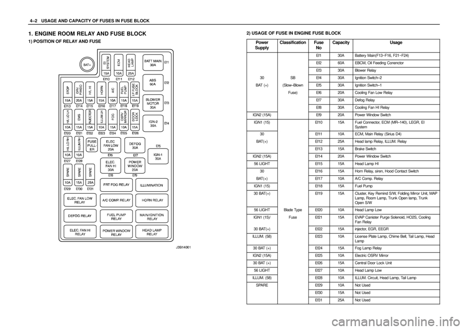
4–2WUSAGE AND CAPACITY OF FUSES IN FUSE BLOCK
1. ENGINE ROOM RELAY AND FUSE BLOCK
1) POSITION OF RELAY AND FUSE
2) USAGE OF FUSE IN ENGINE FUSE BLOCK
Power
Supply
ClassificationFuse
NoCapacityUsage
Ef130ABattery Main(F13~F16, F21~F24)
Ef260AEBCM, Oil Feeding Conenctor
Ef330ABlower Relay
30SBEf430AIgnition Switch–2
BAT (+)(Slow–BlownEf530AIgnition Switch–1
Fuse)Ef620ACooling Fan Low Relay
Ef730ADefog Relay
Ef830ACooling Fan HI Relay
IGN2 (15A)Ef920APower Window Switch
IGN1 (15)Ef1015AFuel Connector, ECM (MR–140), LEGR, EI
System
30Ef1110AECM, Main Relay (Sirius D4)
BAT(+)Ef1225AHead lamp Relay, ILLUM. Relay
Ef1315ABrake Switch
IGN2 (15A)Ef1420APower Window Switch
56 LIGHTEf1515AHead Lamp HI
30Ef1615AHorn Relay, siren, Hood Contact Switch
BAT(+)Ef1710AA/C Comp. Relay
IGN1 (15)Ef1815AFuel Pump
30 BAT(+)Ef1915ACluster, Key Remind S/W, Folding Mirror Unit, MAP
Lamp, Room Lamp, Trunk Open lamp, Trunk
Open S/W
56 LIGHTBlade TypeEf2010AHead Lamp Low
IGN1 (15)/FuseEf2115AEVAP Canister Purge Solenoid, HO2S, Cooling
Fan Relay
30 BAT(+)Ef2215Ainjector, EGR, EEGR
ILLUM. (58)Ef2310ALicense Plate Lamp, Chime Bell, Tail Lamp, Head
Lamp
30 BAT (+)Ef2415AFog Lamp Relay
IGN2 (15A)Ef2510AElectric OSRV Mirror
30 BAT (+)Ef2615ACentral Door Lock Unit
56 LIGHTEf2710AHead Lamp Low
ILLUM. (58)Ef2810AILLUM. Circuit, Head Lamp, Tail Lamp
SPAREEf2910ANot Used
Ef3015ANot Used
Ef3125ANot Used
Page 1016 of 2643
4–4WUSAGE AND CAPACITY OF FUSES IN FUSE BLOCK
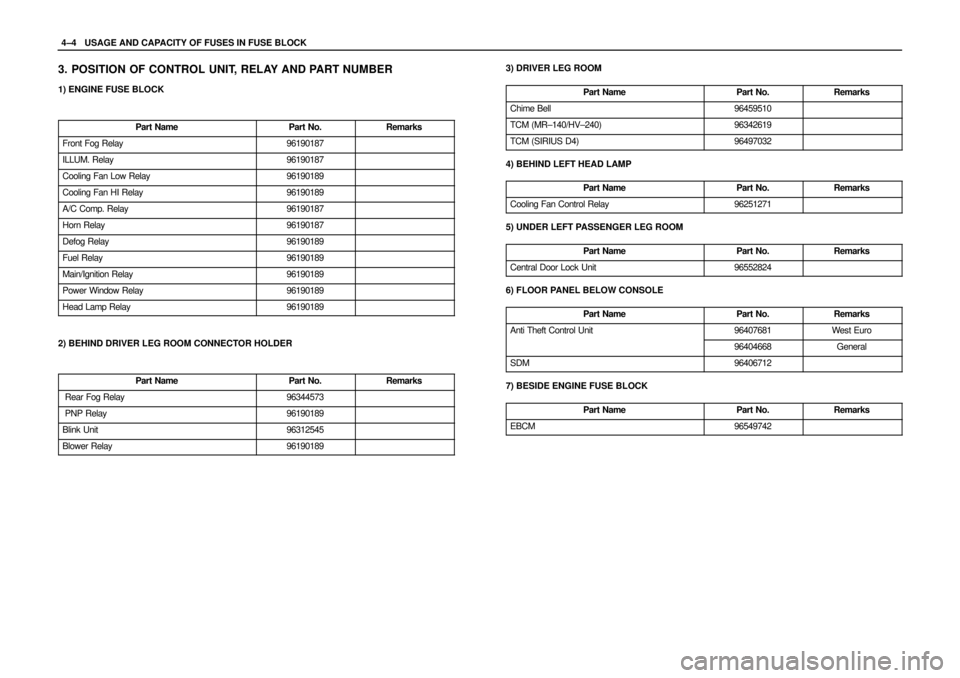
3. POSITION OF CONTROL UNIT, RELAY AND PART NUMBER
1) ENGINE FUSE BLOCK
Part Name
Part No.Remarks
Front Fog Relay96190187
ILLUM. Relay96190187
Cooling Fan Low Relay96190189
Cooling Fan HI Relay96190189
A/C Comp. Relay96190187
Horn Relay96190187
Defog Relay96190189
Fuel Relay96190189
Main/Ignition Relay96190189
Power Window Relay96190189
Head Lamp Relay96190189
2) BEHIND DRIVER LEG ROOM CONNECTOR HOLDER
Part Name
Part No.Remarks
Rear Fog Relay96344573
PNP Relay96190189
Blink Unit96312545
Blower Relay96190189
3) DRIVER LEG ROOM
Part Name
Part No.Remarks
Chime Bell96459510
TCM (MR–140/HV–240)96342619
TCM (SIRIUS D4)96497032
4) BEHIND LEFT HEAD LAMP
Part Name
Part No.Remarks
Cooling Fan Control Relay96251271
5) UNDER LEFT PASSENGER LEG ROOM
Part Name
Part No.Remarks
Central Door Lock Unit96552824
6) FLOOR PANEL BELOW CONSOLE
Part Name
Part No.Remarks
Anti Theft Control Unit96407681Wes t Euro
96404668General
SDM96406712
7) BESIDE ENGINE FUSE BLOCK
Part Name
Part No.Remarks
EBCM96549742
Page 1158 of 2643
4G – 6IPARKING BRAKE
DAEWOO V–121 BL4
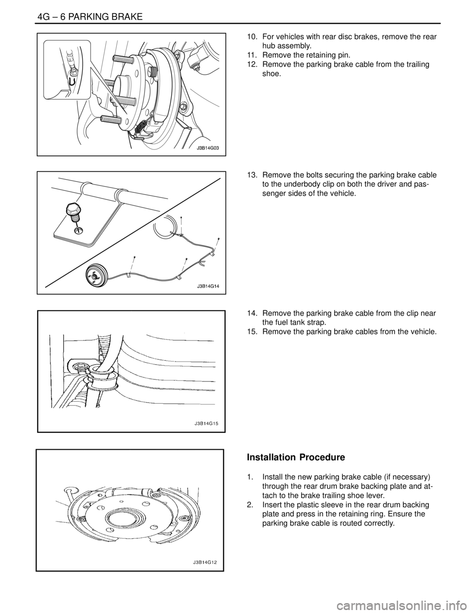
10. For vehicles with rear disc brakes, remove the rear
hub assembly.
11. Remove the retaining pin.
12. Remove the parking brake cable from the trailing
shoe.
13. Remove the bolts securing the parking brake cable
to the underbody clip on both the driver and pas-
senger sides of the vehicle.
14. Remove the parking brake cable from the clip near
the fuel tank strap.
15. Remove the parking brake cables from the vehicle.
Installation Procedure
1. Install the new parking brake cable (if necessary)
through the rear drum brake backing plate and at-
tach to the brake trailing shoe lever.
2. Insert the plastic sleeve in the rear drum backing
plate and press in the retaining ring. Ensure the
parking brake cable is routed correctly.
Page 1159 of 2643
PARKING BRAKE 4G – 7
DAEWOO V–121 BL4
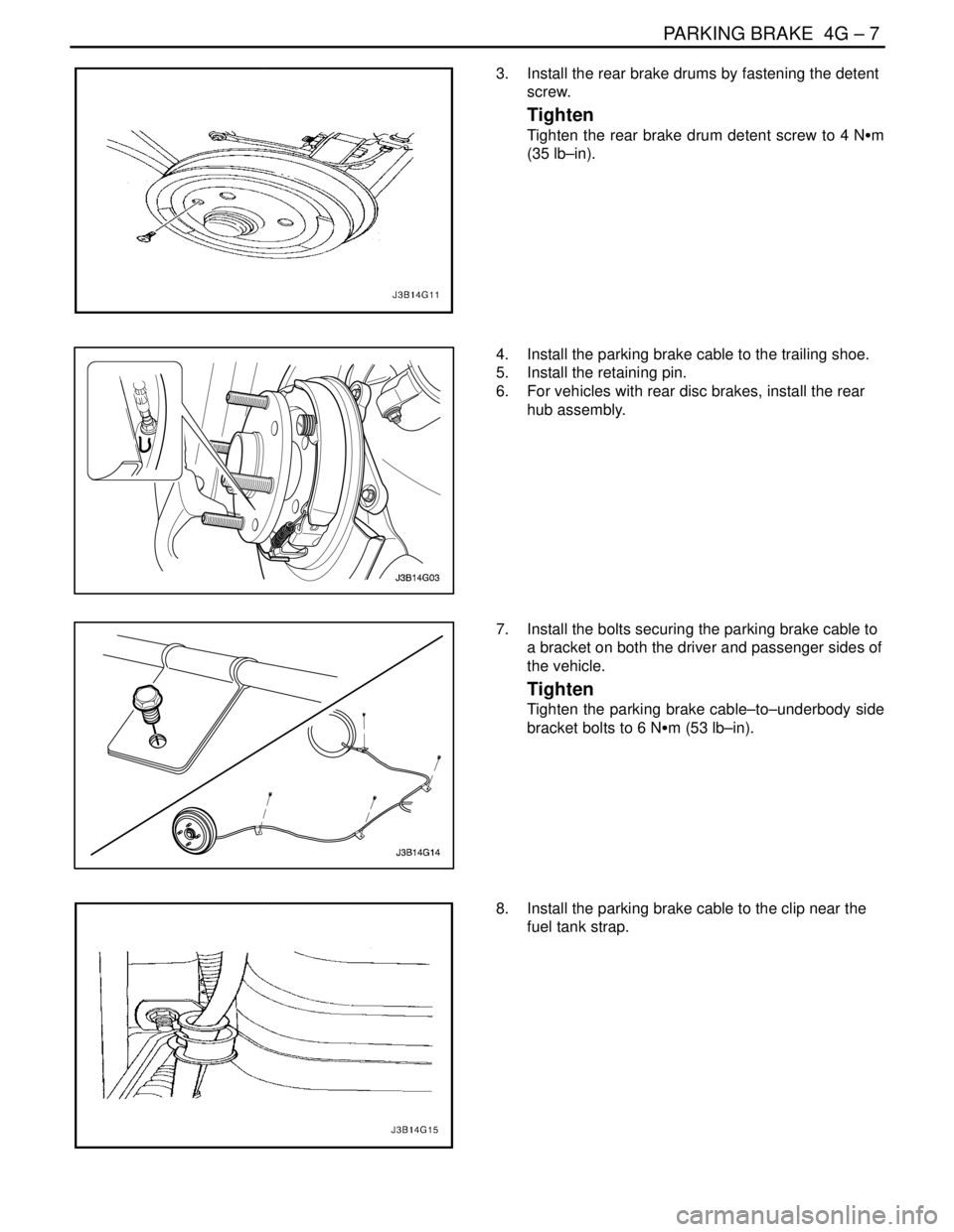
3. Install the rear brake drums by fastening the detent
screw.
Tighten
Tighten the rear brake drum detent screw to 4 NSm
(35 lb–in).
4. Install the parking brake cable to the trailing shoe.
5. Install the retaining pin.
6. For vehicles with rear disc brakes, install the rear
hub assembly.
7. Install the bolts securing the parking brake cable to
a bracket on both the driver and passenger sides of
the vehicle.
Tighten
Tighten the parking brake cable–to–underbody side
bracket bolts to 6 NSm (53 lb–in).
8. Install the parking brake cable to the clip near the
fuel tank strap.
Page 1162 of 2643
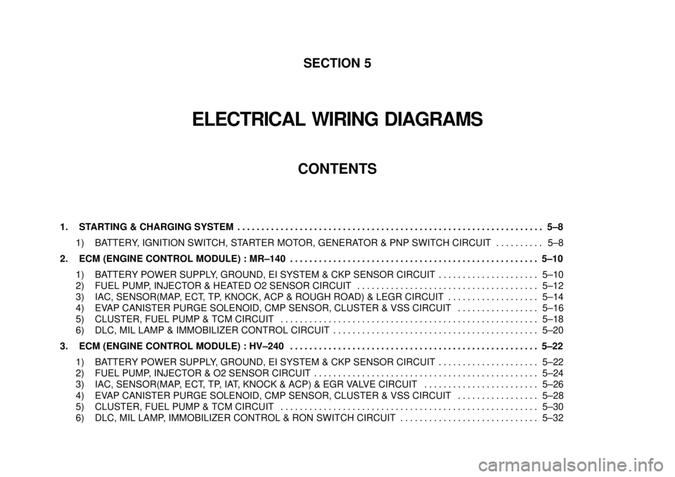
SECTION 5
ELECTRICAL WIRING DIAGRAMS
CONTENTS
1. STARTING & CHARGING SYSTEM5–8 . . . . . . . . . . . . . . . . . . . . . . . . . . . . . . . . . . . . . . . . . . . . . . . . . . . . . . . . . . . . . . . .
1) BATTERY, IGNITION SWITCH, STARTER MOTOR, GENERATOR & PNP SWITCH CIRCUIT 5–8. . . . . . . . . .
2. ECM (ENGINE CONTROL MODULE) : MR–140 5–10. . . . . . . . . . . . . . . . . . . . . . . . . . . . . . . . . . . . . . . . . . . . . . . . . . . .
1) BATTERY POWER SUPPLY, GROUND, EI SYSTEM & CKP SENSOR CIRCUIT 5–10. . . . . . . . . . . . . . . . . . . . .
2) FUEL PUMP, INJECTOR & HEATED O2 SENSOR CIRCUIT 5–12. . . . . . . . . . . . . . . . . . . . . . . . . . . . . . . . . . . . . .
3) IAC, SENSOR(MAP, ECT, TP, KNOCK, ACP & ROUGH ROAD) & LEGR CIRCUIT 5–14. . . . . . . . . . . . . . . . . . .
4) EVAP CANISTER PURGE SOLENOID, CMP SENSOR, CLUSTER & VSS CIRCUIT 5–16. . . . . . . . . . . . . . . . .
5) CLUSTER, FUEL PUMP & TCM CIRCUIT 5–18. . . . . . . . . . . . . . . . . . . . . . . . . . . . . . . . . . . . . . . . . . . . . . . . . . . . . .
6) DLC, MIL LAMP & IMMOBILIZER CONTROL CIRCUIT 5–20. . . . . . . . . . . . . . . . . . . . . . . . . . . . . . . . . . . . . . . . . . .
3. ECM (ENGINE CONTROL MODULE) : HV–240 5–22. . . . . . . . . . . . . . . . . . . . . . . . . . . . . . . . . . . . . . . . . . . . . . . . . . . .
1) BATTERY POWER SUPPLY, GROUND, EI SYSTEM & CKP SENSOR CIRCUIT 5–22. . . . . . . . . . . . . . . . . . . . .
2) FUEL PUMP, INJECTOR & O2 SENSOR CIRCUIT 5–24. . . . . . . . . . . . . . . . . . . . . . . . . . . . . . . . . . . . . . . . . . . . . . .
3) IAC, SENSOR(MAP, ECT, TP, IAT, KNOCK & ACP) & EGR VALVE CIRCUIT 5–26. . . . . . . . . . . . . . . . . . . . . . . .
4) EVAP CANISTER PURGE SOLENOID, CMP SENSOR, CLUSTER & VSS CIRCUIT 5–28. . . . . . . . . . . . . . . . .
5) CLUSTER, FUEL PUMP & TCM CIRCUIT 5–30. . . . . . . . . . . . . . . . . . . . . . . . . . . . . . . . . . . . . . . . . . . . . . . . . . . . . .
6) DLC, MIL LAMP, IMMOBILIZER CONTROL & RON SWITCH CIRCUIT 5–32. . . . . . . . . . . . . . . . . . . . . . . . . . . . .