Page 1555 of 2643
5A1 – 206IZF 4 HP 16 AUTOMATIC TRANSAXLE
DAEWOO V–121 BL4
Installation Procedure
1. Install the left transaxle mount bracket cage bolts
and nut.
Tighten
S Tighten the left transaxle mount bracket cage
bolt (a) to 110 NSm (81 lb–ft).
S Tighten the left transaxle mount bracket cage
bolt (b) to 65 NSm (48 lb–ft).
S Tighten the nut (c) to 65 NSm (48 lb–ft).
2. Install the left transaxle mounting bolts to 48 NSm
(35 lb–ft).
3. Remove the engine support fixture DW110–060.
4. Install the battery. Refer to Section 1E, Engine
Electrical.
TRANSAXLE ASSEMBLY
Tools Required
DW110–060 Engine Support Fixture
DW260–010 Transaxle Support Fixture
Removal Procedure
1. Disconnect the negative battery cable.
2. Position the select lever park position.
3. Remove the battery. Refer to Section 1E, Engine
Electrical.
4. Install the engine support fixture DW110–060.
Page 1556 of 2643
ZF 4 HP 16 AUTOMATIC TRANSAXLE 5A1 – 207
DAEWOO V–121 BL4
5. Disconnect the transaxle wiring harness from the
transaxle.
6. Disconnect the park/neutral position switch electri-
cal connector.
7. Remove the clips from the shift control cable and
disconnect the shift control cable from the trans-
axle.
8. Remove the upper transaxle–to–engine bolts.
9. Remove the left transaxle mounting bracket. Refer
to ”Left Transaxle Mounting Bracket” in this sec-
tion.
Page 1557 of 2643
5A1 – 208IZF 4 HP 16 AUTOMATIC TRANSAXLE
DAEWOO V–121 BL4
10. Raise and suitably support the vehicle.
11. Drain the transaxle fluid.
12. Remove the oil cooler pipes from the transaxle. Re-
fer to ”Oil Cooler Pipes/Hoses” in this section.
13. Remove the drive axle. Refer to Section 3A, Auto-
matic Drive Axle.
14. Remove the starter motor. Refer to Section 1E, En-
gine Electrical.
15. Remove the torque converter bolts.
16. Support the transaxle.
17. Remove the rear transaxle mounting bracket bolts
(a) and damping block connection bolt and nut (b).
18. Support the transaxle assembly using the transaxle
support fixture DW260–010.
Page 1558 of 2643
ZF 4 HP 16 AUTOMATIC TRANSAXLE 5A1 – 209
DAEWOO V–121 BL4
19. Remove the lower engine–to–transaxle bolts.
20. Remove the transaxle assembly.
Installation Procedure
1. Install the transaxle into the vehicle.
2. Support the transaxle assembly using the transaxle
support fixture DW260–010.
3. Install the lower engine–to–transaxle bolts.
Tighten
Tighten the lower engine–to–transaxle bolts (a) to 75
NSm (55 lb–ft).
Tighten the lower engine–to–transaxle bolt (b) to 21
NSm (15 lb–ft).
Tighten the lower engine–to–transaxle bolt (c) to 31
NSm (23 lb–ft).
Page 1559 of 2643
5A1 – 210IZF 4 HP 16 AUTOMATIC TRANSAXLE
DAEWOO V–121 BL4
4. Install the rear transaxle mounting bracket bolts (a).
Tighten
Tighten the rear transaxle mounting bracket bolts (a)
to 62 NSm (45 lb–ft).
5. Install the damping block connection bolt and nut
(b).
Tighten
Tighten the damping block connection bolt and nut (b)
to 68 NSm (50 lb–ft).
6. Install the torque converter bolts.
7. Install the starter motor. Refer to Section 1E, En-
gine Electrical.
8. Install the drive axle. Refer to Section 3A, Automat-
ic Drive Axle.
9. Install the oil cooler pipes from the transaxle. Refer
to ”Oil Cooler Pipes/Hoses” in this section.
10. Lower the vehicle.
11. Install the left transaxle mounting bracket. Refer to
”Left Transaxle Mounting Bracket” in this section.
Page 1560 of 2643
ZF 4 HP 16 AUTOMATIC TRANSAXLE 5A1 – 211
DAEWOO V–121 BL4
12. Install the upper transaxle–to–engine bolts.
Tighten
Tighten the upper transaxle–to–engine bolts to 75
NSm (55 lb–ft).
13. Install the clips to the shift control cable and con-
nect the shift cable.
14. Install the park/neutral position switch electrical
connector.
15. Connect the transaxle wiring harness to the trans-
axle.
16. Remove the engine support fixture DW110–060.
17. Install the battery. Refer to Section 1E, Engine
Electrical.
18. Add the transaxle fluid. Refer to ”Transaxle Fluid
Level Checking Procedure” in this section.
19. Connect the negative battery cable.
Page 1561 of 2643

5A1 – 212IZF 4 HP 16 AUTOMATIC TRANSAXLE
DAEWOO V–121 BL4
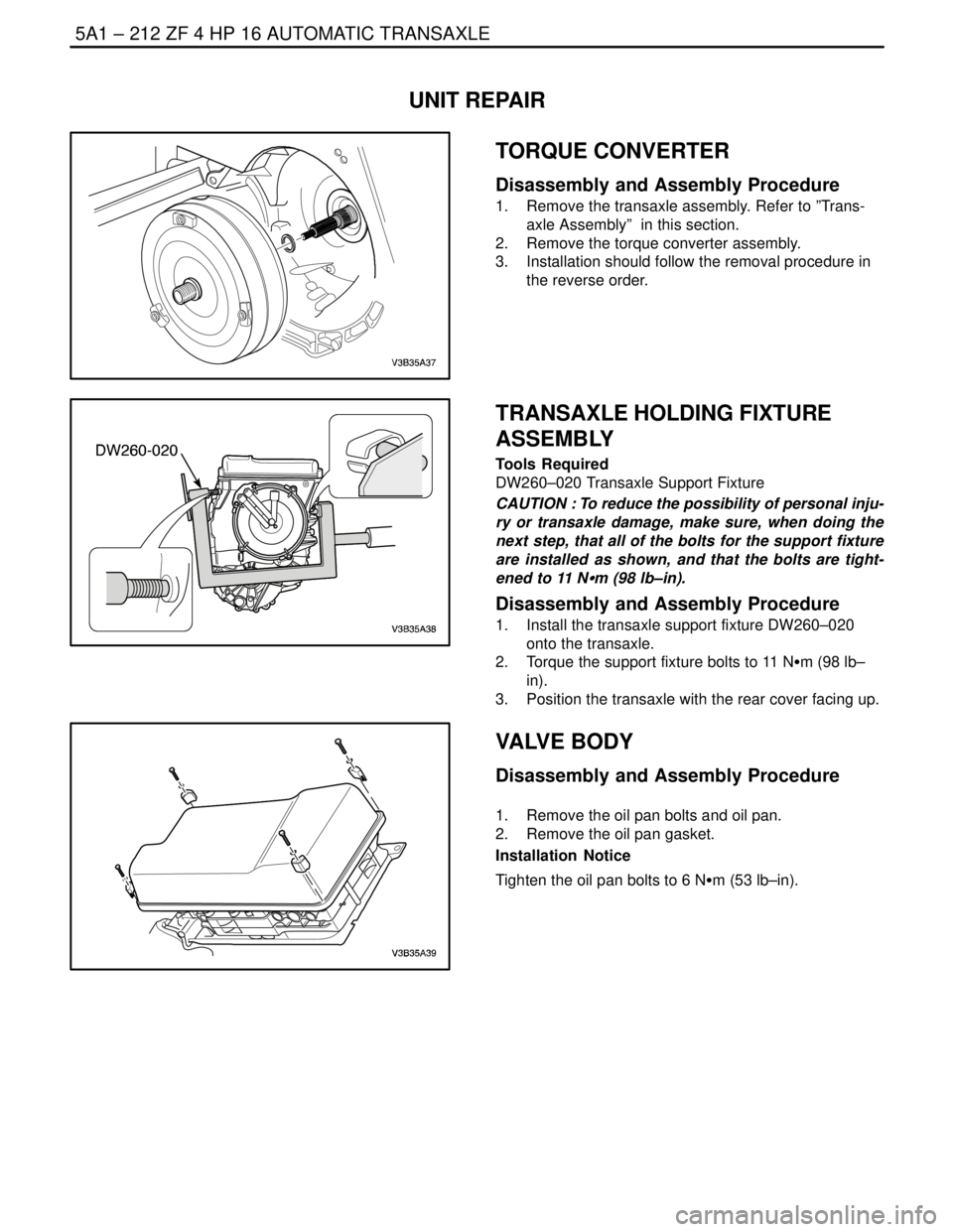
UNIT REPAIR
TORQUE CONVERTER
Disassembly and Assembly Procedure
1. Remove the transaxle assembly. Refer to ”Trans-
axle Assembly” in this section.
2. Remove the torque converter assembly.
3. Installation should follow the removal procedure in
the reverse order.
TRANSAXLE HOLDING FIXTURE
ASSEMBLY
Tools Required
DW260–020 Transaxle Support Fixture
CAUTION : To reduce the possibility of personal inju-
ry or transaxle damage, make sure, when doing the
next step, that all of the bolts for the support fixture
are installed as shown, and that the bolts are tight-
ened to 11 NSm (98 lb–in).
Disassembly and Assembly Procedure
1. Install the transaxle support fixture DW260–020
onto the transaxle.
2. Torque the support fixture bolts to 11 NSm (98 lb–
in).
3. Position the transaxle with the rear cover facing up.
VALVE BODY
Disassembly and Assembly Procedure
1. Remove the oil pan bolts and oil pan.
2. Remove the oil pan gasket.
Installation Notice
Tighten the oil pan bolts to 6 NSm (53 lb–in).
Page 1562 of 2643

ZF 4 HP 16 AUTOMATIC TRANSAXLE 5A1 – 213
DAEWOO V–121 BL4
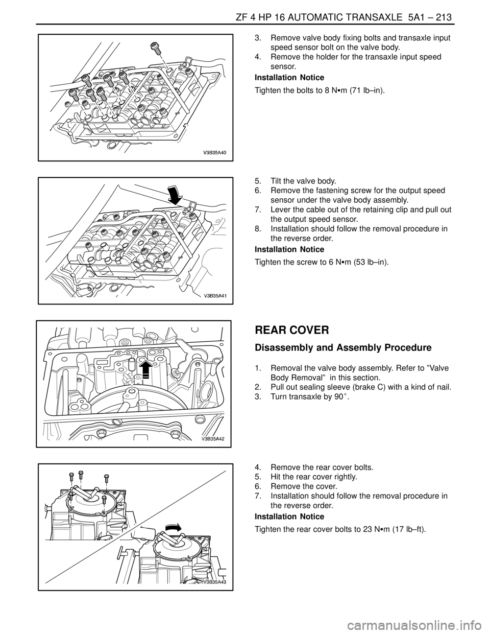
3. Remove valve body fixing bolts and transaxle input
speed sensor bolt on the valve body.
4. Remove the holder for the transaxle input speed
sensor.
Installation Notice
Tighten the bolts to 8 NSm (71 lb–in).
5. Tilt the valve body.
6. Remove the fastening screw for the output speed
sensor under the valve body assembly.
7. Lever the cable out of the retaining clip and pull out
the output speed sensor.
8. Installation should follow the removal procedure in
the reverse order.
Installation Notice
Tighten the screw to 6 NSm (53 lb–in).
REAR COVER
Disassembly and Assembly Procedure
1. Removal the valve body assembly. Refer to ”Valve
Body Removal” in this section.
2. Pull out sealing sleeve (brake C) with a kind of nail.
3. Turn transaxle by 90°.
4. Remove the rear cover bolts.
5. Hit the rear cover rightly.
6. Remove the cover.
7. Installation should follow the removal procedure in
the reverse order.
Installation Notice
Tighten the rear cover bolts to 23 NSm (17 lb–ft).