Page 1539 of 2643

5A1 – 190IZF 4 HP 16 AUTOMATIC TRANSAXLE
DAEWOO V–121 BL4
MAINTENANCE AND REPAIR
ON–VEHICLE SERVICE
TRANSAXLE FLUID LEVEL
CHECKING PROCEDURE
Tools Required
DW260–070 Plug Remover/Installer
Inspection Procedure
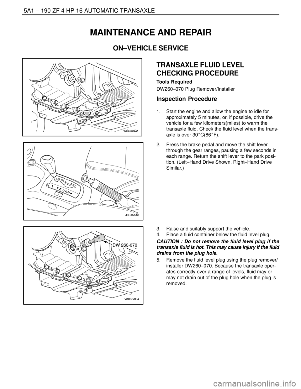
1. Start the engine and allow the engine to idle for
approximately 5 minutes, or, if possible, drive the
vehicle for a few kilometers(miles) to warm the
transaxle fluid. Check the fluid level when the trans-
axle is over 30°C(86°F).
2. Press the brake pedal and move the shift lever
through the gear ranges, pausing a few seconds in
each range. Return the shift lever to the park posi-
tion. (Left–Hand Drive Shown, Right–Hand Drive
Similar.)
3. Raise and suitably support the vehicle.
4. Place a fluid container below the fluid level plug.
CAUTION : Do not remove the fluid level plug if the
transaxle fluid is hot. This may cause injury if the fluid
drains from the plug hole.
5. Remove the fluid level plug using the plug remover/
installer DW260–070. Because the transaxle oper-
ates correctly over a range of levels, fluid may or
may not drain out of the plug hole when the plug is
removed.
Page 1540 of 2643

ZF 4 HP 16 AUTOMATIC TRANSAXLE 5A1 – 191
DAEWOO V–121 BL4
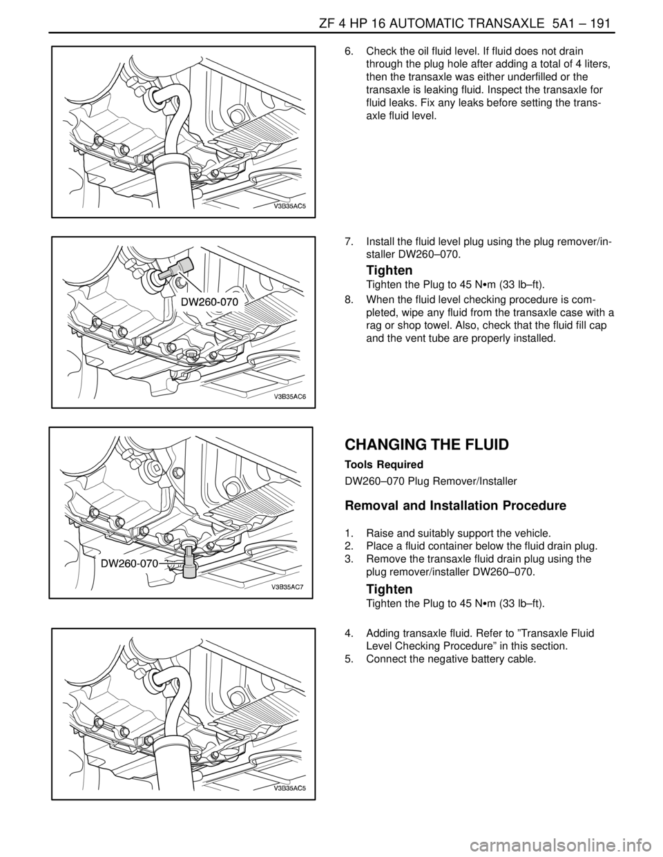
6. Check the oil fluid level. If fluid does not drain
through the plug hole after adding a total of 4 liters,
then the transaxle was either underfilled or the
transaxle is leaking fluid. Inspect the transaxle for
fluid leaks. Fix any leaks before setting the trans-
axle fluid level.
7. Install the fluid level plug using the plug remover/in-
staller DW260–070.
Tighten
Tighten the Plug to 45 NSm (33 lb–ft).
8. When the fluid level checking procedure is com-
pleted, wipe any fluid from the transaxle case with a
rag or shop towel. Also, check that the fluid fill cap
and the vent tube are properly installed.
CHANGING THE FLUID
Tools Required
DW260–070 Plug Remover/Installer
Removal and Installation Procedure
1. Raise and suitably support the vehicle.
2. Place a fluid container below the fluid drain plug.
3. Remove the transaxle fluid drain plug using the
plug remover/installer DW260–070.
Tighten
Tighten the Plug to 45 NSm (33 lb–ft).
4. Adding transaxle fluid. Refer to ”Transaxle Fluid
Level Checking Procedure” in this section.
5. Connect the negative battery cable.
Page 1541 of 2643

5A1 – 192IZF 4 HP 16 AUTOMATIC TRANSAXLE
DAEWOO V–121 BL4
FLUID LEVEL SET AFTER SERVICE
1. Add transaxle fluid through the fill cap hole prior to
adjusting the fluid level. The amount of fluid to add
should be based on the type of service done.
Adjustment Notice
S Use ESSO LT 71141 transaxle fluid only.
S Oil pan removed : 4L (4.2 qt)
S Torque converter removed : 2L (2.1 qt)
S Complete overhaul : 6.7L (7.1qt)
S Drain plug removed : 4L (4.2 qt)
2. Check the transaxle fluid level. Refer to ”Transaxle
Fluid Level Checking Procedure” in this section.
3. Add additional fluid through the fill cap hole in 0.5
liter (0.5 quart) increments until the fluid comes out
through the plug hole.
4. Allow the fluid to finish draining out through the plug
hole, then install the fluid level plug.
5. When the fluid level setting procedure is completed,
wipe any fluid from the transaxle case with a rag or
shop towel. Also, check that the fluid fill cap and the
vent tube are properly installed.
REPAIRING FLUID LEAKS
Locating Leaks
General Method
1. Verify that the leak is transaxle fluid.
2. Thoroughly clean the suspected leak area.
3. Operate the vehicle for about 25 kilometers (15
miles) or until the transaxle reaches normal operat-
ing temperature, 88°C (190°F).
4. Park the vehicle over clean paper or cardboard.
5. Turn the engine off and look for fluid spots on the
paper.
6. Make the necessary repairs to correct the leak.
Powder Method
1. Thoroughly clean the suspected leak area.
2. Apply an aerosol–type powder (foot powder) to the
suspected leak area.
3. Operate the vehicle for about 25 kilometers (15
miles) or until the transaxle reaches normal operat-
ing temperature, 88°C (190°F).
4. Turn the engine off.
5. Inspect the suspected leak area and trace the leak
path through the powder to find the source of the
leak.
6. Make the necessary repairs.
Page 1542 of 2643

ZF 4 HP 16 AUTOMATIC TRANSAXLE 5A1 – 193
DAEWOO V–121 BL4
Repairing the Fluid Leak
The following are potential causes for fluid leaks. Check
and repair, as necessary.
S Fasteners are not tightened to specifications.
S Fastener threads and tapped holes are dirty or cor-
roded.
S Gaskets, seals or sleeves are misaligned, dam-
aged, or warped, or scratched.
S The manual shaft is nicked or damaged.
S There is a loose or worn bearing causing excess
seal or sleeve wear.
S Case or component porosity.
S The fluid level is too high.
S There is a plugged vent or a damaged vent tube.
S There is water or coolant in the fluid.
S Fluid drain back holes are plugged.
CASE POROSITY REPAIR
CAUTION : Epoxy adhesive may cause skin irritations
and eye damage. Read and follow all information on
the container label as provided by the manufacturer.
1. Thoroughly clean the area to be repaired with a
cleaning solvent. Air dry the area.
2. Using instructions from the manufacturer, mix a
sufficient amount of epoxy to make the repair.
3. While the transaxle case is still hot, apply the
epoxy. You can use a clean, dry soldering acid
brush to clean the area and also apply the epoxy
cement. Make certain that the area to be repaired is
fully covered.
4. Allow the epoxy cement to dry for 3 hours before
starting the engine.
5. Repeat the fluid leak diagnosis procedures. Refer
to ”Fluid Leak Diagnosis and Repair” in this sec-
tion.
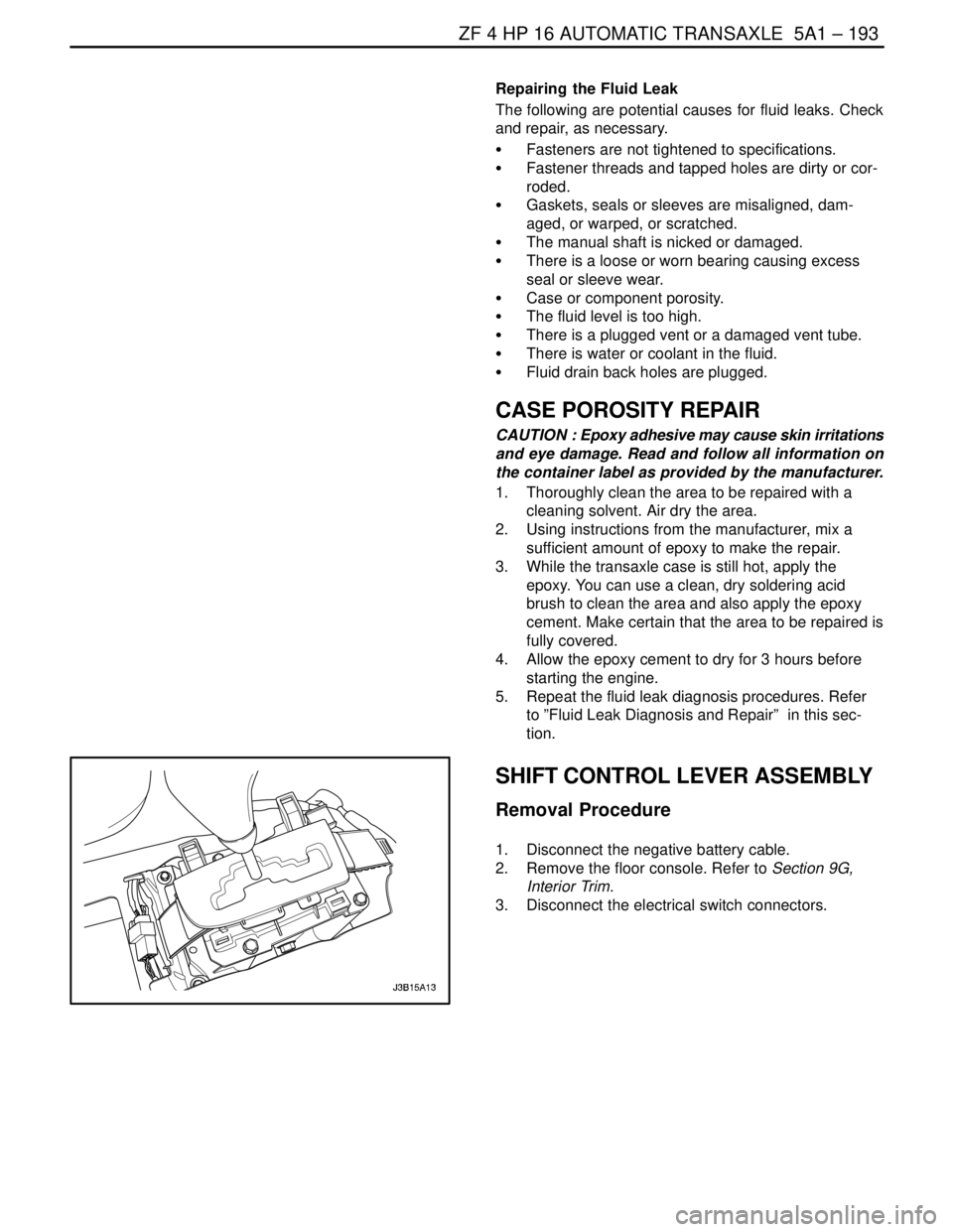
SHIFT CONTROL LEVER ASSEMBLY
Removal Procedure
1. Disconnect the negative battery cable.
2. Remove the floor console. Refer to Section 9G,
Interior Trim.
3. Disconnect the electrical switch connectors.
Page 1543 of 2643
5A1 – 194IZF 4 HP 16 AUTOMATIC TRANSAXLE
DAEWOO V–121 BL4
4. Remove the shift control cable adjuster pinch nut.
5. Remove the cable from the bracket.
6. Remove the bolts and nuts holding the shift control
assembly to the floor panel.
7. Remove the shift control assembly.
Installation Procedure
1. Install the shift control assembly.
Tighten
Tighten the bolts and nuts to 8 NSm (71 lb–in).
2. Install the shift control cable onto the bracket.
3. Install the shift control cable adjuster pinch nut.
Tighten
Tighten the shift control cable adjuster pinch nut to 8
NSm (71 lb–in).
Page 1544 of 2643
ZF 4 HP 16 AUTOMATIC TRANSAXLE 5A1 – 195
DAEWOO V–121 BL4
4. Connect the electrical switch connectors.
5. Install the floor console. Refer to Section 9G, Interi-
or Trim.
6. Connect the negative battery cable.
SHIFT CONTROL CABLE
Removal Procedure
1. Disconnect the negative battery cable.
2. Remove the clip from the selector lever connection
on the transaxle case and disconnect the shift con-
trol cable from the selector lever connection.
3. Remove the clip from the shift control cable at the
transaxle mount connection.
4. Remove the floor console. Refer to Section 9G,
Interior Trim.
5. Loosen the shift control cable adjuster pinch nut.
6. Remove the shift control cable from the shift control
assembly.
7. Remove the shift control cable from the transaxle
mount.
8. Pull the shift control cable through the fire wall of
the vehicle, bringing the rubber grommet with it.
Page 1545 of 2643

5A1 – 196IZF 4 HP 16 AUTOMATIC TRANSAXLE
DAEWOO V–121 BL4
Installation Procedure
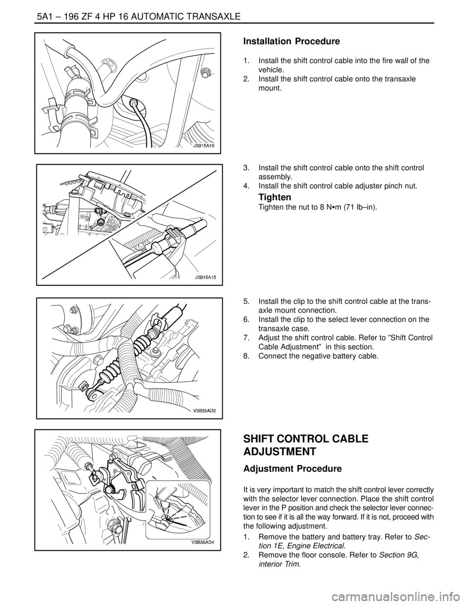
1. Install the shift control cable into the fire wall of the
vehicle.
2. Install the shift control cable onto the transaxle
mount.
3. Install the shift control cable onto the shift control
assembly.
4. Install the shift control cable adjuster pinch nut.
Tighten
Tighten the nut to 8 NSm (71 lb–in).
5. Install the clip to the shift control cable at the trans-
axle mount connection.
6. Install the clip to the select lever connection on the
transaxle case.
7. Adjust the shift control cable. Refer to ”Shift Control
Cable Adjustment” in this section.
8. Connect the negative battery cable.
SHIFT CONTROL CABLE
ADJUSTMENT
Adjustment Procedure
It is very important to match the shift control lever correctly
with the selector lever connection. Place the shift control
lever in the P position and check the selector lever connec-
tion to see if it is all the way forward. If it is not, proceed with
the following adjustment.
1. Remove the battery and battery tray. Refer to Sec-
tion 1E, Engine Electrical.
2. Remove the floor console. Refer to Section 9G,
interior Trim.
Page 1546 of 2643
ZF 4 HP 16 AUTOMATIC TRANSAXLE 5A1 – 197
DAEWOO V–121 BL4
3. Place the shift control lever in the P position.
4. Loosen the pinch bolt nut on the shift control lever.
5. Place the selector lever connection all the way for-
ward on the transaxle case.
6. Insert the shift control cable into the shift control
lever tightly.
7. Secure the shift control cable with the shift control
cable adjuster pinch bolt and nut.
Tighten
Tighten the nut to 8 NSm (71 lb–in).
8. Install the floor console.
9. Install the battery and the battery tray. Refer to
Section 1E, Engine Electrical.
TRANSAXLE CONTROL
MODULE(TCM)
Removal Procedure
1. Disconnect the negative battery cable.
2. Disconnect the wiring connectors.
3. Remove the transaxle control module(TCM) from
the bracket.
Installation Procedure
1. Install the TCM into the bracket.
2. Connect the wiring connectors.
3. Connect the negative battery cable.