Page 1192 of 2643
5–32WELECTRICAL WIRING DIAGRAMS
6) DLC, MIL LAMP IMMOBILIZER & RON SWITCH CIRCUITa. CONNECTOR INFORMATION
CONNECTOR(NO.)
(PIN NO. COLOR)
CONNECTING, WIRING HARNESSCONNECTOR POSITION
C105 (4 Pin, White)Body � Engine Fuse BlockEngine Fuse Block
C108 (24 Pin, Black)Body � EngineLeft Engine Fuse Block
C110 (12 Pin, White)ABS � BodyBelow Engine Fuse Block
C201 (76 Pin, Black)I.P � I.P Fuse BlockI.P Fuse Block
C202 (89 Pin, White)I.P � BodyLeft CO–Driver Leg Room
C206 (22 Pin, White)I.P � TCMUpper Driver Leg Room
C207 (6 Pin, White)Air Bag � I.PUpper Left Driver Leg Room
G104EngineUnder Start Motor
G201I.PLeft I.P Fuse Block
b. CONNECTOR IDENTIFICATION SYMBOL & PIN NUMBER POSITION
J3B1P013
Page 1208 of 2643
5–48WELECTRICAL WIRING DIAGRAMS
8) DLC, MIL LAMP & IMMOBILIZER CONTROL CIRCUITa. CONNECTOR INFORMATION
CONNECTOR(NO.)
(PIN NO. COLOR)
CONNECTING, WIRING HARNESSCONNECTOR POSITION
C105 (4 Pin, White)Body � Engine Fuse BlockEngine Fuse Block
C108 (24 Pin, Black)Body � EngineLeft Engine Fuse Block
C110 (12 Pin, White)ABS � BodyBelow Engine Fuse Block
C201 (76 Pin, Black)I.P � I.P Fuse BlockI.P Fuse Block
C202 (89 Pin, White)I.P � BodyLeft CO–Driver Leg Room
C206 (22 Pin, White)I.P � TCMUpper Driver Leg Room
C207 (6 Pin, White)Air Bag � I.PUpper Left Driver Leg Room
G201I.PLeft I.P Fuse Block
b. CONNECTOR IDENTIFICATION SYMBOL & PIN NUMBER POSITION
J3B1P021
Page 1344 of 2643
5–184WELECTRICAL WIRING DIAGRAMS
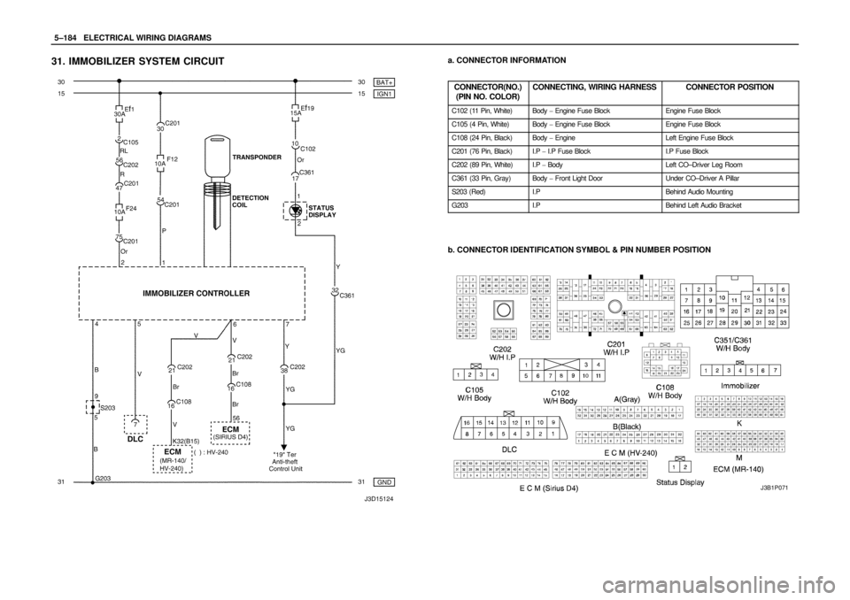
31. IMMOBILIZER SYSTEM CIRCUITa. CONNECTOR INFORMATION
CONNECTOR(NO.)
(PIN NO. COLOR)
CONNECTING, WIRING HARNESSCONNECTOR POSITION
C102 (11 Pin, White)Body � Engine Fuse BlockEngine Fuse Block
C105 (4 Pin, White)Body � Engine Fuse BlockEngine Fuse Block
C108 (24 Pin, Black)Body � EngineLeft Engine Fuse Block
C201 (76 Pin, Black)I.P � I.P Fuse BlockI.P Fuse Block
C202 (89 Pin, White)I.P � BodyLeft CO–Driver Leg Room
C361 (33 Pin, Gray)Body � Front Light DoorUnder CO–Driver A Pillar
S203 (Red)I.PBehind Audio Mounting
G203I.PBehind Left Audio Bracket
b. CONNECTOR IDENTIFICATION SYMBOL & PIN NUMBER POSITION
J3B1P071
Page 1968 of 2643
6E – 14ISTEERING WHEEL AND COLUMN
DAEWOO V–121 BL4
4. With the key in the ignition turned to the position
designated ACC, remove the lock cylinder by
pressing down the detent spring and pulling the
lock cylinder out of the switch cylinder housing.
5. Remove the ignition switch retaining screw.
6. Disconnect the wiring and remove the ignition
switch.
Installation Procedure
1. Install the ignition switch with the ignition switch
retaining screw.
Tighten
Tighten the ignition switch retaining screw to 2.5 NSm
(22 lb–in).
2. Connect the wiring to the ignition switch.
3. Install the lock cylinder.
4. Connect the electrical connector for the immobilizer
detection unit.
5. Install the upper and the lower steering column cov-
er panel with the screws.
Tighten
Tighten the upper and the lower steering column cov-
er panel screws to 2.5 NSm (22 lb–in).
6. Connect the negative battery cable.
Page 1969 of 2643

Important : Remove the steering column only if the follow-
ing conditions")
STEERING WHEEL AND COLUMN 6E – 15
DAEWOO V–121 BL4
STEERING COLUMN
(Left–Hand Drive Shown, Right–Hand Dirve
Similar)
Important : Remove the steering column only if the follow-
ing conditions exist:
S The steering column requires replacement.
S The steering and the ignition lock housing require
replacement.
S Another operation requires the removal of the
steering column.
Notice : The steering column is extremely susceptible to
damage after it has been removed from the vehicle. Drop-
ping the column assembly on its end or hammering the
end of the steering shaft can collapse the steering shaft or
loosen the plastic injections which maintain column rigid-
ity. Leaning on the column can cause it to bend or deform.
Any of the above damage can impair the column’s collaps-
ible design. If it is necessary to remove the steering wheel,
use only the specified steering wheel puller.
Removal Procedure
1. Disconnect the negative battery cable and let the
vehicle sit for 1 minute to deactivate the airbag.
2. Remove the the lower instrument trim panels. Refer
to Section 9E, Instrumentation/Driver Information.
3. Remove the upper and the lower steering column
cover panel by removing the screws.
4. Remove the switch levers. Refer to ”Turn Signal
Switch and Lever” and ”Wiper Switch and Lever” in
this section.
5. Remove the immobilizer module. Refer to Section
9T, Remote Keyless Entry and Anti–theft System.
6. Disconnect the airbag electrical connections.
Page 1972 of 2643
6E – 18ISTEERING WHEEL AND COLUMN
DAEWOO V–121 BL4
6. Connect the ignition switch electrical connection.
7. Connect the airbag electrical connections.
8. Install the switch levers. Refer to ”Turn Signal
Switch and Lever” and ”Wiper Switch and Lever” in
this section.
9. Install the immobilizer module. Refer to Section 9T,
Remote Keyless Entry and Anti–theft System.
10. Install the lower instrument trim panels. Refer to
Section 9E, Instrumentation/Driver Information.
11. Install the upper and the lower steering column cov-
er panel with the screws..
Tighten
Tighten the upper and the lower steering column pan-
el screws to 2.5 NSm (22 lb–in).
12. Inspect the steering wheel in a straight–ahead posi-
tion. Refer to Section 6C, Power Steering Gear.
13. Connect the negative battery cable.
Page 2220 of 2643
9A – 14IBODY WIRING SYSTEM
DAEWOO V–121 BL4
I/P Fuse Block
FuseRating/SourceCircuit
F110AIGN 1SDM
F210AIGN 1TCM, ECM, Generator, VGIS, VSS
F315AIGN 1Hazard Switch
F410AIGN 1Cluster, DRL Module, Chime Bell, Brake Switch,
SSPS Module, A/C Control Switch
F5–Spare–
F610AIGN 2A/C Comp. Relay, Defog Relay, Power Window
Relay, Head Lamp Relay
F720AIGN 2Blower Relay, A/C Control Switch, FATC
F815AIGN 2Electric Mirror Switch, Folding Mirror, Sun Roof
Module
F925AIGN 1Wiper Motor, Wiper Switch
F10–Spare–
F1110AIGN 1EBCM, Oil Feeding Connector
F1210AIGN 1Immobilizer, Anti Theft Control Unit, Rain Sensor
Unit
F1310AB+TCM
F1415AB+Hazard Switch
F1515AB+Anti Theft Control Unit
F1610AB+DLC
F1710AACCAudio, Clock
F1815AACCExtra Power Jack
F1915AACCCigar Lighter
F2010AIGN 1Reverse Lamp Switch, PNP Switch
F2115AB+Rear Fog Relay
F2215AB+Clock, FATC, A/C Control Switch
F2315AB+Audio
F2410AB+Immobilizer
Page 2491 of 2643

SECTION : 9T2
IMMOBILIZER ANTI–THEFT SYSTEM
CAUTION : Disconnect the negative battery cable before removing or installing any electrical unit or when a tool
or equipment could easily come in contact with exposed electrical terminals. Disconnecting this cable will help
prevent personal injury and damage to the vehicle. The ignition must also be in LOCK unless otherwise noted.
TABLE OF CONTENTS
SCHEMATIC AND ROUTING DIAGRAMS9T2–2 . . . .
Immobilizer Anti–Theft System 9T2–2. . . . . . . . . . . . .
DIAGNOSTIC INFORMATION AND
PROCEDURES9T2–3 . . . . . . . . . . . . . . . . . . . . . . . . . .
Immobilizer System
(MR–140, HV–240, SIRIUS D4) 9T2–3. . . . . . . . . . .
Diagnostic Trouble Code (DTC) P1626 (MR–140,
HV–240), P1628 (SIRIUS) 9T2–4. . . . . . . . . . . . . . .
Diagnostic Trouble Code (DTC) P1631 (MR–140,
HV–240), P1629 (SIRIUS D4) 9T2–6. . . . . . . . . . . .
Key Status Errors
(MR–140, HV–240, SIRIUS D4) 9T2–8. . . . . . . . . . .
Communication Between Immobilizer Control Unit and
Test Equipment
(MR–140, HV–240, SIRIUS D4) 9T2–8. . . . . . . . . . . MAINTENANCE AND REPAIR9T2–9 . . . . . . . . . . . . . .
ON–VEHICLE SERVICE 9T2–9. . . . . . . . . . . . . . . . . . . .
Key Coding Procedure 9T2–9. . . . . . . . . . . . . . . . . . . .
ID Code Reprogramming 9T2–9. . . . . . . . . . . . . . . . . .
Transponder 9T2–9. . . . . . . . . . . . . . . . . . . . . . . . . . . . .
Immobilizer Control Unit 9T2–9. . . . . . . . . . . . . . . . . . .
GENERAL DESCRIPTION AND SYSTEM
OPERATION9T2–11 . . . . . . . . . . . . . . . . . . . . . . . . . . . .
Immobilizer System 9T2–11. . . . . . . . . . . . . . . . . . . . . .
Electronically Coded Keys 9T2–11. . . . . . . . . . . . . . . .
Detection Coil 9T2–11. . . . . . . . . . . . . . . . . . . . . . . . . . .
Immobilizer Control Unit 9T2–11. . . . . . . . . . . . . . . . . .
Serial Data Link 9T2–12. . . . . . . . . . . . . . . . . . . . . . . . .
Electronic Control Moudle (ECM) 9T2–12. . . . . . . . . .
 DLC, MIL LAMP IMMOBILIZER & RON SWITCH CIRCUITa. CONNECTOR INFORMATION
CONNECTOR(NO.)
(PIN NO. COLOR)
CONNECTING, WIRING HARNESSCONNECTOR POSITION
C105 (4 Pin, Whi")
 DLC, MIL LAMP & IMMOBILIZER CONTROL CIRCUITa. CONNECTOR INFORMATION
CONNECTOR(NO.)
(PIN NO. COLOR)
CONNECTING, WIRING HARNESSCONNECTOR POSITION
C105 (4 Pin, White)")