Page 2479 of 2643

9S – 8IBODY REAR END
DAEWOO V–121 BL4
J4D39S02
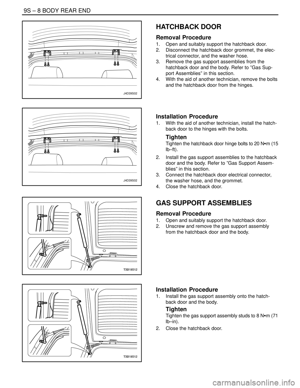
HATCHBACK DOOR
Removal Procedure
1. Open and suitably support the hatchback door.
2. Disconnect the hatchback door grommet, the elec-
trical connector, and the washer hose.
3. Remove the gas support assemblies from the
hatchback door and the body. Refer to ”Gas Sup-
port Assemblies” in this section.
4. With the aid of another technician, remove the bolts
and the hatchback door from the hinges.
J4D39S02
Installation Procedure
1. With the aid of another technician, install the hatch-
back door to the hinges with the bolts.
Tighten
Tighten the hatchback door hinge bolts to 20 NSm (15
lb–ft).
2. Install the gas support assemblies to the hatchback
door and the body. Refer to ”Gas Support Assem-
blies” in this section.
3. Connect the hatchback door electrical connector,
the washer hose, and the grommet.
4. Close the hatchback door.
GAS SUPPORT ASSEMBLIES
Removal Procedure
1. Open and suitably support the hatchback door.
2. Unscrew and remove the gas support assembly
from the hatchback door and the body.
Installation Procedure
1. Install the gas support assembly onto the hatch-
back door and the body.
Tighten
Tighten the gas support assembly studs to 8 NSm (71
lb–in).
2. Close the hatchback door.
Page 2481 of 2643
9S – 10IBODY REAR END
DAEWOO V–121 BL4
GENERAL DESCRIPTION
AND SYSTEM OPERATION
FUEL FILLER DOOR
The fuel filler door attaches to the fuel tank pocket on the
right side of the vehicle. The door is opened by pulling on
the fuel filler door remote handle located on the floor in
front of the driver’s seat.
REAR DECK LID (NOTCHBACK)
The rear deck lid consists of an inner and outer panel thatis hemmed around the perimeter and bonded together
with structural adhesive. The deck lid torque rods assist in
the opening of the rear deck lid and hold it in the open posi-
tion.
HATCHBACK DOOR
The Hatchback door consists of the rear hatch glass within
a steel frame. The steel frame is made of an inner and an
outer panel hemmed around the perimeter, and bonded
together with structural adhesive. The gas support assem-
blies assist in the opening of the hatchback door, and can
hold the door open.
Page 2507 of 2643

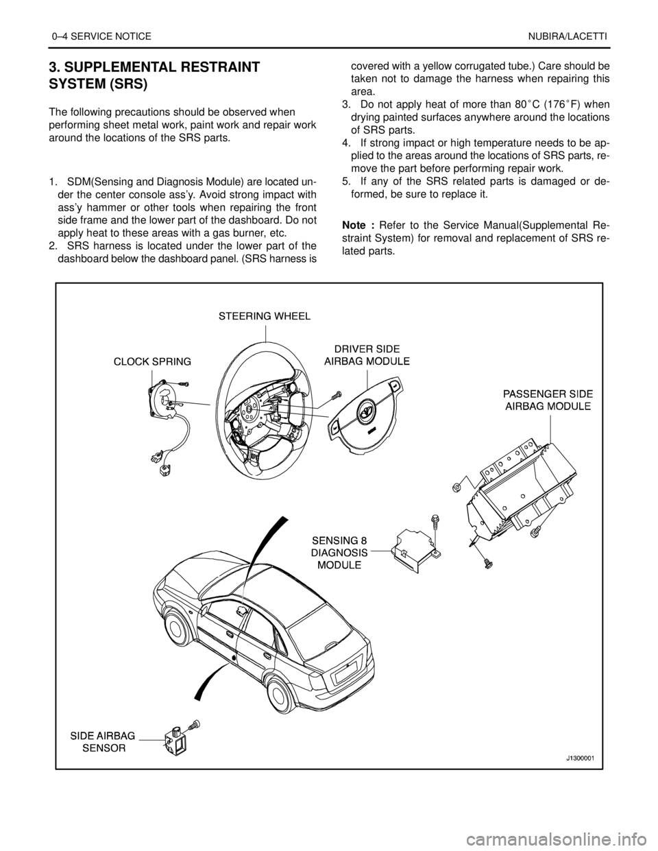
0–4 SERVICE NOTICENUBIRA/LACETTI
3. SUPPLEMENTAL RESTRAINT
SYSTEM (SRS)
.
The following precautions should be observed when
performing sheet metal work, paint work and repair work
around the locations of the SRS parts.
.
1. SDM(Sensing and Diagnosis Module) are located un-
der the center console ass’y. Avoid strong impact with
ass’y hammer or other tools when repairing the front
side frame and the lower part of the dashboard. Do not
apply heat to these areas with a gas burner, etc.
2. SRS harness is located under the lower part of the
dashboard below the dashboard panel. (SRS harness iscovered with a yellow corrugated tube.) Care should be
taken not to damage the harness when repairing this
area.
3. Do not apply heat of more than 80°C (176°F) when
drying painted surfaces anywhere around the locations
of SRS parts.
4. If strong impact or high temperature needs to be ap-
plied to the areas around the locations of SRS parts, re-
move the part before performing repair work.
5. If any of the SRS related parts is damaged or de-
formed, be sure to replace it.
.
Note : Refer to the Service Manual(Supplemental Re-
straint System) for removal and replacement of SRS re-
lated parts.
Page 2510 of 2643

1–2 GENERAL INFORMATIONNUBIRA/LACETTI
1. GENERAL INSTRUCTION
This publication is designed to help you the body repair
technician with your specialized work. Vehicle bodywork
has changed a great deal over the years. As vehicles
have developed technically, vehicle bodywork has also
had to meet new requirements with design, changes to
reconcile apparently conflicting demands to name just a
few examples:
S strength and safety ; low weight
S spaciousness ; good aerodynamices
S high quality ; low price
.
The durability and ease of repair of the bodywork also
plays an important part.
.
Nowadays, the use of highly automated production
equipment makes it possible to maintain the tightest
tolerances and thus ensure a high level of quality.
.
When bodywork is damaged, the customer rightly ex-
pects it to be expertly repaired to the same quality stan-
dards.
.
At the same time, for his safety, the customer expects
you to have comprehensive knowledge of materials,
measuring and straightening methods, possible distor-
tion, optimum corrosion prevention and much more be-
sides.
.
This publication is designed to help you update your
knowledge and give you an idea of what you require to
rectify moderate or severe accident damage, for your
own safety and for the satisfaction of your customers.
2. IMPORTANT SAFETY NOTICE
2–1. BEFORE BEGINNING WORK
S Disconnect the battery to reduce the possibility of fire
caused by electrical shorts.
S Check for fuel leaks and repair as necessary.
S Remove the fuel tank and/or fuel lines if welding equip-
ment is to be used near the fuel system.
S Before welding, sanding or cutting, protect carpets and
seats with fire–proof covers.
S Follow standard safety practices when using toxic or
flammable liquids.
S Use standard safety equipment when spraying paint,
welding, cutting, sanding or grinding. Standard safety
equipment includes.
S Respirator and filter masks: Designed to filter out toxic
fumes, mist, dust or other airborn particles. Use a respi-
rator or filter mask designed to protect you from the haz-
ards of the particular job; some respirators, for example,
are designed to filter out only dust and airborn particles,
not toxic fumes.
S Safety goggles or glasses: Designed to protect your
eyes from projectiles, dust particles or splashing liquid.
S Gloves: Rubber gloves protect against corrosive chemi-
cals. Welding gloves protect against burns and abra-
sions caused by welding, sanding or grinding.
S Safety shoes: Non–slip soles protect against slipping.
Metal toe inserts protect against falling objects.
S Ear plugs: Protect eardrums from harmful noise levels.
.
2–2. DURING WORK
S Do not smoke while working near the fuel system.
S Deposit gas or solvent–soaked shop towels in an ap-
proved container.
S Brake lining contains asbestos, which can cause cancer.
Do not use an air hose to blow off brake assemblies: use
only an approved vacuum cleaner, and wear an ap-
proved filter mask or respirator.
S Always attach a safety cable when using a hydraulic ram
or a frame straightening table: do not stand in direct line
with the chains used on such equipment.
Page 2520 of 2643

1–12 GENERAL INFORMATIONNUBIRA/LACETTI
10. BODY REPAIR PROCEDURES
No.OperationProcedureRemarks
1InspectionInspect the damaged parts and the extent of damage and make
plans for the repair..
2PreparationPrepare the new parts, special repair tools and others..
3RemovalRemove the related parts for repair..
4Pull outRoughly pull out and straighten the damaged areas..
5Cut and pry offCut off the damaged areas and drills on the spot weld nuggets
and pry off the remaining spot weld flanges..
6Peel offPeel off the undercoat and sealer..
7MoldingMold damaged areas and even out the welding flanges and fill
any holes..
8Set the new partsGrind both sides of the welding section and set the new parts
and tack welds for temporary installation..
9InspectionInspect the dimensions for correct position and preinstall the ex-
terior parts and check the clearances and level differences..
10WeldingPerform a trial welding and the main welding..
11FinishFinish the welding areas and even out the flanges for a close fit..
12SealingApply the sealer to the matching and over lapped surface..
13UndercoatingApply the undercoat to the required areas..
14PaintingApply the paint..
15DeadnerApply the deadner to the designated areas..
16Anti–rust agentsCoating the anti–rust agents to the designated areas..
17InstallationInstall the related parts and rub in grease to the moving parts and
replenish the cooling liquid, oil, aircon gas and others..
18Check and adjustCheck all operations, wheel alignments, leaks, head lamp aim
and others with the specified check sheet..
Page 2527 of 2643

NUBIRA/LACETTIWELDING AND TOOLS 3–1
SECTION 3
WELDING AND TOOLS
CONTENTS
1. SPOT WELDING 3 – 2. . . . . . . . . . . . . . . . . . . . . . . . . . . . . . . . . . . . . . . . . . . . . . . . . . .
1.1.GENERAL DESCRIPTION3–2 . . . . . . . . . . . . . . . . . . . . . . . . . . . . . . . . . . . . . . . . . . . . . . . . . . . . . . . . . . . . . . . . . . . . . .
1.2.WELDING CONDITIONS3–2 . . . . . . . . . . . . . . . . . . . . . . . . . . . . . . . . . . . . . . . . . . . . . . . . . . . . . . . . . . . . . . . . . . . . . . . .
1.3.WELDING STRENGTH TEST3–3 . . . . . . . . . . . . . . . . . . . . . . . . . . . . . . . . . . . . . . . . . . . . . . . . . . . . . . . . . . . . . . . . . . . .
2. GAS WELDING 3 – 4. . . . . . . . . . . . . . . . . . . . . . . . . . . . . . . . . . . . . . . . . . . . . . . . . . . .
3. CARBON DIOXIDE ARC WELDER(MIG ARC WELDING) 3 – 5. . . . . . . . . . . . . . .
4. REPAIR TOOLS 3 – 6. . . . . . . . . . . . . . . . . . . . . . . . . . . . . . . . . . . . . . . . . . . . . . . . . . . .
Page 2530 of 2643

3–4 WELDING AND TOOLSNUBIRA/LACETTI
Note : It is difficult to perform spot welding in the following
circumstances.
S When it is not possible to remove any rust or paint at-
tached to the welding surfaces.
S When the tip of the spot welder cannot be inserted into
the welding section.
S When the welding surfaces can be seen from the outside
and welding will impair the exterior appearance.
.
In all these cases, it is recommended that the gas weld-
ing method be employed. However, if it is not possible
to perform spot welding because of space restrictions,
plug welding based on the arc welding method may be
performed instead. Here the welding sections must be
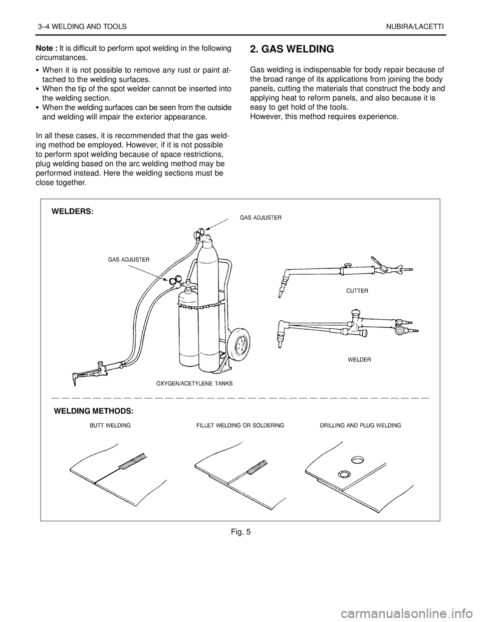
close together.2. GAS WELDING
.
Gas welding is indispensable for body repair because of
the broad range of its applications from joining the body
panels, cutting the materials that construct the body and
applying heat to reform panels, and also because it is
easy to get hold of the tools.
However, this method requires experience.
Fig. 5
Page 2531 of 2643
NUBIRA/LACETTIWELDING AND TOOLS 3–5
Note : Below is an example of how not to perform gas
welding, avoid operations like this.
Fig. 6
3. CARBON DIOXIDE ARC WELDER(MIG
ARC WELDING)
This welding process uses inexpensive carbon dioxide
instead of expensive inert gases as a shielding means.
Consumable metal electrodes are employed. It has a
wide range of applications, including butt welding of thin
plate, fillet welding, plug welding, and MIG spot welding.
In terms of the weld strength, it is also highly stable.
Fig. 7