2004 DAEWOO NUBIRA hood open
[x] Cancel search: hood openPage 2465 of 2643
9R – 4IBODY FRONT END
DAEWOO V–121 BL4
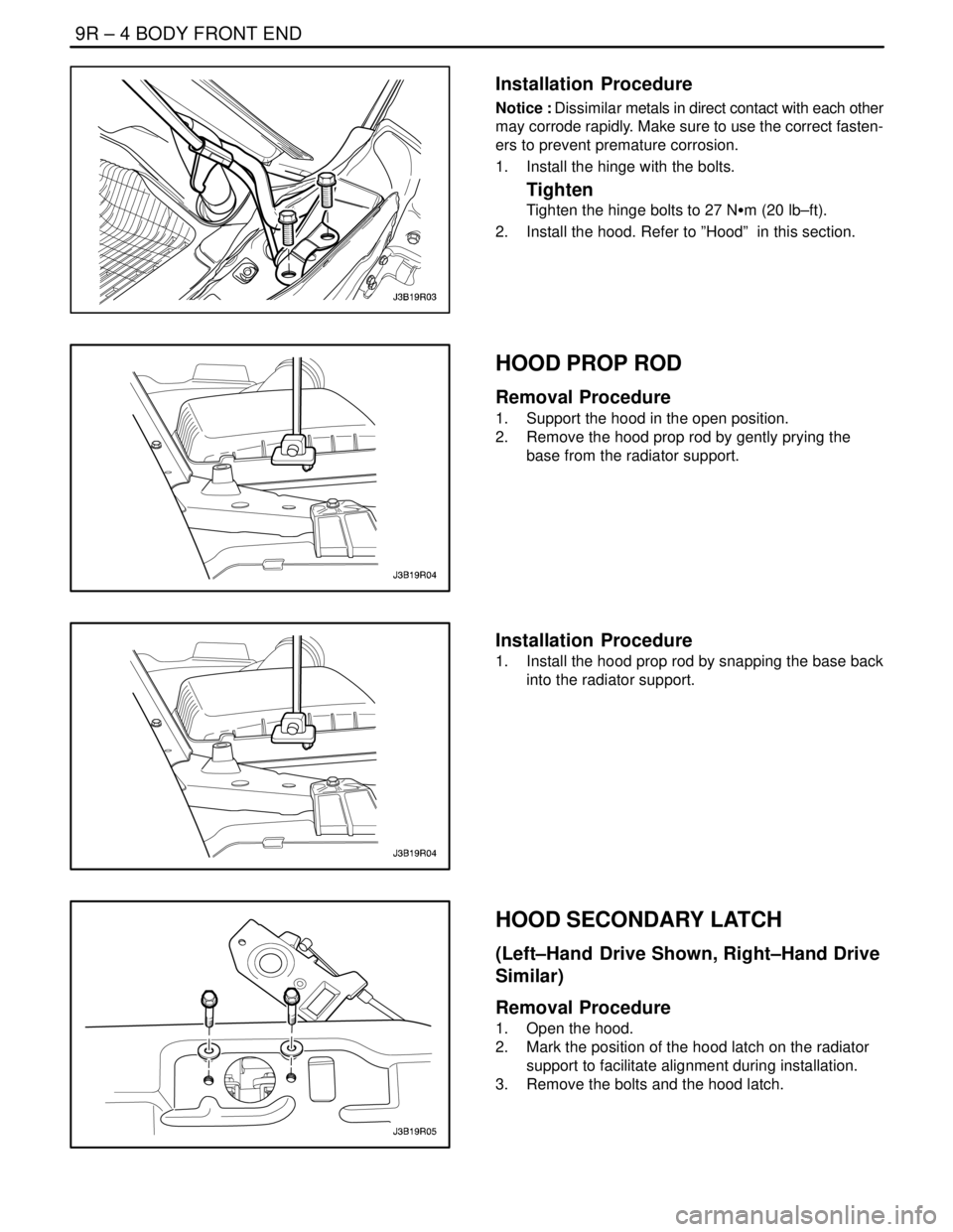
Installation Procedure
Notice : Dissimilar metals in direct contact with each other
may corrode rapidly. Make sure to use the correct fasten-
ers to prevent premature corrosion.
1. Install the hinge with the bolts.
Tighten
Tighten the hinge bolts to 27 NSm (20 lb–ft).
2. Install the hood. Refer to ”Hood” in this section.
HOOD PROP ROD
Removal Procedure
1. Support the hood in the open position.
2. Remove the hood prop rod by gently prying the
base from the radiator support.
Installation Procedure
1. Install the hood prop rod by snapping the base back
into the radiator support.
HOOD SECONDARY LATCH
(Left–Hand Drive Shown, Right–Hand Drive
Similar)
Removal Procedure
1. Open the hood.
2. Mark the position of the hood latch on the radiator
support to facilitate alignment during installation.
3. Remove the bolts and the hood latch.
Page 2466 of 2643
BODY FRONT END 9R – 5
DAEWOO V–121 BL4
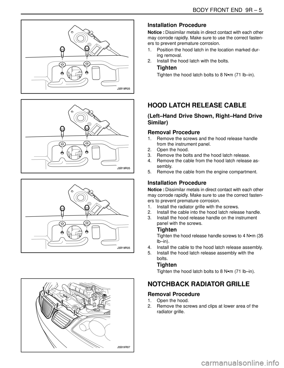
Installation Procedure
Notice : Dissimilar metals in direct contact with each other
may corrode rapidly. Make sure to use the correct fasten-
ers to prevent premature corrosion.
1. Position the hood latch in the location marked dur-
ing removal.
2. Install the hood latch with the bolts.
Tighten
Tighten the hood latch bolts to 8 NSm (71 lb–in).
HOOD LATCH RELEASE CABLE
(Left–Hand Drive Shown, Right–Hand Drive
Similar)
Removal Procedure
1. Remove the screws and the hood release handle
from the instrument panel.
2. Open the hood.
3. Remove the bolts and the hood latch release.
4. Remove the cable from the hood latch release as-
sembly.
5. Remove the cable from the engine compartment.
Installation Procedure
Notice : Dissimilar metals in direct contact with each other
may corrode rapidly. Make sure to use the correct fasten-
ers to prevent premature corrosion.
1. Install the radiator grille with the screws.
2. Install the cable into the hood latch release handle.
3. Install the hood release handle on the instrument
panel with the screws.
Tighten
Tighten the hood release handle screws to 4 NSm (35
lb–in).
4. Install the cable to the hood latch release assembly.
5. Install the hood latch release assembly with the
bolts.
Tighten
Tighten the hood latch bolts to 8 NSm (71 lb–in).
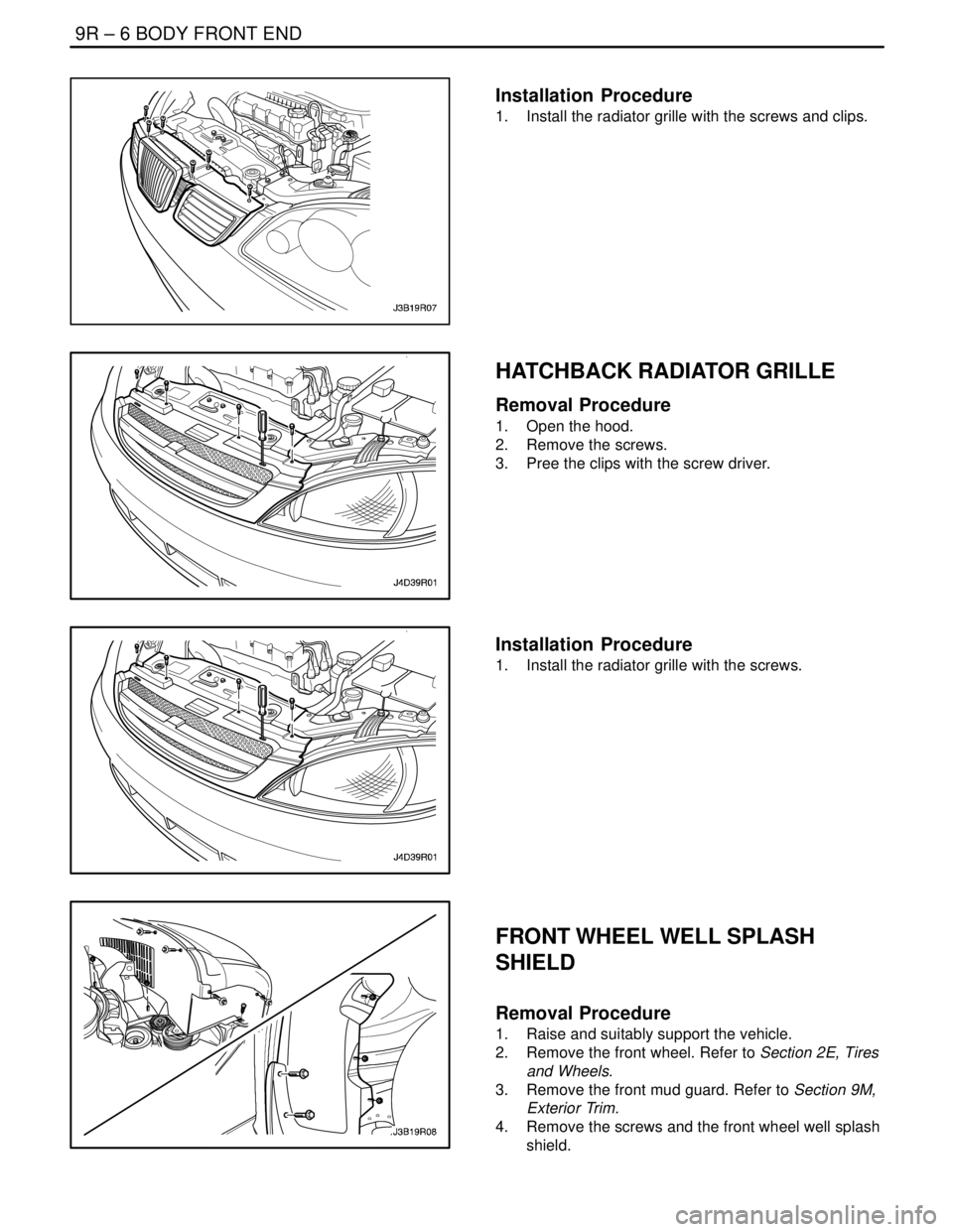
NOTCHBACK RADIATOR GRILLE
Removal Procedure
1. Open the hood.
2. Remove the screws and clips at lower area of the
radiator grille.
Page 2467 of 2643
9R – 6IBODY FRONT END
DAEWOO V–121 BL4
Installation Procedure
1. Install the radiator grille with the screws and clips.
HATCHBACK RADIATOR GRILLE
Removal Procedure
1. Open the hood.
2. Remove the screws.
3. Pree the clips with the screw driver.
Installation Procedure
1. Install the radiator grille with the screws.
FRONT WHEEL WELL SPLASH
SHIELD
Removal Procedure
1. Raise and suitably support the vehicle.
2. Remove the front wheel. Refer to Section 2E, Tires
and Wheels.
3. Remove the front mud guard. Refer to Section 9M,
Exterior Trim.
4. Remove the screws and the front wheel well splash
shield.
Page 2485 of 2643

9T1 – 4IREMOTE KEYLESS ENTRY AND ANTI–THEFT SYSTEM
DAEWOO V–121 BL4
CONTROL MODULE/RECEIVER CONNECTOR
TerminalColorDescription
1YELSiren
2BLKGround
3––
4LT BLUDoor and Trunk Tamper Switch
5PNK/BLKTrunk Open Switch
6––
7PNK/DKBLUHood Open Switch
8PPLDoor contact Switch
9LT BLU/BLKUnlock
10LT GRN/WHTLock
11YELUnlock
12LT GRNAnti–Theft Door Locking Switch
13DK BLURight Turn Signal Bulb
14––
15PNKIgnition+
16––
17LT GRNDiagnostic Communication
18LT GRN/REDKey Reminder Switch
19YEL/DK GRNSecurity Indicator
20PPLAnti–Theft Door Locking Switch
21––
22––
23––
24BRNTrunk Open Switch
25ORNBattery+
26LT BLULeft Turn Signal Bulb
Page 2489 of 2643

9T1 – 8IREMOTE KEYLESS ENTRY AND ANTI–THEFT SYSTEM
DAEWOO V–121 BL4
GENERAL DESCRIPTION
AND SYSTEM OPERATION
REMOTE KEYLESS ENTRY AND
ANTI–THEFT SYSTEM
The remote keyless entry and anti–theft system can per-
form the following functions:
S Remotely lock and unlock the vehicle doors by
means of a hand–held, high–frequency transmitter.
S Sense intrusion into the vehicle.
S Activate a warning in the event of an intrusion.
S Help the driver find the vehicle in a parking area.
S Automatically re–lock the doors if the door or the
trunk is not opened within 30 seconds after the ve-
hicle has been unlocked by the remote keyless
entry.
S Communicate serial data to a scan tool to help
diagnose system faults.
The remote keyless entry and anti–theft system consists
of the following components:
S Keyless entry and anti–theft control module/receiv-
er.
S Security indicator.
S Trunk open switch (NOTCHBACK).
S Trunk tamper switch (NOTCHBACK).
S Front door tamper switches.
S Door contact switches.
S Central door lock relay.
S Turn signal bulbs.
S Siren.
S Hood open switch.
REMOTE LOCKING AND UNLOCKING
The hand–held transmitter locks and unlocks the vehicle
doors by sending radio waves to the control module/re-
ceiver in the vehicle. The effective range of the transmitter
varies between 5 and 10 meters, (approximately 16 to 32
feet), depending on whether or not objects, such as other
vehicles are blocking the path of the radio waves.
The transmitter has a LOCK button and an UNLOCK but-
ton which only function when the ignition is OFF. Pressing
the UNLOCK button has the following effects:
S The doors are unlocked.
S The turn signal bulbs flash twice.
S The control module is disarmed.
Pressing the LOCK button has the following effects:
S The doors are locked.
S The turn signal bulbs flash once.
S The control module is armed.
The transmitter has a replaceable battery. The battery is
designed to last at least two years before replacement is
necessary.
SECURITY INDICATOR
There is a security indicator on the instrument panel. After
the LOCK button of the transmitter is pressed, the module
is placed in the armed mode, and the security indicator
flashes. The security indicator turns ON for 0.1 second
and OFF for 0.7 second. It then flashes at that frequency
until the control module/receiver is disarmed.
INTRUSION SENSING
The anti–theft function is armed if the transmitter sends
the LOCK message to the control module/receiver when
the ignition is OFF. When the hood, door, or trunk is
opened, the hood open, door contact, or trunk open switch
sends a ”ground” signal to the control module/receiver.
Unless the control module/receiver is disarmed, the siren
will be activated when the ”ground” signal is received from
the trunk open, hood open, or door contact switches.
The following actions disarm the anti–theft system:
S An UNLOCK message is received from the trans-
mitter.
S Key operation is detected by the tamper switches.
(The tamper switches are operated by the lock cyl-
inders in the front doors and trunk.)
The alarm will also be activated if the control module/re-
ceiver detects voltage from the ignition before either of the
following conditions occur:
S An UNLOCK message is received from the trans-
mitter.
S Key operation is indicated by the tamper switches.
SIREN (GENERAL ONLY)
The remote keyless entry system is armed when the
LOCK message is received from the transmitter when the
ignition is OFF. When the system is armed, it will activate
the siren and flash the turn signals for 28 seconds if any
of the following conditions occur:
S Close all the windows.
S Turn the ignition key to LOCK and remove the key.
S Have all passengers get out of the vehicle.
S Close all doors, the hood and the turnk lid.
S The control module/receiver detects ignition voltage
while the system is armed.
The siren will not operate if any of the following conditions
occur after the system has been armed:
S The door is opened with the key.
S The trunk is opened with the key.
S The UNLOCK or LOCK button on the remote trans-
mitter is pressed within 2 seconds after the siren is
activated.
VEHICLE LOCATOR
The remote keyless entry system assists the driver in lo-
cating the vehicle. When the vehicle is unlocked with the
remote control, the turn signals flash twice to indicate the
location of the vehicle. The duration of the flashes and the
Page 2490 of 2643

REMOTE KEYLESS ENTRY AND ANTI–THEFT SYSTEM 9T1 – 9
DAEWOO V–121 BL4
length of time between flashes is used to indicate certain
vehicle conditions. Refer to ”Fault or Alarm Indication” in
this section.
AUTOLOCKING (SAFETY LOCK)
The remote keyless entry system features an autolocking
feature. If the doors are unlocked with the remote transmit-
ter when the control module/receiver is in the armed
mode, the doors are automatically re–locked after 30 sec-
onds unless any of the following events occur:
S A door is opened.
S The ignition is ON.
S The trunk is opened.
S The hood is opened.
CONTROL MODULE/RECEIVER
The remote keyless entry control module/receiver is con-
tained in the floor console. The module/receiver pro-
cesses signals from the remote transmitter and various
switches. It activates the alarm if an intrusion is detected.
The control module/receiver also has a self–diagnostic
function which will display trouble codes. In order to dis-
play trouble codes, a scan tool must be connected to the
data link connector (DLC).
The control module/receiver will not communicate with
transmitters from other vehicles because there are over
four billion possible electronic password combinations. Itis highly unlikely that any transmitters will use the same
password. The control module/receiver has an attached
antenna to detect signals from the transmitter.
FAULT OR ALARM INDICATION
When the UNLOCK button on the remote transmitter is
pressed, the control module/receiver will flash the parking
lights to indicate information about the remote keyless
entry and anti–theft system.
Normal Condition: If there has not been an intrusion, and
no fault has been detected, the control module/receiver
will signal a normal condition when the UNLOCK button is
pressed. The parking lights will flash twice for 0.5 second,
with a 0.5 second pause between flashes.
Fault Indication: If there is a fault in the remote keyless
entry and anti–theft system, the control module/receiver
will signal the fault when the UNLOCK button is pressed.
The parking lights will flash twice for 1 second, with a 0.5
second pause between flashes.
Alarm Indication: If there has been an intrusion since the
last time the LOCK button was pressed, the control mod-
ule/receiver will signal that there has been an intrusion
when the UNLOCK button is pressed. The parking lights
will flash twice for 0.5 second, with a 1.5 second pause be-
tween flashes.
Alarm and fault information will be erased the next time the
transmitter arms the control module/receiver by transmit-
ting a LOCK message.
Page 2537 of 2643
NUBIRA/LACETTIFRONT 4–3
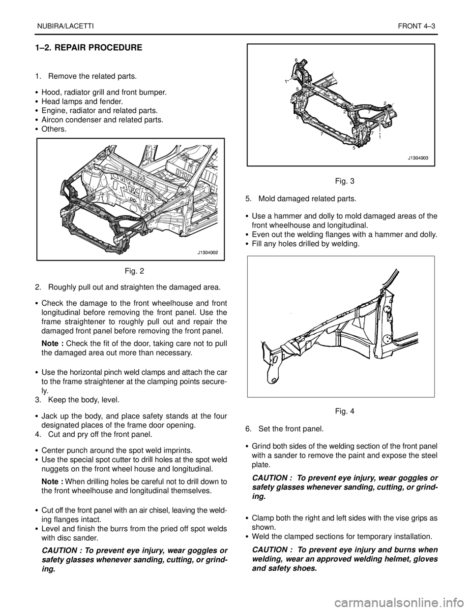
1–2. REPAIR PROCEDURE
1. Remove the related parts.
S Hood, radiator grill and front bumper.
S Head lamps and fender.
S Engine, radiator and related parts.
S Aircon condenser and related parts.
S Others.
Fig. 2
2. Roughly pull out and straighten the damaged area.
S Check the damage to the front wheelhouse and front
longitudinal before removing the front panel. Use the
frame straightener to roughly pull out and repair the
damaged front panel before removing the front panel.
Note : Check the fit of the door, taking care not to pull
the damaged area out more than necessary.
S Use the horizontal pinch weld clamps and attach the car
to the frame straightener at the clamping points secure-
ly.
3. Keep the body, level.
S Jack up the body, and place safety stands at the four
designated places of the frame door opening.
4. Cut and pry off the front panel.
S Center punch around the spot weld imprints.
S Use the special spot cutter to drill holes at the spot weld
nuggets on the front wheel house and longitudinal.
Note : When drilling holes be careful not to drill down to
the front wheelhouse and longitudinal themselves.
S Cut off the front panel with an air chisel, leaving the weld-
ing flanges intact.
S Level and finish the burrs from the pried off spot welds
with disc sander.
CAUTION : To prevent eye injury, wear goggles or
safety glasses whenever sanding, cutting, or grind-
ing.
Fig. 3
5. Mold damaged related parts.
S Use a hammer and dolly to mold damaged areas of the
front wheelhouse and longitudinal.
S Even out the welding flanges with a hammer and dolly.
S Fill any holes drilled by welding.
Fig. 4
6. Set the front panel.
S Grind both sides of the welding section of the front panel
with a sander to remove the paint and expose the steel
plate.
CAUTION : To prevent eye injury, wear goggles or
safety glasses whenever sanding, cutting, or grind-
ing.
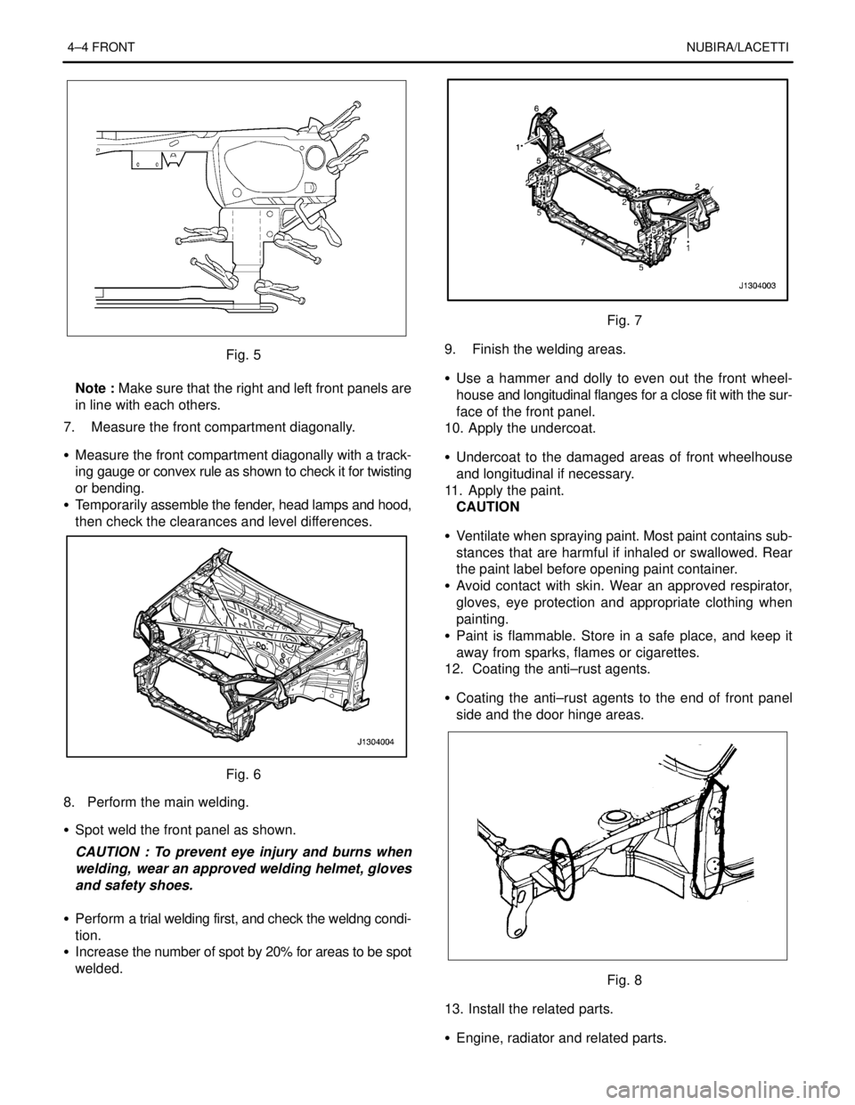
S Clamp both the right and left sides with the vise grips as
shown.
S Weld the clamped sections for temporary installation.
CAUTION : To prevent eye injury and burns when
welding, wear an approved welding helmet, gloves
and safety shoes.
Page 2538 of 2643
4–4 FRONTNUBIRA/LACETTI
Fig. 5
Note : Make sure that the right and left front panels are
in line with each others.
7. Measure the front compartment diagonally.
S Measure the front compartment diagonally with a track-
ing gauge or convex rule as shown to check it for twisting
or bending.
S Temporarily assemble the fender, head lamps and hood,
then check the clearances and level differences.
Fig. 6
8. Perform the main welding.
S Spot weld the front panel as shown.
CAUTION : To prevent eye injury and burns when
welding, wear an approved welding helmet, gloves
and safety shoes.
S Perform a trial welding first, and check the weldng condi-
tion.
S Increase the number of spot by 20% for areas to be spot
welded.
Fig. 7
9. Finish the welding areas.
S Use a hammer and dolly to even out the front wheel-
house and longitudinal flanges for a close fit with the sur-
face of the front panel.
10. Apply the undercoat.
S Undercoat to the damaged areas of front wheelhouse
and longitudinal if necessary.
11. Apply the paint.
CAUTION
S Ventilate when spraying paint. Most paint contains sub-
stances that are harmful if inhaled or swallowed. Rear
the paint label before opening paint container.
S Avoid contact with skin. Wear an approved respirator,
gloves, eye protection and appropriate clothing when
painting.
S Paint is flammable. Store in a safe place, and keep it
away from sparks, flames or cigarettes.
12. Coating the anti–rust agents.
S Coating the anti–rust agents to the end of front panel
side and the door hinge areas.
Fig. 8
13. Install the related parts.
S Engine, radiator and related parts.