2004 DAEWOO LACETTI engine oil API
[x] Cancel search: engine oil APIPage 16 of 2643
GENERAL INFORMATION 0B – 9
DAEWOO V–121 BL4
MAINTENANCE AND REPAIR
MAINTENANCE AND LUBRICATION
NORMAL VEHICLE USE
The maintenance instructions contained in the mainte-
nance schedule are based on the assumption that the ve-
hicle will be used for the following reasons:
S To carry passengers and cargo within the limitation
indicated on the tire placard located on the edge of
the driver’s door.
S To be driven on reasonable road surfaces and with-
in legal operating limits.
EXPLANATION OF SCHEDULED
MAINTENANCE SERVICES
The services listed in the maintenance schedule are fur-
ther explained below. When the following maintenance
services are performed, make sure all the parts are re-
placed and all the necessary repairs are done before driv-
ing the vehicle. Always use the proper fluid and lubricants.
Drive Belt Inspection
When a separate belt drives the power steering pump, the
air conditioning compressor and the generator, inspect it
for cracks, fraying, wear and proper tension. Adjust or re-
place the belt as needed.
Engine Oil and Oil Filter Change
API Classifications of Engine Oil
The International Lubricant Standardization and Approval
Committee (ILSAC) and American Petroleum Institute
classifies engine oils according to their performance quali-
ty. Always use oil rated API–SL (ILSAC GF–III) or better.
Engine Oil Viscosity
Engine oil viscosity (thickness) has an effect on fuel econ-
omy and cold weather operation. Lower viscosity engine
oils can provide better fuel economy and cold weather per-
formance; however, higher temperature weather condi-
tions require higher viscosity engine oils for satisfactory lu-
brication. Using oils of any viscosity other than those
viscosities recommended could result in engine damage.
Cooling System Service
Drain, flush and refill the system with new coolant. Refer
to ”Recommended Fluids And Lubricants” in this section.
Fuel Micro–Filter Replacement
Replace the engine fuel filter every 45,000 km (27,000
miles).
Air Cleaner Element Replacement
Replace the air cleaner element every 45,000 km (27,000
miles).Replace the air cleaner more often under dusty conditions.
Throttle Body Mounting Bolt Torque
Check the torque of the mounting bolts.
Tighten the throttle body mounting bolts to 15 NSm (11 lb–
ft) if necessary.
Spark Plug Replacement
Replace spark plugs with the same type.
Spark Plug Wire Replacement
Clean wires and inspect them for burns, cracks or other
damage. Check the wire boot fit at the DIS module and at
the spark plugs. Replace the wires as needed.
Brake System Service
Check the disc brake pads and the drum brake linings ev-
ery 15,000 km (9,000 miles) or 12 months. Check the pad
and the lining thickness carefully. If the pads or the linings
are not expected to last to the next scheduledmaintenance
service, replace the pads or the linings. Check the breath-
er hole in the brake fluid reservoir cap to be sure it is free
from dirt and the passage is open.
Transaxle Service
The manual transaxle fluid does not require changing. For
automatic transaxles, refer to ”Scheduled Maintenance
Charts” in this section.
Tire and Wheel Inspection and Rotation
Check the tires for abnormal wear or damage. To equalize
wear and obtain maximum tire life, rotate the tires. If irreg-
ular or premature wear exists, check the wheel alignment
and check for damaged wheels. While the tires and
wheels are removed, inspect the brakes. Refer to ”Each
Time The Oil Is Changed” in this section.
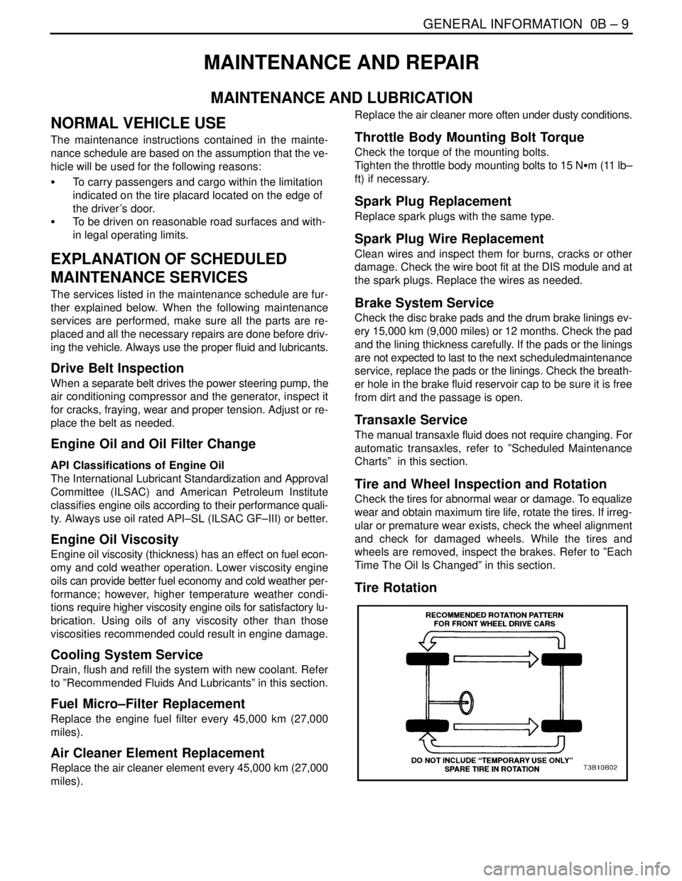
Tire Rotation
Page 21 of 2643

0B – 14IGENERAL INFORMATION
DAEWOO V–121 BL4
Engine Cooling System
Inspect the coolant and freeze protection fluid. If the fluid
is dirty or rusty, drain, flush and refill the engine cooling
system with new coolant. Keep the coolant at the proper
mixture in order to ensure proper freeze protection, corro-sion protection and engine operating temperature. Inspect
the hoses. Replace the cracked, swollen, or deteriorated
hoses. Tighten the clamps. Clean the outside of the radia-
tor and the air conditioning condenser. Wash the filler cap
and the neck. Pressure test the cooling system and the
cap in order to help ensure proper operation.
RECOMMENDED FLUIDS AND LUBRICANTS
UsageCapacityFluid/Lubricant
Engine Oil3.75L (4.0 qt) : 1.4L DOHC
3.75L (4.0 qt) : 1.6L DOHC
4.0L (4.2 qt) : 1.8L DOHCAPI SL (ILSAC GF–III) grade or better
SAE 5W–30, SAE10W–30, SAE15W–40
(Cold area : SAE5W–30
Hot area : SAE 15W–40)
Engine Coolant7.0L (7.49 qt) : 1.4L DOHC
7.2L (7.6 qt) : 1.6L DOHC
7.4L (7.8 qt) : 1.8L DOHCMixture of water and good quality ethylene gly-
col base antifreeze (year–round coolant)
Brake Fluid and Clutch Fluid0.5L (0.5 qt)DOT–3 or DOT–4
Power Steering System1.1L (1.2 qt)DEXRON®–III or DEXRON®–IID
Automatic Transaxle5.77 ± 0.2L (6.1 ± 0.2 qts) :
1.6L DOHC (AISIN 81–40LE)ESSO JWS 3309 or ISU DEXRON III
6.9 ± 0.2L (7.3 ± 0.2 qts) :
1.8L DOHC (ZF 4HP16)ESSO LT 71141 or TOTAL ATF H50235
Manual Transaxle1.8L (2.0 qt)Manual Transaxle Fluid
SAE80W (Cold Area : SAE 75W)
Manual Transaxle Shift LinkageAs requiredMultipurpose type grease meeting require-
ments NLGI No. 1 or 2
Key Lock CylindersAs requiredSilicone lubricant
Automatic Transaxle Shift Link-
ageAs requiredEngine oil
Clutch Linkage Pivot PointsAs requiredEngine oil
Floor Shift Linkage PointsAs requiredEngine oil
Hood Latch Assembly
a. Pivots and Spring Anchor
b. Release PawlAs requireda. Engine oil
b. Multipurpose type grease meeting require-
ments NLGI No. 1 or 2
Hood and door hinges
Fuel door hinge
Rear compartment lid hingesAs requiredEngine oil
WeatherstripsAs requiredSilicone grease
Page 120 of 2643

1.4L/1.6L DOHC ENGINE MECHANICAL 1C1 – 77
DAEWOO V–121 BL4
GENERAL DESCRIPTION
AND SYSTEM OPERATION
CYLINDER HEAD AND GASKET
The cylinder head is made of an aluminum alloy. The cylin-
der head uses cross–flow intake and exhaust ports. A
spark plug is located in the center of each combustion
chamber. The cylinder head houses the dual camshafts.
CRANKSHAFT
The crankshaft has eight integral weights which are cast
with it for balancing. Oil holes run through the center of the
crankshaft to supply oil to the connecting rods, the bear-
ings, the pistons, and the other components. The end
thrust load is taken by the thrust washers installed at the
center journal.
TIMING BELT
The timing belt coordinates the crankshaft and the dual
overhead camshafts and keeps them synchronized. The
timing belt also turns the water pump. The timing belt and
the pulleys are toothed so that there is no slippage be-
tween them. There are two idler pulleys. An automatic ten-
sioner pulley maintains the timing belt’s correct tension.
The timing belt is made of a tough reinforced rubber similar
to that used on the serpentine accessory drive belt. The
timing belt requires no lubrication.
OIL PUMP
The oil pump draws engine oil from the oil pan and feeds
it under pressure to the various parts of the engine. An oil
strainer is mounted before the inlet of the oil pump to re-
move impurities which could clog or damage the oil pump
or other engine components. When the drive gear rotates,
the driven gear rotates. This causes the space between
the gears to constantly open and narrow, pulling oil in from
the oil pan when the space opens and pumping the oil out
to the engine as it narrows.
At high engine speeds, the oil pump supplies a much high-
er amount of oil than is required for lubrication of the en-
gine. The oil pressure regulator prevents too much oil from
entering the engine lubrication passages. During normal
oil supply, a coil spring and valve keep the bypass closed,
directing all of the oil pumped to the engine. When the
amount of oil being pumped increases, the pressure be-
comes high enough to overcome the force of the spring.This opens the valve of the oil pressure regulator, allowing
the excess oil to flow through the valve and drain back to
the oil pan.
OIL PAN
The engine oil pan is mounted to the bottom of the cylinder
block. The engine oil pan houses the crankcase and is
made of cast metal.
Engine oil is pumped from the oil pan by the oil pump. After
it passes through the oil filter, it is fed through two paths
to lubricate the cylinder block and the cylinder head. In one
path, the oil is pumped through the oil passages in the
crankshaft to the connecting rods, then to the pistons and
the cylinders. It then drains back to the oil pan. In the sec-
ond path, the oil is pumped through the oil passages to the
camshaft. The oil passes through the internal passage-
ways in the camshafts to lubricate the valve assemblies
before draining back to the oil pan.
EXHAUST MANIFOLD
A single four–port, rear–takedown manifold is used with
this engine. The manifold is designed to direct escaping
exhaust gases out of the combustion chambers with a
minimum of back pressure. The oxygen sensor is
mounted to the exhaust manifold.
INTAKE MANIFOLD
The intake manifold has four independent long ports and
uses inertial supercharging to improve engine torque at
low and moderate speeds. The plenum is attached to the
intake manifold.
CAMSHAFTS
This engine is a dual overhead camshaft (DOHC) type,
which means there are two camshafts. One camshaft op-
erates the intake valves, and the other camshaft operates
the exhaust valves. The camshafts sit in journals on the
top of the engine in the cylinder head and are held in place
by camshaft caps. The camshaft journals of the cylinder
head are drilled to create oil passages. Engine oil travels
to the camshafts under pressure where it lubricates each
camshaft journal. The oil returns to the oil pan through
drain holes in the cylinder head. The camshaft lobes are
machined into the solid camshaft to open and close the in-
take and the exhaust valves precisely the correct amount
at the correct time. The camshaft lobes are oiled by splash
action from pressurized oil escaping from the camshaft
journals.
Page 195 of 2643

1.8L DOHC ENGINE MECHANICAL 1C2 – 75
DAEWOO V–121 BL4
GENERAL DESCRIPTION
AND SYSTEM OPERATION
CYLINDER HEAD AND GASKET
The cylinder head is made of an aluminum alloy. The cylin-
der head uses cross–flow intake and exhaust ports. A
spark plug is located in the center of each combustion
chamber. The cylinder head houses the dual camshafts.
CRANKSHAFT
The crankshaft has eight integral weights which are cast
with it for balancing. Oil holes run through the center of the
crankshaft to supply oil to the connecting rods, the bear-
ings, the pistons, and the other components. The end
thrust load is taken by the thrust washers installed at the
center journal.
TIMING BELT
The timing belt coordinates the crankshaft and the dual
overhead camshafts and keeps them synchronized. The
timing belt also turns the coolant pump. The timing belt
and the pulleys are toothed so that there is no slippage be-
tween them. There are two idler pulleys. An automatic ten-
sioner pulley maintains the timing belt’s correct tension.
The timing belt is made of a tough reinforced rubber similar
to that used on the serpentine drive belt. The timing belt
requires no lubrication.
OIL PUMP
The oil pump draws engine oil from the oil pan and feeds
it under pressure to the various parts of the engine. An oil
strainer is mounted before the inlet of the oil pump to re-
move impurities which could clog or damage the oil pump
or other engine components. When the crankshaft ro-
tates, the oil pump driven gear rotates. This causes the
space between the gears to constantly open and narrow,
pulling oil in from the oil pan when the space opens and
pumping the oil out to the engine as it narrows.
At high engine speeds, the oil pump supplies a much high-
er amount of oil than required for lubrication of the engine.
The oil pressure regulator prevents too much oil from en-
tering the engine lubrication passages. During normal oil
supply, a coil spring and valve keep the bypass closed, di-
recting all of the oil pumped to the engine. When the
amount of oil being pumped increases, the pressure be-
comes high enough to overcome the force of the spring.This opens the valve of the oil pressure regulator, allowing
the excess oil to flow through the valve and drain back to
the oil pan.
OIL PAN
The engine oil pan is mounted to the bottom of the cylinder
block. The engine oil pan houses the crankcase and is
made of cast aluminum.
Engine oil is pumped from the oil pan by the oil pump. After
it passes through the oil filter, it is fed through two paths
to lubricate the cylinder block and cylinder head. In one
path, the oil is pumped through oil passages in the crank-
shaft to the connecting rods, then to the pistons and cylin-
ders. It then drains back to the oil pan. In the second path,
the oil is pumped through passages to the camshaft. The
oil passes through the internal passageways in the cam-
shafts to lubricate the valve assemblies before draining
back to the oil pan.
EXHAUST MANIFOLD
A single four–port, rear–takedown manifold is used with
this engine. The manifold is designed to direct escaping
exhaust gases out of the combustion chambers with a
minimum of back pressure. The oxygen sensor is
mounted to the exhaust manifold.
INTAKE MANIFOLD
The intake manifold has four independent long ports and
utilizes an inertial supercharging effect to improve engine
torque at low and moderate speeds.
CAMSHAFTS
This engine is a dual overhead camshaft (DOHC) type,
which means there are two camshafts. One camshaft op-
erates the intake valves, and the other camshaft operates
the exhaust valves. The camshafts sit in journals on the
top of the engine (in the cylinder head) and are held in
place by camshaft caps. The camshaft journals of the cyl-
inder head are drilled for oil passages. Engine oil travels
to the camshafts under pressure where it lubricates each
camshaft journal. The oil returns to the oil pan through
drain holes in the cylinder head. The camshaft lobes are
machined into the solid camshaft to precisely open and
close the intake and the exhaust valves the correct
amount at the correct time. The camshaft lobes are oiled
by splash action from pressurized oil escaping from the
camshaft journals.
Page 203 of 2643
1D – 8IENGINE COOLING
DAEWOO V–121 BL4
MAINTENANCE AND REPAIR
ON–VEHICLE SERVICE
DRAINING AND REFILLING THE
COOLING SYSTEM
CAUTION : Do not remove the surge tank cap while
the engine and the radiator are hot. Scalding fluid and
steam may be blown out under pressure.
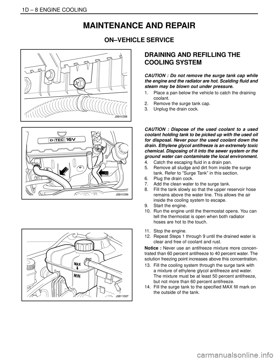
1. Place a pan below the vehicle to catch the draining
coolant.
2. Remove the surge tank cap.
3. Unplug the drain cock.
CAUTION : Dispose of the used coolant to a used
coolant holding tank to be picked up with the used oil
for disposal. Never pour the used coolant down the
drain. Ethylene glycol antifreeze is an extremely toxic
chemical. Disposing of it into the sewer system or the
ground water can contaminate the local environment.
4. Catch the escaping fluid in a drain pan.
5. Remove all sludge and dirt from inside the surge
tank. Refer to ”Surge Tank” in this section.
6. Plug the drain cock.
7. Add the clean water to the surge tank.
8. Fill the tank slowly so that the upper reservoir hose
remains above the water line. This allows the air
inside the cooling system to escape.
9. Start the engine.
10. Run the engine until the thermostat opens. You can
tell the thermostat is open when both radiator
hoses are hot to the touch.
11. Stop the engine.
12. Repeat Steps 1 through 9 until the drained water is
clear and free of coolant and rust.
Notice : Never use an antifreeze mixture more concen-
trated than 60 percent antifreeze to 40 percent water. The
solution freezing point increases above this concentration.
13. Fill the cooling system through the surge tank with
a mixture of ethylene glycol antifreeze and water.
The mixture must be at least 50 percent antifreeze,
but not more than 60 percent antifreeze.
14. Fill the surge tank to the specified MAX fill mark on
the outside of the tank.
Page 1405 of 2643

5A1 – 56IZF 4 HP 16 AUTOMATIC TRANSAXLE
DAEWOO V–121 BL4
SYMPTOM DIAGNOSIS
Oil Leakage
Notice :
– Careful localization of leakage points may make it
possible to prevent incorrect or cost–intensive re-
pairs.
Test Steps :– Thoroughly clean the transaxle, engine, and sur-
rounding area(using a steam jet, for example).
– To locate leakage, use a suitable identifying spray
or similar product.
– Depending on the amount of leakage, take the
car for a short or a longer test drive – It may prove
sufficient to place the car on a hoist and run the
engine at idle speed to trace the leak.
– If possible, determine exactly which type of oil is
escaping.
Symptom
Possible CauseAction
Transaxle Oil Leak-
ageOil Pump(Torque Converter Sealing)S Visually check torque converter sealing.
S Replace the converter sealing as described in
the transaxle repair on the vehicle service.
Crankshaft Sealing RingS Check whether engine oil or TFT is leaking out.
S If leak is engine oil, replace the sealing ring as
described in the engine repair instruction.
Torque ConverterS Visual check.
S Fit an exchange converter as described in the
repair instruction.
Oil Content Too HighS Check oil level(TFT and axle oil) as described
in this chapter.
S Correct oil level, and recheck after a test drive.
Notice : Comply with the measuring procedure (fill-
ing procedure) in the repair instruction. Check the oil
level at the overflow plug adjust to proper level if nec-
essary.
O–ring at Bolt Head Damaged or Miss-
ingS Check O–ring.
S Replace O–ring as described in the repair in-
struction.
Shaft SealS Visually check the shaft seal.
S Replace the sealing ring as described in the
repair instruction.
Hose Clamp LooseS Check to ensure that the hose clamp fits tightly.
S If necessary, retighten clamp.
Oil Pan Gasket Not Installed ProperlyS Check to see if the gasket was positioned
properly.
S Install gasket properly as described in the re-
pair instruction.
Oil Pan Gasket DamagedS Check the gasket visually.
S Replace gasket as described in the repair in-
struction.
Bolt at Bracket LooseCheck the Tightening Torque
Retighten bolt
Sealing Ring at Oil DipstickS Check O–ring.
S If necessary, replace O–ring.
Sealing Ring Near End–Cover Connec-
tion DefectiveS Check sealing rings.
S Put in new sealing ring Check O–ring as de-
scribed in the repair instruction.
Page 1407 of 2643

5A1 – 58IZF 4 HP 16 AUTOMATIC TRANSAXLE
DAEWOO V–121 BL4
Symptom ActionPossible Cause
NoiseThe Engine’s Torsional Vibrations are
Being Transmitted to the Drive ShaftsS At low speeds in fourth gear, vibration can
arise (driving at too low an engine speed)
S Noise is functionally unavoidable; due to toler-
ances. Convince the customer.
NoiseTorque Reaction Strut LooseS Check mounting and repair if necessary.
Shift quality
Notice :
– The assessment of shaft quality is, to a large ex-
tent, an individual, subjective matter. Take careful
note of how the customer describes the complaint
and of the manner in which he or she handles the
vehicle and the controls.
– A sudden deterioration of shift quality may also
be caused by the transaxle selecting an emergency
or substitute program
Test Steps :– Carry out the general checks described in the
automatic transaxle diagnostic information.
– Perform a test drive to answer the following ques-
tions.
In which driving situations does the shift quality
complaint arise?
To which shifts does the complaint apply?
Is the complaint reproducible within a short period,
or has it only occurred sporadically or on a single
occasion?
– Check the oil level and oil quality
– Interrogate the fault memory and read out mea-
surement block data.
Symptom
Possible CauseAction
Shift QualityRapid Pressure Build–up in the ClutchS Operating error (position selected several times
in quick succession).
Jerk When Parking Lock Is ReleasedS Refer to ”Noise” in this section.
Incorrect Electronic Transaxle Control
moduleS Check the data status for transaxle control
module ; refer to ”TCM” in this section.
Emergency/Substitute Program Has
Been ActivatedS For checking and remedial action, refer to
”Emergency/Substitute program” in this sec-
tion.
Accelerator Pedal in Indefinite Position
Between Full Throttle and Kick DownS Persuade customer to choose clearly between
kick down and full throttle
S Check setting according go engine repair in-
struction ; adjust if necessary.
Control Overlap Between to Clutches
During ShiftS Production status
S Convince the customer
Temperature Sensor
(Not Fault Memory)S Check function according to ”Emergency/Sub-
stitute program” in this section.
Kick Down Setting IncorrectS Check
A) Floor mat is obstructing accelerator pedal
B) The kick down setting as described in the
Engine Section.
Malfunction
Notice :
The faults dealt with here concern transaxle functions
such as ”traction” (forwards and reverse) and all type of
shifts. Entries will not always be made in the fault memory.Test Steps :
Perform the general checks according to the automatic
transaxle diagnostic procedure.
– Test drive
– Check oil level and quality
– Interrogate fault memory
Page 2053 of 2643

MANUAL CONTROL HEATING, VENTILATION AND AIR CONDITIONING SYSTEM 7B – 51
DAEWOO V–121 BL4
GENERAL DESCRIPTION
AND SYSTEM OPERATION
GENERAL INFORMATION
THE V5 A/C SYSTEM
The V5 variable displacement compressor along with the
thermal expansion valve on the evaporator, constitutes a
largely self–regulating system. There is no pressure cycl-
ing switch, no high–pressure cut–off switch and no low–
pressure cut–off switch. The compressor clutch is con-
trolled by the electronic control module (ECM), which
receives data from various engine systems and from a
pressure transducer located in the high–pressure refriger-
ant pipe. In normal operation, the clutch is engaged contin-
uously. Should one of the monitored conditions become
abnormal, the ECM will disengage the compressor clutch
until normal operation is restored. These conditions in-
clude the following:
S Wide–open throttle.
S High engine coolant temperature.
S High engine RPM.
S Refrigerant low pressure.
S Refrigerant high pressure.
The compressor clutch will remain disengaged until nor-
mal operation is established.
SYSTEM
COMPONENTS–FUNCTIONAL
Compressor
All compressors are belt–driven from the engine crank-
shaft through the compressor clutch pulley. The compres-
sor pulley rotates without driving the compressor shaft un-
til an electromagnetic clutch coil is energized. When
voltage is applied to energize the clutch coil, the clutch
plate and hub assembly is drawn rearward toward the
pulley. The magnetic force locks the clutch plate and
pulley together as one unit to drive the compressor shaft.
As the compressor shaft is driven, it compresses the low–
pressure refrigerant vapor from the evaporator into a
high–pressure, high–temperature vapor. The refrigerant
oil which is used to lubricate the compressor is carried with
the refrigerant. Refer to ”V5 Air Conditioning Compressor
Overhaul” in this section.
Condenser Core
The condenser assembly in front of the radiator consists
of coils which carry the refrigerant, and cooling fins that
provide the rapid transfer of heat. The air passing through
the condenser cools the high–pressure refrigerant vapor
and causes it to condense into a liquid.
Expansion Valve
The expansion valve is located with the evaporator core,
on the front passenger side fire wall.
The expansion valve can fail in three different positions:
open, closed, or restricted.
An expansion valve that fails in the open position will result
in a noisy A/C compressor or no cooling. The cause can
be a broken spring, a broken ball, or excessive moisture
in the A/C system. If the spring or the ball are found to be
defective, replace the expansion valve. If excessive mois-
ture is found in the A/C system, recycle the refrigerant.
An expansion valve that fails in the closed position will re-
sult in low suction pressure and no cooling. This may be
caused by a failed power dome or excessive moisture in
the A/C system. If the power dome on the expansion valve
is found to be defective, replace the expansion valve. If ex-
cessive moisture is found in the A/C system, recycle the
refrigerant.
A restricted expansion valve will result in low suction pres-
sure and no cooling. This may be caused by debris in the
refrigerant system. If debris is believed to be the cause, re-
cycle the refrigerant, replace the expansion valve, and re-
place the receiver–dryer.
Evaporator Core
The evaporator is a device which cools and dehumidifies
the air before it enters the vehicle. High–pressure liquid re-
frigerant flows through the expansion tube orifice and be-
comes a low–pressure gas in the evaporator. The heat in
the air passing through the evaporator core is transferred
to the cooler surface of the core, which cools the air. As the
process of heat transfer from the air to the evaporator core
surface is taking place, any moisture or humidity in the air
condenses on the outside surface of the evaporator core
and is drained off as water.
Receiver–Dryer
The sealed receiver–dryer assembly is connected to the
condenser outlet pipe. It acts as a refrigerant storing con-
tainer, receiving liquid, vapor, and refrigerant oil from the
evaporator.
At the bottom of the receiver–dryer is the desiccant, which
acts as a drying agent for the moisture that may have en-
tered the system. An oil bleed hole is located near the bot-
tom of the receiver–dryer outlet pipe to provide an oil re-
turn path to the compressor. The receiver–dryer is
serviceable only as an assembly.
Heater Core
The heater core heats the air before it enters the vehicle.
Engine coolant is circulated through the core to heat the
outside air passing over the fins of the core. The core is
functional at all times and may be used to temper condi-
tioned air in the A/C mode as well as in the heat or the vent
modes.