2004 DAEWOO LACETTI Power steering pipe
[x] Cancel search: Power steering pipePage 18 of 2643

GENERAL INFORMATION 0B – 11
DAEWOO V–121 BL4
Chassis and Body
Maintenance ItemMaintenance Interval
Kilometers or time in months, whichever comes first
x 1,000 km1153045607590105120
x 1,000 miles0.6918273645546372
Months–1224364860728496
Interior air filter (A/C)RRRRRRRR
Exhaust pipes & mountingsIIIIIIII
Brake/Clutch fluid (1) (4)IIRIRIRIR
Front brake pads and discs(3)IIIIIIII
Rear brake pads & discs or drums and
linings (3)IIIIIIII
Parking brakeIIIIIIIII
Brake line and connections (Including
booster)IIIIIIII
Manual Transaxle Oil *(1)IIIIIIII
Automatic transaxle fluid *(1) (5)IIIIIIII
Tighten chassis and underbody bolts
and nutsIIIIIIII
Tire condition and inflation pressureIIIIIIIII
Wheel alignment (2)Inspect when abnormal condition is noted
Steering wheel and linkageIIIIIIII
Power steering fluid & lines* (1)IIIIIIIII
Drive shaft bootsIIIIIIII
Seat belts, buckles and anchorsIIIIIIII
Lubricate locks, hinges and hood
latchIIIIIIII
Chart Symbols:
I – Inspect and if necessary correct, clean, replenish, or adjust.
R – Replace or change:
(1) Refer to Recommended Fluids And Lubricants.
(2) And if necessary, rotate and balance wheels.
(3) More frequent if operated under severe conditions: short distance driving, extensive idling, frequent low–speed oper-
aion in stop and go traffic, or driving in dusty conditions.
(4) Change the brake/clutch fluid every 15,000 km (9,000 miles), if the vehicle is mainly driven under the following severe
conditions: driving in hilly or mountainous terrain, or towing a trailer/caravan frequently.
(5) 1.8 DOHC model (ZF 4HP16 Automatic Transaxle): Change automatic transaxle fluid every 60,000 Km (36,000 miles)
if the vehicle is mainly driven under any of the following severe conditions:
S In heavy city traffic where the outside temperature regularly reaches 32°C (90°F) or higher, or
S In hilly or mountainous terrain, or
S When doing frequent trailer towing, or
S Uses such as taxi, police or delivery service.
Page 86 of 2643
1.4L/1.6L DOHC ENGINE MECHANICAL 1C1 – 43
DAEWOO V–121 BL4
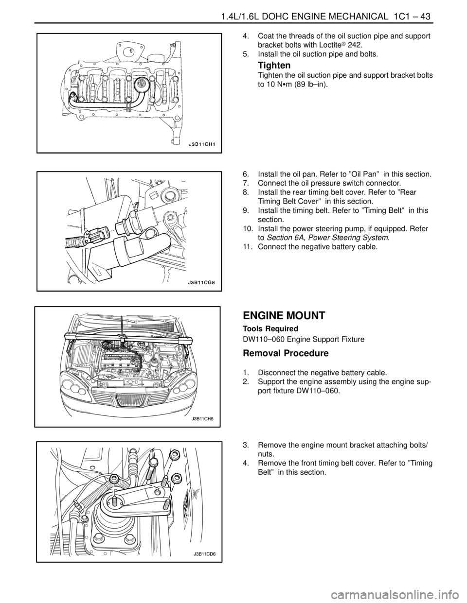
4. Coat the threads of the oil suction pipe and support
bracket bolts with Loctite® 242.
5. Install the oil suction pipe and bolts.
Tighten
Tighten the oil suction pipe and support bracket bolts
to 10 NSm (89 lb–in).
6. Install the oil pan. Refer to ”Oil Pan” in this section.
7. Connect the oil pressure switch connector.
8. Install the rear timing belt cover. Refer to ”Rear
Timing Belt Cover” in this section.
9. Install the timing belt. Refer to ”Timing Belt” in this
section.
10. Install the power steering pump, if equipped. Refer
to Section 6A, Power Steering System.
11. Connect the negative battery cable.
ENGINE MOUNT
Tools Required
DW110–060 Engine Support Fixture
Removal Procedure
1. Disconnect the negative battery cable.
2. Support the engine assembly using the engine sup-
port fixture DW110–060.
3. Remove the engine mount bracket attaching bolts/
nuts.
4. Remove the front timing belt cover. Refer to ”Timing
Belt” in this section.
Page 96 of 2643
1.4L/1.6L DOHC ENGINE MECHANICAL 1C1 – 53
DAEWOO V–121 BL4
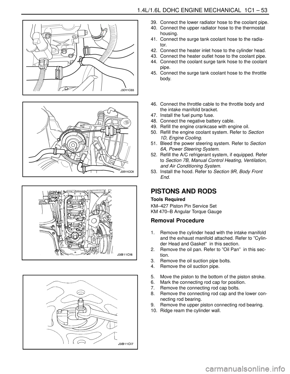
39. Connect the lower radiator hose to the coolant pipe.
40. Connect the upper radiator hose to the thermostat
housing.
41. Connect the surge tank coolant hose to the radia-
tor.
42. Connect the heater inlet hose to the cylinder head.
43. Connect the heater outlet hose to the coolant pipe.
44. Connect the coolant surge tank hose to the coolant
pipe.
45. Connect the surge tank coolant hose to the throttle
body.
46. Connect the throttle cable to the throttle body and
the intake manifold bracket.
47. Install the fuel pump fuse.
48. Connect the negative battery cable.
49. Refill the engine crankcase with engine oil.
50. Refill the engine coolant system. Refer to Section
1D, Engine Cooling.
51. Bleed the power steering system. Refer to Section
6A, Power Steering System.
52. Refill the A/C refrigerant system, if equipped. Refer
to Section 7B, Manual Control Heating, Ventilation,
and Air Conditioning System.
53. Install the hood. Refer to Section 9R, Body Front
End.
PISTONS AND RODS
Tools Required
KM–427 Piston Pin Service Set
KM 470–B Angular Torque Gauge
Removal Procedure
1. Remove the cylinder head with the intake manifold
and the exhaust manifold attached. Refer to ”Cylin-
der Head and Gasket” in this section.
2. Remove the oil pan. Refer to ”Oil Pan” in this sec-
tion.
3. Remove the oil suction pipe bolts.
4. Remove the oil suction pipe.
5. Move the piston to the bottom of the piston stroke.
6. Mark the connecting rod cap for position.
7. Remove the connecting rod cap bolts.
8. Remove the connecting rod cap and the lower con-
necting rod bearing.
9. Remove the upper piston connecting rod bearing.
10. Ridge ream the cylinder wall.
Page 170 of 2643
1C2 – 50I1.8L DOHC ENGINE MECHANICAL
DAEWOO V–121 BL4
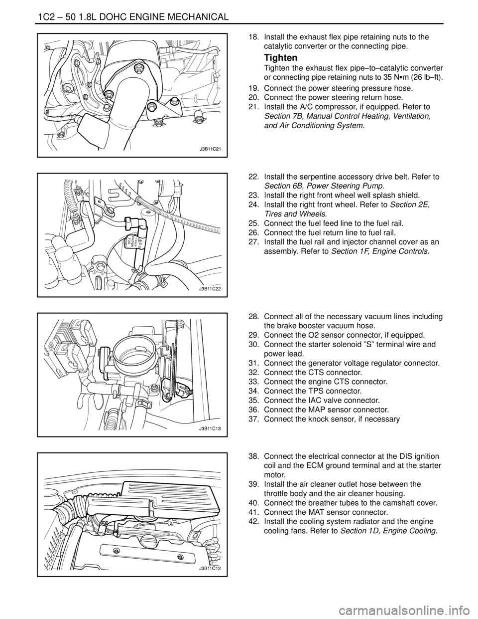
18. Install the exhaust flex pipe retaining nuts to the
catalytic converter or the connecting pipe.
Tighten
Tighten the exhaust flex pipe–to–catalytic converter
or connecting pipe retaining nuts to 35 NSm (26 lb–ft).
19. Connect the power steering pressure hose.
20. Connect the power steering return hose.
21. Install the A/C compressor, if equipped. Refer to
Section 7B, Manual Control Heating, Ventilation,
and Air Conditioning System.
22. Install the serpentine accessory drive belt. Refer to
Section 6B, Power Steering Pump.
23. Install the right front wheel well splash shield.
24. Install the right front wheel. Refer to Section 2E,
Tires and Wheels.
25. Connect the fuel feed line to the fuel rail.
26. Connect the fuel return line to fuel rail.
27. Install the fuel rail and injector channel cover as an
assembly. Refer to Section 1F, Engine Controls.
28. Connect all of the necessary vacuum lines including
the brake booster vacuum hose.
29. Connect the O2 sensor connector, if equipped.
30. Connect the starter solenoid ”S” terminal wire and
power lead.
31. Connect the generator voltage regulator connector.
32. Connect the CTS connector.
33. Connect the engine CTS connector.
34. Connect the TPS connector.
35. Connect the IAC valve connector.
36. Connect the MAP sensor connector.
37. Connect the knock sensor, if necessary
38. Connect the electrical connector at the DIS ignition
coil and the ECM ground terminal and at the starter
motor.
39. Install the air cleaner outlet hose between the
throttle body and the air cleaner housing.
40. Connect the breather tubes to the camshaft cover.
41. Connect the MAT sensor connector.
42. Install the cooling system radiator and the engine
cooling fans. Refer to Section 1D, Engine Cooling.
Page 171 of 2643
1.8L DOHC ENGINE MECHANICAL 1C2 – 51
DAEWOO V–121 BL4
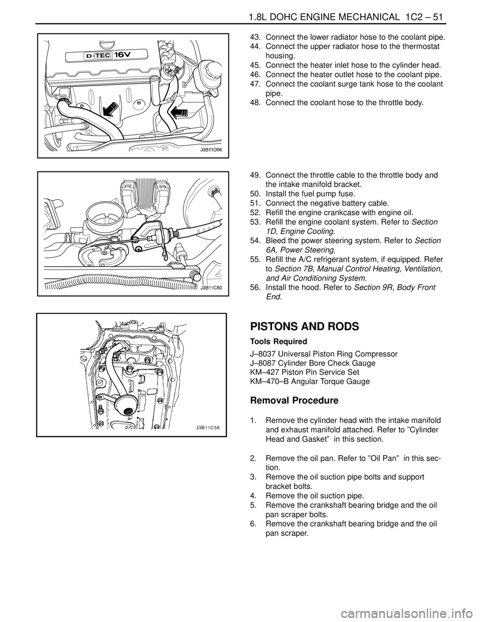
43. Connect the lower radiator hose to the coolant pipe.
44. Connect the upper radiator hose to the thermostat
housing.
45. Connect the heater inlet hose to the cylinder head.
46. Connect the heater outlet hose to the coolant pipe.
47. Connect the coolant surge tank hose to the coolant
pipe.
48. Connect the coolant hose to the throttle body.
49. Connect the throttle cable to the throttle body and
the intake manifold bracket.
50. Install the fuel pump fuse.
51. Connect the negative battery cable.
52. Refill the engine crankcase with engine oil.
53. Refill the engine coolant system. Refer to Section
1D, Engine Cooling.
54. Bleed the power steering system. Refer to Section
6A, Power Steering.
55. Refill the A/C refrigerant system, if equipped. Refer
to Section 7B, Manual Control Heating, Ventilation,
and Air Conditioning System.
56. Install the hood. Refer to Section 9R, Body Front
End.
PISTONS AND RODS
Tools Required
J–8037 Universal Piston Ring Compressor
J–8087 Cylinder Bore Check Gauge
KM–427 Piston Pin Service Set
KM–470–B Angular Torque Gauge
Removal Procedure
1. Remove the cylinder head with the intake manifold
and exhaust manifold attached. Refer to ”Cylinder
Head and Gasket” in this section.
2. Remove the oil pan. Refer to ”Oil Pan” in this sec-
tion.
3. Remove the oil suction pipe bolts and support
bracket bolts.
4. Remove the oil suction pipe.
5. Remove the crankshaft bearing bridge and the oil
pan scraper bolts.
6. Remove the crankshaft bearing bridge and the oil
pan scraper.
Page 935 of 2643

2C – 18IFRONT SUSPENSION
DAEWOO V–121 BL4
3. Connect the stabilizer shaft link to the strut assem-
bly by attaching the stabilizer link–to–strut assem-
bly nut.
Tighten
Tighten the stabilizer link–to–strut assembly nut to 47
NSm (35 lb–ft).
4. Install the brake line to the securing bracket on the
strut assembly.
5. On vehicles equipped with the ABS, connect the
ABS sensor line to the strut assembly.
6. Install the wheel. Refer to Section 2E, Tires and
Wheels.
7. Lower the vehicle.
8. Install the nuts securing the strut assembly to the
body of the vehicle.
Tighten
Tighten the strut assembly–to–body nuts to 65 NSm
(48 lb–ft).
CROSSMEMBER ASSEMBLY
Removal Procedure
1. Raise and suitably support the vehicle.
2. Remove the wheels. Refer to Section 2E, Tires and
Wheels.
3. Remove the nuts and bolts from the steering gear
mounting bracket.
4. Remove the return line bolt from the clip on the
crossmember.
5. Remove the exhaust pipe forward of the catalytic
converter. Refer to Section 1G, Engine Exhaust.
6. Disconnect the tie rod from the knuckle assembly.
Refer to Section 6C, Power Steering Gear.
7. Disconnect the ball joint from the knuckle assembly.
Refer to ”Knuckle Assembly” in this section.
8. Disconnect the stabilizer link from the strut assem-
bly. Refer to ”Stabilizer Link” in this section.
9. Remove the crossmember link–to–transaxle brack-
et nut.
1) Remove the right lower engine mount.
2) Remove the rear transmission mount bracket.
Page 937 of 2643
2C – 20IFRONT SUSPENSION
DAEWOO V–121 BL4
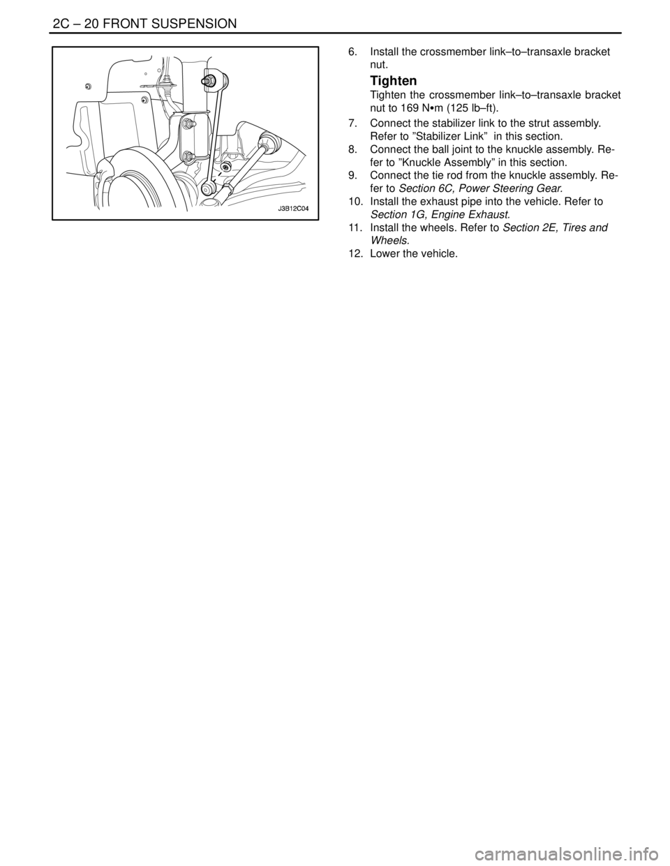
6. Install the crossmember link–to–transaxle bracket
nut.
Tighten
Tighten the crossmember link–to–transaxle bracket
nut to 169 NSm (125 lb–ft).
7. Connect the stabilizer link to the strut assembly.
Refer to ”Stabilizer Link” in this section.
8. Connect the ball joint to the knuckle assembly. Re-
fer to ”Knuckle Assembly” in this section.
9. Connect the tie rod from the knuckle assembly. Re-
fer to Section 6C, Power Steering Gear.
10. Install the exhaust pipe into the vehicle. Refer to
Section 1G, Engine Exhaust.
11. Install the wheels. Refer to Section 2E, Tires and
Wheels.
12. Lower the vehicle.
Page 1902 of 2643
SECTION : 6A
POWER STEERING SYSTEM
TABLE OF CONTENTS
SPECIFICATIONS6A–1 . . . . . . . . . . . . . . . . . . . . . . . . . .
Fastener Tightening Specifications 6A–1. . . . . . . . . . .
SPECIAL TOOLS6A–1 . . . . . . . . . . . . . . . . . . . . . . . . . . .
Special Tools Table 6A–1. . . . . . . . . . . . . . . . . . . . . . . .
DIAGNOSIS6A–2 . . . . . . . . . . . . . . . . . . . . . . . . . . . . . . . .
Power Steering System Pressure Test 6A–2. . . . . . . .
Power Steering System Leak Test 6A–2. . . . . . . . . . .
MAINTENANCE AND REPAIR6A–3 . . . . . . . . . . . . . . . ON–VEHICLE SERVICE 6A–3. . . . . . . . . . . . . . . . . . . . .
Bleeding the Power Steering System 6A–3. . . . . . . . .
Checking and Adding Fluid 6A–3. . . . . . . . . . . . . . . . . .
Fluid Reservoir 6A–4. . . . . . . . . . . . . . . . . . . . . . . . . . . .
Hoses and Pipes 6A–4. . . . . . . . . . . . . . . . . . . . . . . . . .
GENERAL DESCRIPTION AND SYSTEM
OPERATION6A–8 . . . . . . . . . . . . . . . . . . . . . . . . . . . . . .
Power Steering System 6A–8. . . . . . . . . . . . . . . . . . . . .
SPECIFICATIONS
FASTENER TIGHTENING SPECIFICATIONS
ApplicationNSmLb–FtLb–In
Power Steering Pump Pressure Line Fitting2821–
Return Line Clip Bolts8–71
Steering Gear Inlet and Outlet Pipe Fittings2821–
SPECIAL TOOLS
SPECIAL TOOLS TABLE
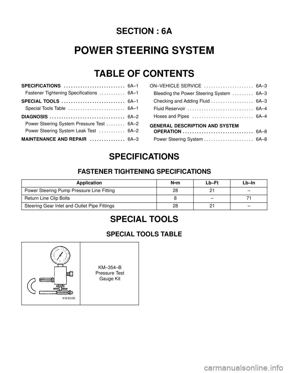
KM–354–B
Pressure Test
Gauge Kit