Page 935 of 2643

2C – 18IFRONT SUSPENSION
DAEWOO V–121 BL4
3. Connect the stabilizer shaft link to the strut assem-
bly by attaching the stabilizer link–to–strut assem-
bly nut.
Tighten
Tighten the stabilizer link–to–strut assembly nut to 47
NSm (35 lb–ft).
4. Install the brake line to the securing bracket on the
strut assembly.
5. On vehicles equipped with the ABS, connect the
ABS sensor line to the strut assembly.
6. Install the wheel. Refer to Section 2E, Tires and
Wheels.
7. Lower the vehicle.
8. Install the nuts securing the strut assembly to the
body of the vehicle.
Tighten
Tighten the strut assembly–to–body nuts to 65 NSm
(48 lb–ft).
CROSSMEMBER ASSEMBLY
Removal Procedure
1. Raise and suitably support the vehicle.
2. Remove the wheels. Refer to Section 2E, Tires and
Wheels.
3. Remove the nuts and bolts from the steering gear
mounting bracket.
4. Remove the return line bolt from the clip on the
crossmember.
5. Remove the exhaust pipe forward of the catalytic
converter. Refer to Section 1G, Engine Exhaust.
6. Disconnect the tie rod from the knuckle assembly.
Refer to Section 6C, Power Steering Gear.
7. Disconnect the ball joint from the knuckle assembly.
Refer to ”Knuckle Assembly” in this section.
8. Disconnect the stabilizer link from the strut assem-
bly. Refer to ”Stabilizer Link” in this section.
9. Remove the crossmember link–to–transaxle brack-
et nut.
1) Remove the right lower engine mount.
2) Remove the rear transmission mount bracket.
Page 936 of 2643
FRONT SUSPENSION 2C – 19
DAEWOO V–121 BL4
10. Remove the rear crossmember–to–body bolts.
CAUTION : Two technicians must hold the front
crossmember assembly and suitably support the as-
sembly with a jack stand during removal of the front
attachment bolts. Failure to support the front cross-
member properly can result in personal injury.
11. Remove the front crossmember–to–body bolts.
12. Remove the crossmember assembly from the ve-
hicle.
Installation Procedure
1. Install the crossmember assembly.
2. Install the rear crossmember–to–body bolts.
Tighten
Tighten the rear crossmember–to–body bolts to 196
NSm (145 lb–ft).
3. Install the front crossmember–to–body bolts.
Tighten
Tighten the front crossmember–to–body bolts to 130
NSm (96 lb–ft).
4. Install the bolts and nuts on the steering gear
mounting brackets.
5. Install the return line bolt into the clip on the cross-
member. Refer to Section 6C, Power Steering
Gear.
Page 937 of 2643
2C – 20IFRONT SUSPENSION
DAEWOO V–121 BL4
6. Install the crossmember link–to–transaxle bracket
nut.
Tighten
Tighten the crossmember link–to–transaxle bracket
nut to 169 NSm (125 lb–ft).
7. Connect the stabilizer link to the strut assembly.
Refer to ”Stabilizer Link” in this section.
8. Connect the ball joint to the knuckle assembly. Re-
fer to ”Knuckle Assembly” in this section.
9. Connect the tie rod from the knuckle assembly. Re-
fer to Section 6C, Power Steering Gear.
10. Install the exhaust pipe into the vehicle. Refer to
Section 1G, Engine Exhaust.
11. Install the wheels. Refer to Section 2E, Tires and
Wheels.
12. Lower the vehicle.
Page 1154 of 2643

4G – 2IPARKING BRAKE
DAEWOO V–121 BL4
MAINTENANCE AND REPAIR
ON–VEHICLE SERVICE
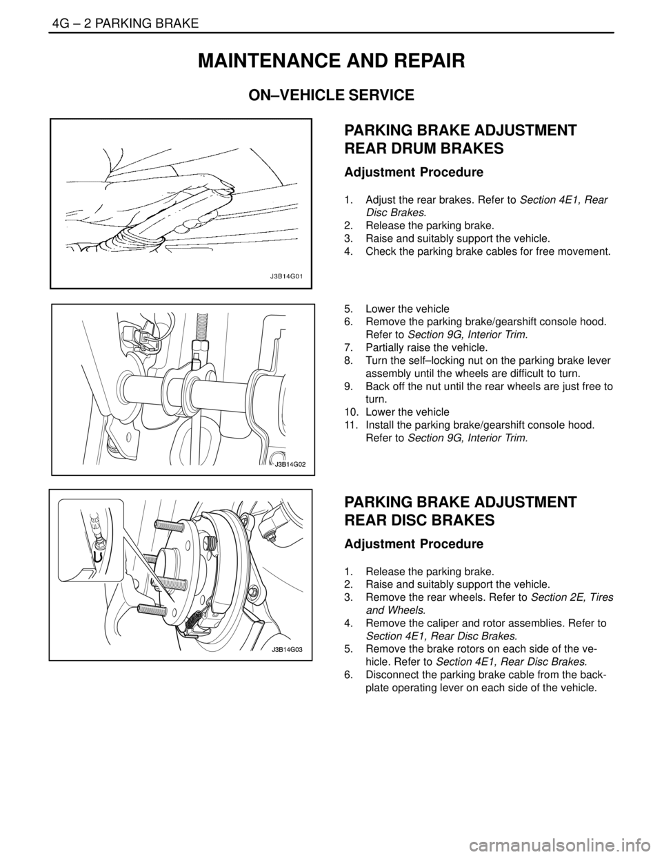
PARKING BRAKE ADJUSTMENT
REAR DRUM BRAKES
Adjustment Procedure
1. Adjust the rear brakes. Refer to Section 4E1, Rear
Disc Brakes.
2. Release the parking brake.
3. Raise and suitably support the vehicle.
4. Check the parking brake cables for free movement.
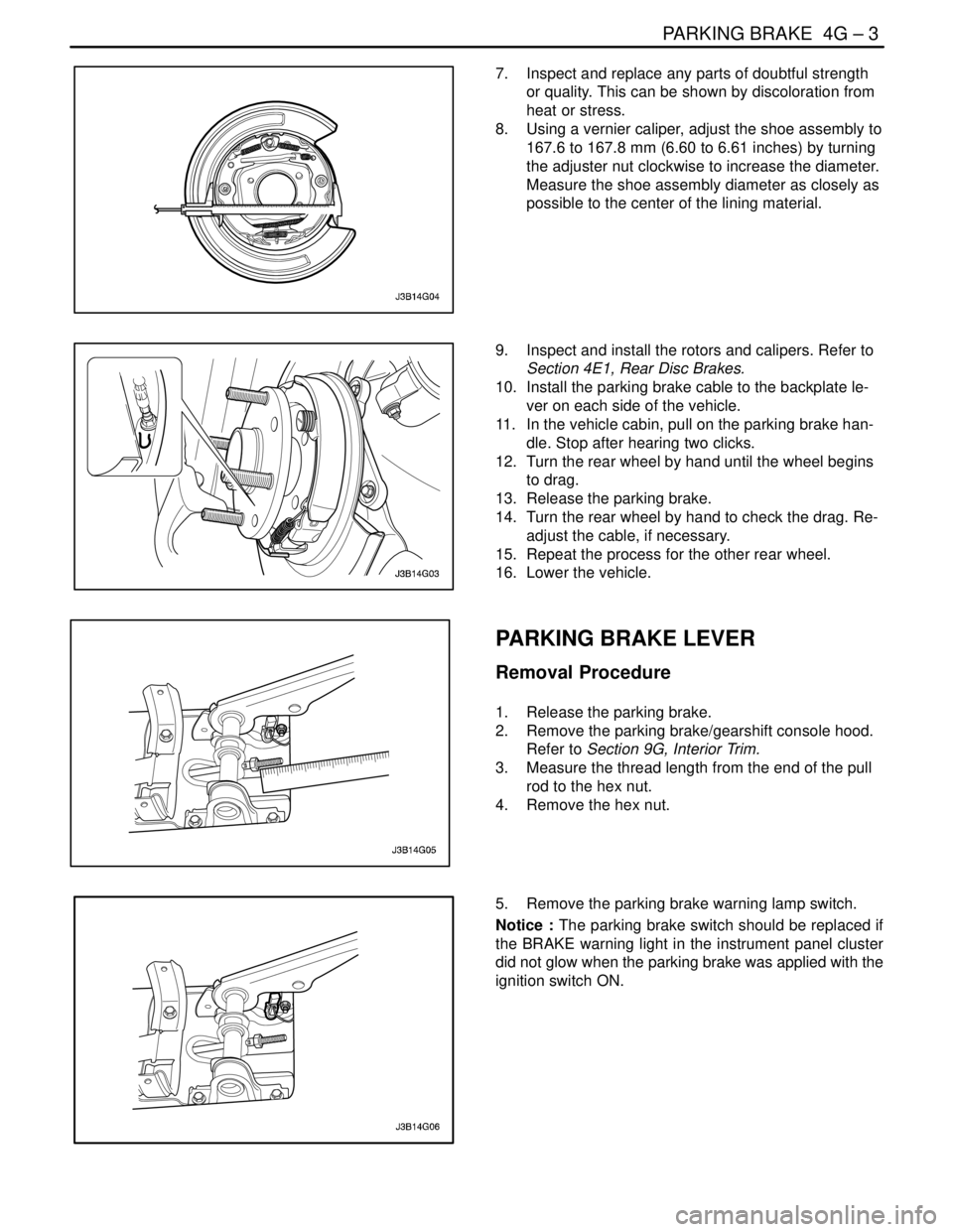
5. Lower the vehicle
6. Remove the parking brake/gearshift console hood.
Refer to Section 9G, Interior Trim.
7. Partially raise the vehicle.
8. Turn the self–locking nut on the parking brake lever
assembly until the wheels are difficult to turn.
9. Back off the nut until the rear wheels are just free to
turn.
10. Lower the vehicle
11. Install the parking brake/gearshift console hood.
Refer to Section 9G, Interior Trim.
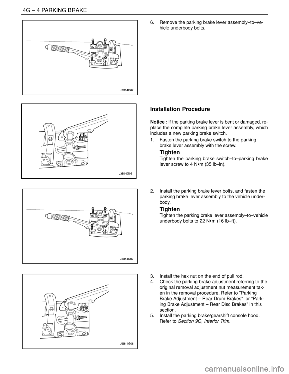
PARKING BRAKE ADJUSTMENT
REAR DISC BRAKES
Adjustment Procedure
1. Release the parking brake.
2. Raise and suitably support the vehicle.
3. Remove the rear wheels. Refer to Section 2E, Tires
and Wheels.
4. Remove the caliper and rotor assemblies. Refer to
Section 4E1, Rear Disc Brakes.
5. Remove the brake rotors on each side of the ve-
hicle. Refer to Section 4E1, Rear Disc Brakes.
6. Disconnect the parking brake cable from the back-
plate operating lever on each side of the vehicle.
Page 1155 of 2643

PARKING BRAKE 4G – 3
DAEWOO V–121 BL4
7. Inspect and replace any parts of doubtful strength
or quality. This can be shown by discoloration from
heat or stress.
8. Using a vernier caliper, adjust the shoe assembly to
167.6 to 167.8 mm (6.60 to 6.61 inches) by turning
the adjuster nut clockwise to increase the diameter.
Measure the shoe assembly diameter as closely as
possible to the center of the lining material.
9. Inspect and install the rotors and calipers. Refer to
Section 4E1, Rear Disc Brakes.
10. Install the parking brake cable to the backplate le-
ver on each side of the vehicle.
11. In the vehicle cabin, pull on the parking brake han-
dle. Stop after hearing two clicks.
12. Turn the rear wheel by hand until the wheel begins
to drag.
13. Release the parking brake.
14. Turn the rear wheel by hand to check the drag. Re-
adjust the cable, if necessary.
15. Repeat the process for the other rear wheel.
16. Lower the vehicle.
PARKING BRAKE LEVER
Removal Procedure
1. Release the parking brake.
2. Remove the parking brake/gearshift console hood.
Refer to Section 9G, Interior Trim.
3. Measure the thread length from the end of the pull
rod to the hex nut.
4. Remove the hex nut.
5. Remove the parking brake warning lamp switch.
Notice : The parking brake switch should be replaced if
the BRAKE warning light in the instrument panel cluster
did not glow when the parking brake was applied with the
ignition switch ON.
Page 1156 of 2643

4G – 4IPARKING BRAKE
DAEWOO V–121 BL4
6. Remove the parking brake lever assembly–to–ve-
hicle underbody bolts.
Installation Procedure
Notice : If the parking brake lever is bent or damaged, re-
place the complete parking brake lever assembly, which
includes a new parking brake switch.
1. Fasten the parking brake switch to the parking
brake lever assembly with the screw.
Tighten
Tighten the parking brake switch–to–parking brake
lever screw to 4 NSm (35 lb–in).
2. Install the parking brake lever bolts, and fasten the
parking brake lever assembly to the vehicle under-
body.
Tighten
Tighten the parking brake lever assembly–to–vehicle
underbody bolts to 22 NSm (16 lb–ft).
3. Install the hex nut on the end of pull rod.
4. Check the parking brake adjustment referring to the
original removal adjustment nut measurement tak-
en in the removal procedure. Refer to ”Parking
Brake Adjustment – Rear Drum Brakes” or ”Park-
ing Brake Adjustment – Rear Disc Brakes” in this
section.
5. Install the parking brake/gearshift console hood.
Refer to Section 9G, Interior Trim.
Page 1157 of 2643
PARKING BRAKE 4G – 5
DAEWOO V–121 BL4
PARKING BRAKE CABLE
Removal Procedure
1. Remove the parking brake/gearshift console hood.
Refer to Section 9G, Interior Trim.
2. Release the parking brake lever and the hex nut on
the end of pull rod.
3. Remove the parking brake cable ends from the
equalizer.
4. Raise and suitably support the vehicle.
5. Remove the rear wheels. Refer to Section 2E, Tires
and Wheels.
6. For vehicles with rear drum brakes, remove the det-
ent screw of the rear brake drum and remove the
brake drum.
7. Remove the retaining ring for the parking brake
cable.
8. Remove the plastic sleeve.
9. Remove the parking brake cable from the brake
trailing shoe lever and from the backing plate.
Page 1160 of 2643
4G – 8IPARKING BRAKE
DAEWOO V–121 BL4
9. Attach the parking brake cable ends to the equaliz-
er.
10. Adjust the hex nut on the end of pull rod. Refer to
”Parking Brake Adjustment” in this section.
11. Install the parking brake/gearshift console hood.
Refer to Section 9G, Interior Trim.
PARKING BRAKE HANDLE
Removal Procedure
1. Remove the parking brake/gearshift console hood,
detaching the parking brake lever boot. Refer to
Section 9G, Interior Trim.
2. Slip the parking brake handle off of the parking
brake lever.
Installation Procedure
1. Push the parking brake handle as far as it will go on
the parking brake lever.
2. Install the parking brake/gearshift console hood
with the parking brake lever boot. Refer to Section
9G, Interior Trim.