2004 DAEWOO LACETTI brake fluid
[x] Cancel search: brake fluidPage 1398 of 2643

ZF 4 HP 16 AUTOMATIC TRANSAXLE 5A1 – 49
DAEWOO V–121 BL4
Functional Check Procedure
Inspect
1. Install a tachometer or scan tool.
2. Operate the vehicle unit proper operating tempera-
ture is reached.
3. Drive the vehicle at 80 to 88km/h (50 to 55 mph)
with light throttle(road load).
4. Maintaining throttle position, lightly touch the brake
pedal and check for release of the TCC and a slight
increase in engine speed(rpm).
5. Release the brake slowly accelerate and check for
a reapply of the Lock up clutch and a slight de-
crease in engine speed(rpm).
Torque Converter Evaluation
Torque Converter Stator
The torque converter stator roller clutch can have one of
two different type malfunctions :
A. Stator assembly freewheels in both directions.
B. Stator assembly remains Locked up at all times.
Condition A – Poor Acceleration Low
Speed
The car tends to have poor acceleration from a stand still.
At speeds above 50 to 55km/h(30 to 35mph), the car may
act normal. If poor acceleration is noted, it should first be
determined that the exhaust system is not blocked, and
the transaxle is in 1st(First) gear when starting out.
If the engine freely accelerates to high rpm in N(Neutral),
it can be assumed that the engine and exhaust system are
normal. Checking for poor performance in ”Drive” and ”Re-
verse” will help determine if the stator is freewheeling at all
times.
Condition B – Poor Acceleration High
Speed
Engine rpm and car speed limited or restricted at high
speeds. Performance when accelerating from a standstill
is normal. Engine may overheat. Visual examination of the
converter may reveal a blue color from overheating.
If the converter has been removed, the stator roller clutch
can be checked by inserting two fingers into the splined in-
ner race of the roller clutch and trying to turn freely clock-
wise, but not turn or be very difficult to turn counter clock-
wise.
Noise
Torque converter whine is usually noticed when the ve-
hicle is stopped and the transaxle is in ”Drive” or ”Re-
verse”. The noise will increase when engine rpm is in-
creased. The noise will stop when the vehicle is moving or
when the torque converter clutch is applied because both
halves of the converter are turning at the same speed.
Perform a stall test to make sure the noise is actually com-
ing from the converter :1. Place foot on brake.
2. Put gear selector in ”Drive”.
3. Depress accelerator to approximately 1200rpm for
no more than six seconds.
Notice : If the accelerator is depressed for more than six
seconds, damage to the transaxle may occur.
A torque converter noise will increase under this load.
Important : This noise should not be confused with pump
whine noise which is usually noticeable in P (Park), N
(Neutral) and all other gear ranges. Pump whine will vary
with pressure ranges.
The torque converter should be replaced under any of the
following conditions:
S External leaks in the hub weld area.
S Converter hub is scored or damaged.
S Converter pilot is broken, damaged or fits poorly
into crankshaft.
S Steel particles are found after flushing the cooler
and cooler lines.
S Pump is damaged or steel particles are found in the
converter.
S Vehicle has TCC shudder and/or no TCC apply.
Replace only after all hydraulic and electrical diag-
noses have been made.(Lock up clutch material
may be glazed.)
S Converter has an imbalance which cannot be cor–
rected. (Refer To Converter Vibration Test Proce-
dure.)
S Converter is contaminated with engine coolant con-
taining antifreeze.
S Internal failure of stator roller clutch.
S Excess end play.
S Heavy clutch debris due to overheating (blue con-
verter).
S Steel particles or clutch lining material found in fluid
filter or on magnet when no internal parts in unit are
worn or damaged(indicates that lining material
came from converter).
The torque converter should not be replace if :
S The oil has an odor, is discolored, and there is no
evidence of metal or clutch facing particles.
S The threads in one or more of the converter bolt
holes are damaged.
–correct with thread insert.
S Transaxle failure did not display evidence of dam-
age or worn internal parts, steel particles or clutch
plate lining material in unit and inside the fluid filter.
S Vehicle has been exposed to high mileage(only).
The exception may be where the Lock up clutch
damper plate lining has seen excess wear by ve-
hicles operated in heavy and/or constant traffic,
such as taxi, delivery or police use.
Lock–Up Clutch Shudder Diagnosis
The key to diagnosing lock–up clutch(TCC) shudder is to
note when it happens and under what conditions.
Page 1410 of 2643

ZF 4 HP 16 AUTOMATIC TRANSAXLE 5A1 – 61
DAEWOO V–121 BL4
DTCDefault Action Indication Description
P0703Brake Switch Circuit
MalfunctionNo ChangeS TCM assume that the brake light always active.
S Open lock up clutch.
P0705Transmission Range Sen-
sor Circuit Malfunction
(PRNDL Input)MIL ONS The TCM will record operating conditions at the time
the diagnostic fails. This information will be stored in
the Failure Records buffer.
S Adopt Emergency/ Substitute mode and constant 4th
gear by hydraulic control.
S After ignition OFF/ON : 3rd gear by hydraulic control,
position P, R and N also possible.
P0710S Transmission Fluid
Temperature Sensor
Circuit MalfunctionNo ChangeS TCM assume the transaxle fluid temperature is
140°F (60°C).
S No influence at vehicle running.
P0715S Input Speed Sensor
Circuit MalfunctionMIL ONS The TCM will record operating conditions at the time
the diagnostic fails. This information will be stored in
the Failure Records buffer.
S Adopt Emergency/Substitute mode and constant 4th
gear by hydraulic control.
S After ignition OFF/ON : 3rd gear by hydraulic control,
position P, R and N also possible.
S Open lock up clutch.
P0716S Input Speed Sensor
Circuit Range/Perfor-
manceMIL ONS The TCM will record operating conditions at the time
the diagnostic fails. This information will be stored in
the Failure Records buffer.
S Adopt Emergency/ Substitute mode and constant 4th
gear by hydraulic control.
S After ignition OFF/ON : 3rd gear by hydraulic control,
position P, R and N also possible.
S Open lock up clutch.
P0717S Input Speed Sensor
Circuit Range/Perfor-
manceMIL ONS The TCM will record operating conditions at the time
the diagnostic fails. This information will be stored in
the Failure Records buffer.
S Adopt Emergency/ Substitute mode and constant 4th
gear by hydraulic control.
S After ignition OFF/ON : 3rd gear by hydraulic control,
position P, R and N also possible.
S Open lock up clutch.
P0720Output Speed Sensor Cir-
cuit MalfunctionMIL ONS The TCM will record operating conditions at the time
the diagnostic fails. This information will be stored in
the Failure Records buffer.
S Adopt Emergency/ Substitute mode and constant 4th
gear.
S Open lock up clutch.
P0721Output Speed Sensor Cir-
cuit Range/PerformanceMIL ONS The TCM will record operating conditions at the time
the diagnostic fails. This information will be stored in
the Failure Records buffer.
S Adopt Emergency/ Substitute mode and constant 4th
gear.
S Open lock up clutch.
Page 1539 of 2643
5A1 – 190IZF 4 HP 16 AUTOMATIC TRANSAXLE
DAEWOO V–121 BL4
MAINTENANCE AND REPAIR
ON–VEHICLE SERVICE
TRANSAXLE FLUID LEVEL
CHECKING PROCEDURE
Tools Required
DW260–070 Plug Remover/Installer
Inspection Procedure
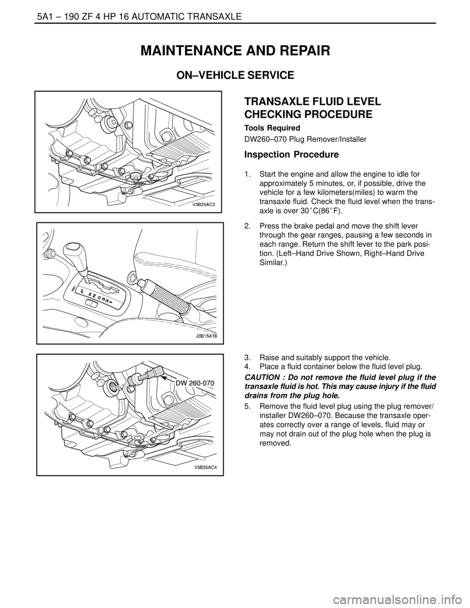
1. Start the engine and allow the engine to idle for
approximately 5 minutes, or, if possible, drive the
vehicle for a few kilometers(miles) to warm the
transaxle fluid. Check the fluid level when the trans-
axle is over 30°C(86°F).
2. Press the brake pedal and move the shift lever
through the gear ranges, pausing a few seconds in
each range. Return the shift lever to the park posi-
tion. (Left–Hand Drive Shown, Right–Hand Drive
Similar.)
3. Raise and suitably support the vehicle.
4. Place a fluid container below the fluid level plug.
CAUTION : Do not remove the fluid level plug if the
transaxle fluid is hot. This may cause injury if the fluid
drains from the plug hole.
5. Remove the fluid level plug using the plug remover/
installer DW260–070. Because the transaxle oper-
ates correctly over a range of levels, fluid may or
may not drain out of the plug hole when the plug is
removed.
Page 1581 of 2643
5A1 – 232IZF 4 HP 16 AUTOMATIC TRANSAXLE
DAEWOO V–121 BL4
GENERAL DESCRIPTION
AND SYSTEM OPERATION
The ZF 4HP 16 automatic transaxle consists primarily of
the following components.
Mechanical
S Torque converter with TCC
S Drive link assembly
S Two multiple disk clutch assemblies : Clutch B,E
S Three multiple brake assemblies : Brake C,D,F
S Lock–up clutch valve
S Two planetary gear sets
S One oil pump
S Final drive and differential assembly
Electronic
S Two shift solenoid valve(sol.1,2)
S Four pressure control solenoid valve(EDS)
S Two speed sensors : A/T ISS and A/T OSS
S Fluid temperature sensor
S Automatic transaxle control module(TCM)
S Wiring harness assembly
MECHANICAL COMPONENTS
Torque Converter
The converter consists of the impeller, the turbine wheel,
the reaction member (stator) and the oil to transmit torque.
The impeller, which is driven by the engine, causes the oil
in the converter to flow in a circular pattern. This oil flow
meets the turbine wheel, where is direction of flow is de-
flected. At the hub, the oil leaves the turbine and reaches
the reaction member (stator), where it is once again de-
flected so that it reaches the impeller at the correct angle
of flow.
The reversal effect generates movement in the stator, the
reaction torque then amplifies the turbine torque.
The ratio between turbine torque and torque is referred to
as torque multiplication.
The greater the difference is speed between the pump and
turbine, the greater the torque multiplication; it is at its
highest when the turbine is at a standstill. The higher the
speed of the turbine, the lower the torque multiplication.
When the turbine speed reaches about 85%of the pump
speed, torque multiplication=1, i.e. the turbine torque
equivalent to pump torque.
The stator, which bears against the housing via the free-
wheel, is then rotating freely in the oil flow and the free-
wheel is over–come. From this point onwards, the con-
verter acts as a straightforward fluid coupling.
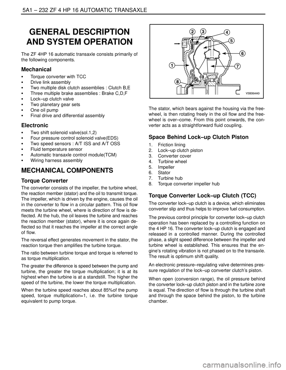
Space Behind Lock–up Clutch Piston
1. Friction lining
2. Lock–up clutch piston
3. Converter cover
4. Turbine wheel
5. Impeller
6. Stator
7. Turbine hub
8. Torque converter impeller hub
Torque Converter Lock–up Clutch (TCC)
The converter lock–up clutch is a device, which eliminates
converter slip and thus helps to improve fuel consumption.
The previous control principle for converter lock–up clutch
operation has been replaced by a controlling function on
the 4 HP 16. The converter lock–up clutch is engaged and
released in a controlled manner. During the controlled
phase, a slight speed difference between the impeller and
turbine wheel is established. This ensures that the en-
gine’s rotating vibration is not phased on to the transaxle.
The result is optimum shift quality.
An electronic pressure–regulating valve determines pres-
sure regulation of the lock–up converter clutch’s piston.
When open (conversion range), the oil pressure behind
the converter lock–up clutch piston and in the turbine zone
is equal. The direction of flow is through the turbine shaft
and through the space behind the piston, to the turbine
chamber.
Page 1582 of 2643
ZF 4 HP 16 AUTOMATIC TRANSAXLE 5A1 – 233
DAEWOO V–121 BL4
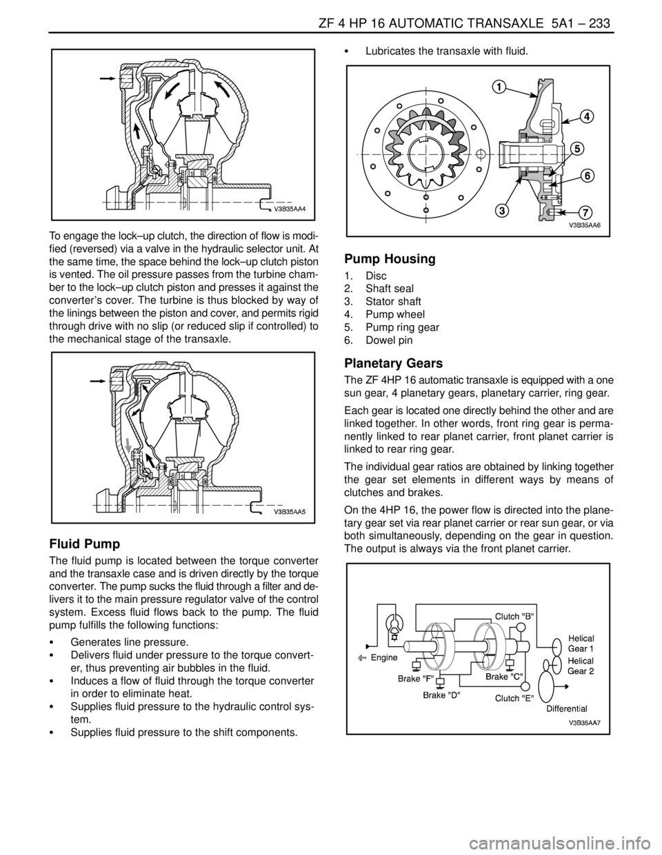
To engage the lock–up clutch, the direction of flow is modi-
fied (reversed) via a valve in the hydraulic selector unit. At
the same time, the space behind the lock–up clutch piston
is vented. The oil pressure passes from the turbine cham-
ber to the lock–up clutch piston and presses it against the
converter’s cover. The turbine is thus blocked by way of
the linings between the piston and cover, and permits rigid
through drive with no slip (or reduced slip if controlled) to
the mechanical stage of the transaxle.
Fluid Pump
The fluid pump is located between the torque converter
and the transaxle case and is driven directly by the torque
converter. The pump sucks the fluid through a filter and de-
livers it to the main pressure regulator valve of the control
system. Excess fluid flows back to the pump. The fluid
pump fulfills the following functions:
S Generates line pressure.
S Delivers fluid under pressure to the torque convert-
er, thus preventing air bubbles in the fluid.
S Induces a flow of fluid through the torque converter
in order to eliminate heat.
S Supplies fluid pressure to the hydraulic control sys-
tem.
S Supplies fluid pressure to the shift components.S Lubricates the transaxle with fluid.
Pump Housing
1. Disc
2. Shaft seal
3. Stator shaft
4. Pump wheel
5. Pump ring gear
6. Dowel pin
Planetary Gears
The ZF 4HP 16 automatic transaxle is equipped with a one
sun gear, 4 planetary gears, planetary carrier, ring gear.
Each gear is located one directly behind the other and are
linked together. In other words, front ring gear is perma-
nently linked to rear planet carrier, front planet carrier is
linked to rear ring gear.
The individual gear ratios are obtained by linking together
the gear set elements in different ways by means of
clutches and brakes.
On the 4HP 16, the power flow is directed into the plane-
tary gear set via rear planet carrier or rear sun gear, or via
both simultaneously, depending on the gear in question.
The output is always via the front planet carrier.
Page 1590 of 2643

ZF 4 HP 16 AUTOMATIC TRANSAXLE 5A1 – 241
DAEWOO V–121 BL4
TCM INPUTS THAT AFFECT THE 4HP
16 TRANSAXLE
Throttle Position Sensor
S Provides throttle position data to the TCM for deter-
mining shift patterns and TCC apply/release.
S An incorrect throttle position sensor input could
causes erratic or shift pattern, poor shift quality or
TCC function
Automatic Transaxle Output (Shaft) Speed
Sensor
S Provides vehicle speed data to the TCM for deter-
mining shift patterns and TCC apply/release, and
gear ratio calculations.
S An incorrect throttle position sensor input could
causes erratic or shift pattern, poor shift quality or
TCC function
Automatic Transaxle Input (Shaft) Speed
Sensor
S Provides transaxle input speed data to the TCM for
determining shift patterns and TCC apply/release,
and gear ratio.
Engine Coolant Temperature Sensor
S Provides coolant temperature data to the TCM for
determining initial TCC engagement.
S An incorrect engine coolant temperature sensor
input could causes an incorrect initial TCC apply
Engine Speed
S The ignition module provides engine speed data the
TCM.
S The TCM uses engine speed information for con-
trolling wide open throttle shifts and the TCC PWM
solenoid duty cycle.
Stoplamp Switch
S Provides brake apply information to the TCM for
controlling TCC apply and release.
S An incorrect TCC stoplamp switch input could
causes an incorrect TCC apply or release.
Transaxle Fluid Temperature (TFT) Sensor
S Provides transaxle fluid temperature information to
the TCM for determining alternate shift patterns and
TCC apply during high temperature conditions (hot
mode operation).
S An incorrect transaxle temperature sensor input
could causes altered shift patterns, poor shift quali-
ty and incorrect TCC apply.
Page 1895 of 2643
5C – 8ICLUTCH
DAEWOO V–121 BL4
CLUTCH RELEASE POINT
ADJUSTMENT
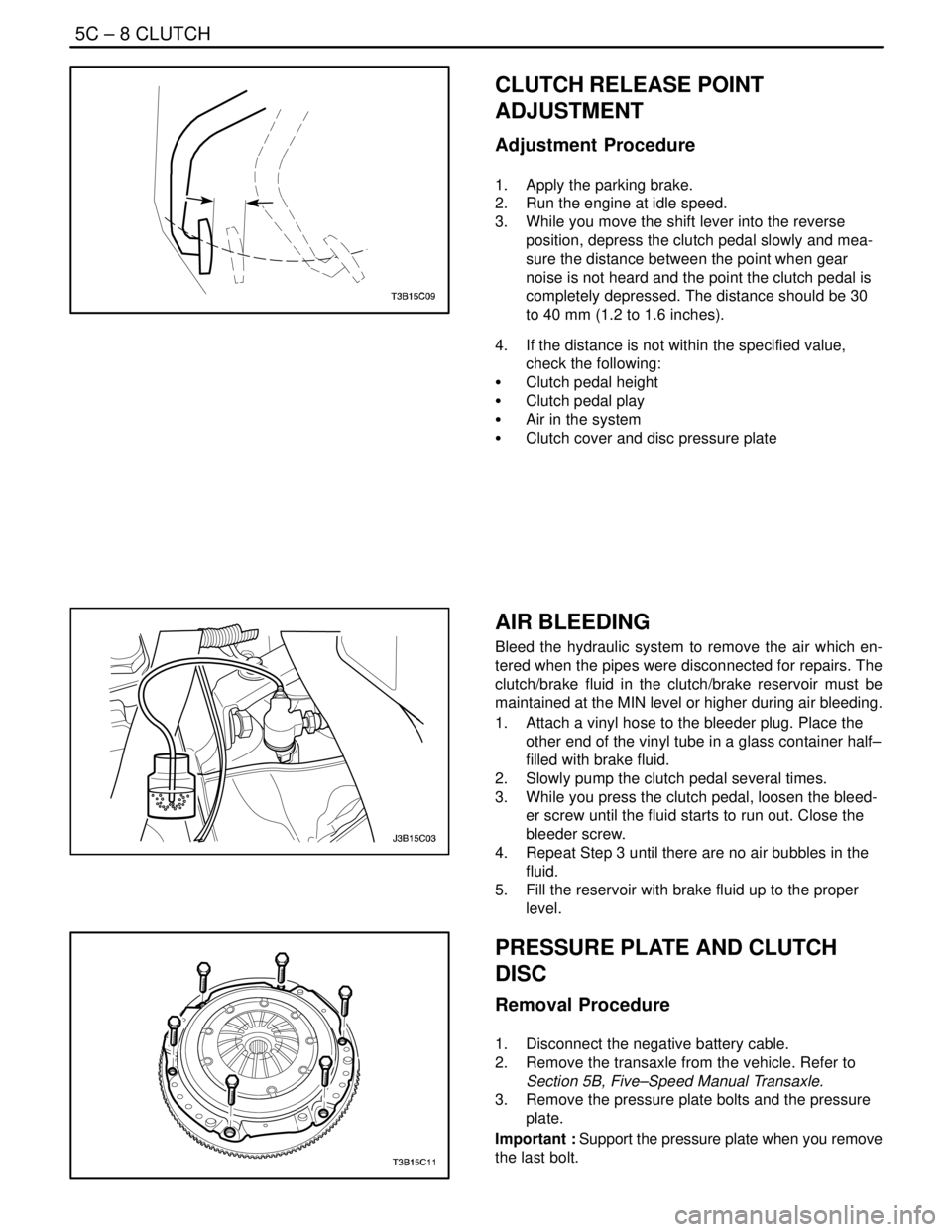
Adjustment Procedure
1. Apply the parking brake.
2. Run the engine at idle speed.
3. While you move the shift lever into the reverse
position, depress the clutch pedal slowly and mea-
sure the distance between the point when gear
noise is not heard and the point the clutch pedal is
completely depressed. The distance should be 30
to 40 mm (1.2 to 1.6 inches).
4. If the distance is not within the specified value,
check the following:
S Clutch pedal height
S Clutch pedal play
S Air in the system
S Clutch cover and disc pressure plate
AIR BLEEDING
Bleed the hydraulic system to remove the air which en-
tered when the pipes were disconnected for repairs. The
clutch/brake fluid in the clutch/brake reservoir must be
maintained at the MIN level or higher during air bleeding.
1. Attach a vinyl hose to the bleeder plug. Place the
other end of the vinyl tube in a glass container half–
filled with brake fluid.
2. Slowly pump the clutch pedal several times.
3. While you press the clutch pedal, loosen the bleed-
er screw until the fluid starts to run out. Close the
bleeder screw.
4. Repeat Step 3 until there are no air bubbles in the
fluid.
5. Fill the reservoir with brake fluid up to the proper
level.
PRESSURE PLATE AND CLUTCH
DISC
Removal Procedure
1. Disconnect the negative battery cable.
2. Remove the transaxle from the vehicle. Refer to
Section 5B, Five–Speed Manual Transaxle.
3. Remove the pressure plate bolts and the pressure
plate.
Important : Support the pressure plate when you remove
the last bolt.
Page 1897 of 2643
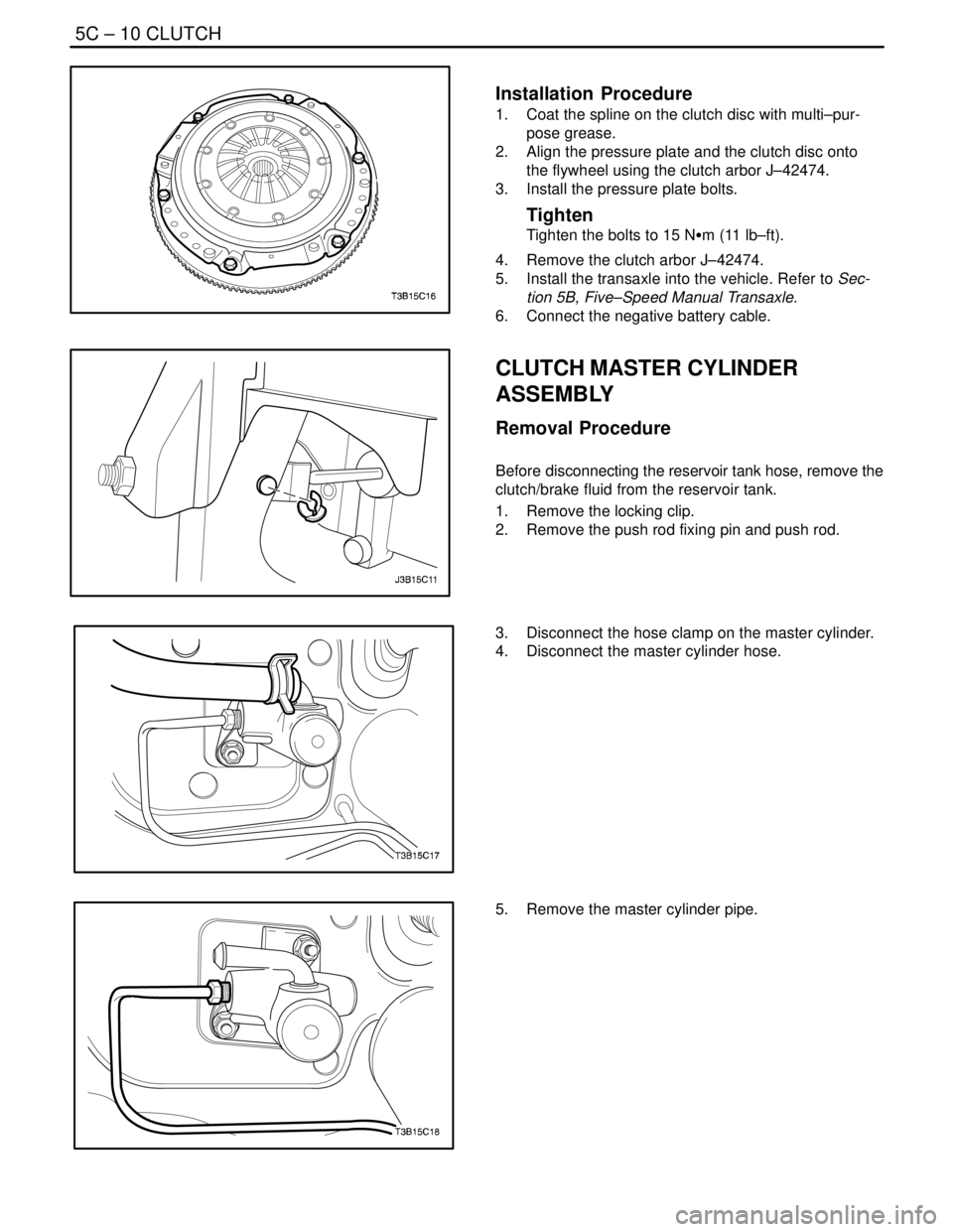
5C – 10ICLUTCH
DAEWOO V–121 BL4
Installation Procedure
1. Coat the spline on the clutch disc with multi–pur-
pose grease.
2. Align the pressure plate and the clutch disc onto
the flywheel using the clutch arbor J–42474.
3. Install the pressure plate bolts.
Tighten
Tighten the bolts to 15 NSm (11 lb–ft).
4. Remove the clutch arbor J–42474.
5. Install the transaxle into the vehicle. Refer to Sec-
tion 5B, Five–Speed Manual Transaxle.
6. Connect the negative battery cable.
CLUTCH MASTER CYLINDER
ASSEMBLY
Removal Procedure
Before disconnecting the reservoir tank hose, remove the
clutch/brake fluid from the reservoir tank.
1. Remove the locking clip.
2. Remove the push rod fixing pin and push rod.
3. Disconnect the hose clamp on the master cylinder.
4. Disconnect the master cylinder hose.
5. Remove the master cylinder pipe.