Page 1062 of 2643
REAR DISC BRAKES 4E1 – 5
DAEWOO V–121 BL4
2. Connect the brake hose with the bolt and ring
seals.
Tighten
Tighten the brake hose inlet bolt and ring seals to 32
NSm (24 lb–ft).
3. Install the rear wheels. Refer to Section 2E, Tires
and Wheels.
4. Lower the vehicle.
5. Fill the master cylinder to the proper level with
clean brake fluid.
6. Bleed the caliper. Refer to Section 4F, Antilock
Brake System and Traction Control System.
ROTOR
Removal Procedure
1. Remove the caliper. Refer to ”Caliper” in this sec-
tion.
2. Remove the brake shoes.
3. Remove the caliper mounting bracket.
4. Remove the rotor detent screw.
5. Remove the rotor.
Installation Procedure
Important : To guarantee uniform braking, always refinish
both rotors even if only one rotor is defective.
1. Install the rotor on the front wheel hub and install
the detent screw.
Tighten
Tighten the rotor detent screw to 4 NSm (35 lb–in)
Page 1067 of 2643

4E1 – 10IREAR DISC BRAKES
DAEWOO V–121 BL4
UNIT REPAIR
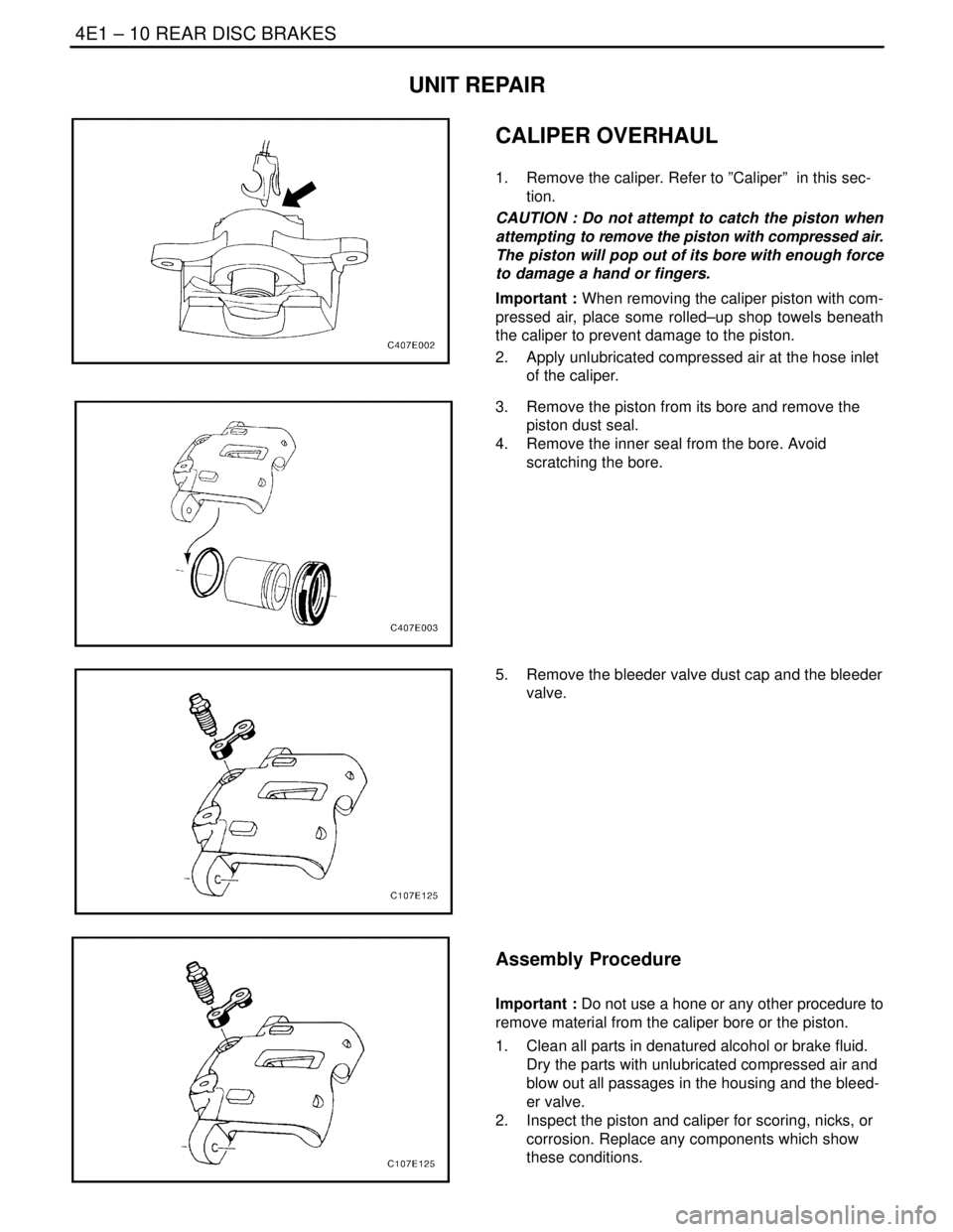
CALIPER OVERHAUL
1. Remove the caliper. Refer to ”Caliper” in this sec-
tion.
CAUTION : Do not attempt to catch the piston when
attempting to remove the piston with compressed air.
The piston will pop out of its bore with enough force
to damage a hand or fingers.
Important : When removing the caliper piston with com-
pressed air, place some rolled–up shop towels beneath
the caliper to prevent damage to the piston.
2. Apply unlubricated compressed air at the hose inlet
of the caliper.
3. Remove the piston from its bore and remove the
piston dust seal.
4. Remove the inner seal from the bore. Avoid
scratching the bore.
5. Remove the bleeder valve dust cap and the bleeder
valve.
Assembly Procedure
Important : Do not use a hone or any other procedure to
remove material from the caliper bore or the piston.
1. Clean all parts in denatured alcohol or brake fluid.
Dry the parts with unlubricated compressed air and
blow out all passages in the housing and the bleed-
er valve.
2. Inspect the piston and caliper for scoring, nicks, or
corrosion. Replace any components which show
these conditions.
Page 1068 of 2643
REAR DISC BRAKES 4E1 – 11
DAEWOO V–121 BL4
3. Install the bleeder valve and the dust cap.
3. Lubricate a new piston inner seal with brake fluid.
4. Install the piston inner seal into the groove in the
caliper bore.
5. Install the piston dust seal in its groove.
6. Lubricate the piston with brake fluid.
7. Push the piston inward until it is properly seated.
Make sure that the dust seal is in the correct
groove in the piston and the caliper.
8. Reinstall the caliper. Refer to ”Caliper” in this sec-
tion.
9. Bleed the brake system. Refer to Section 4F, Anti–
lock Brake System.
Page 1069 of 2643

4E1 – 12IREAR DISC BRAKES
DAEWOO V–121 BL4
GENERAL DESCRIPTION
AND SYSTEM OPERATION
DISC BRAKE CALIPER ASSEMBLY
The caliper has a single bore and is mounted to the steer-
ing knuckle with two mounting bolts. Hydraulic pressure,
created by applying the brake pedal, is converted by the
caliper to a stopping force. This force acts equally against
the piston and the bottom of the caliper bore to move the
piston outward and to slide the caliper inward, resulting in
a clamping action on the rotor. This clamping action forces
the linings against the rotor, creating friction to stop the ve-
hicle.S Replace all components included in the repair kits
used to service the caliper.
S Lubricate the rubber parts with clean brake fluid to
ease assembly.
S Do not use lubricated shop air on brake parts, as
damage to the rubber components may result.
S If any hydraulic component is removed or discon-
nected, it may be necessary to bleed all or part of
the brake system. Refer to Section 4F, Anti–lock
Brake System.
S Replace the shoes in axle sets only.
S The torque values specified are for dry, unlubri-
cated fasteners.
S Perform the service operations on a clean bench,
free from oily material.
Page 1076 of 2643

REAR DRUM BRAKES 4E2 – 7
DAEWOO V–121 BL4
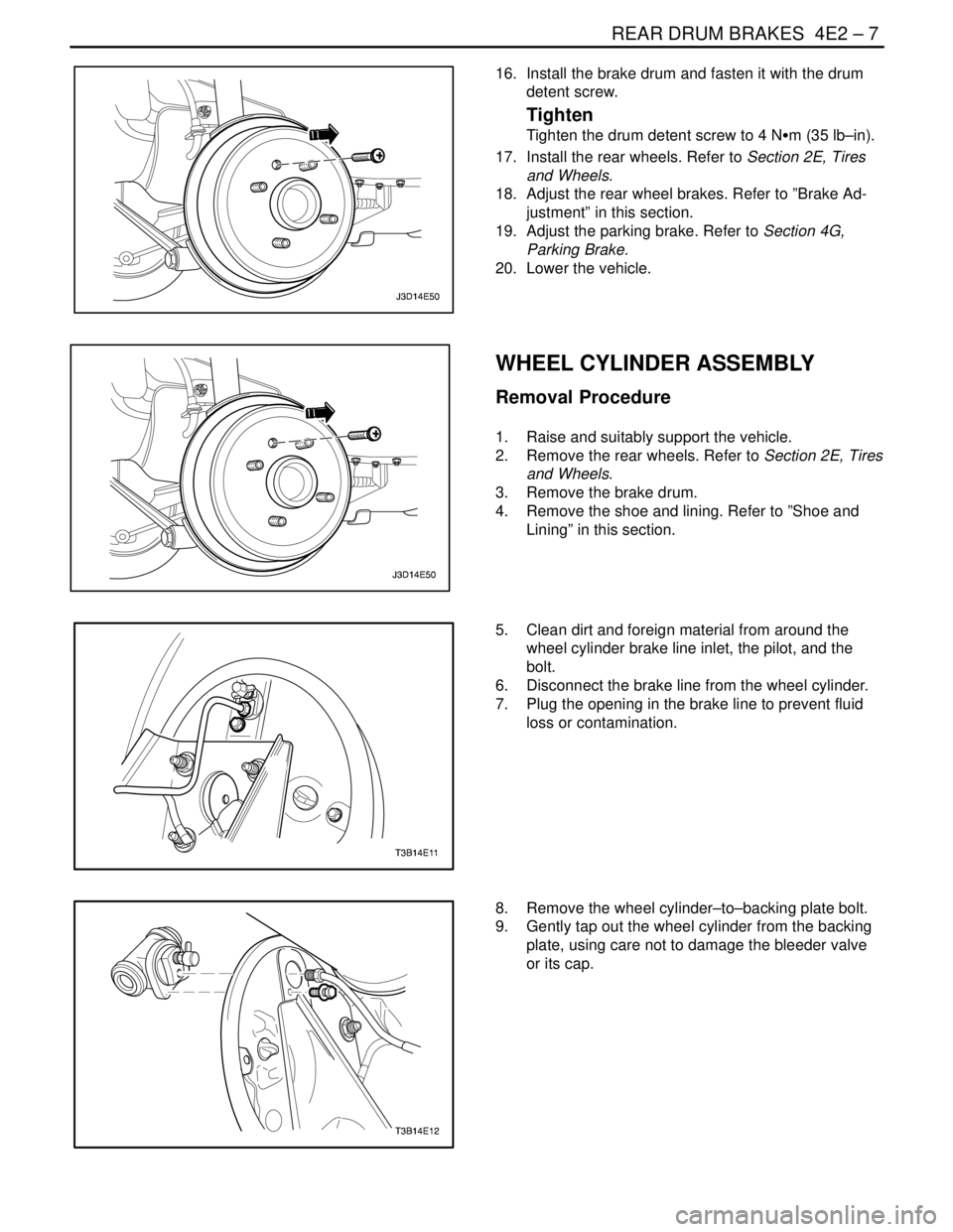
16. Install the brake drum and fasten it with the drum
detent screw.
Tighten
Tighten the drum detent screw to 4 NSm (35 lb–in).
17. Install the rear wheels. Refer to Section 2E, Tires
and Wheels.
18. Adjust the rear wheel brakes. Refer to ”Brake Ad-
justment” in this section.
19. Adjust the parking brake. Refer to Section 4G,
Parking Brake.
20. Lower the vehicle.
WHEEL CYLINDER ASSEMBLY
Removal Procedure
1. Raise and suitably support the vehicle.
2. Remove the rear wheels. Refer to Section 2E, Tires
and Wheels.
3. Remove the brake drum.
4. Remove the shoe and lining. Refer to ”Shoe and
Lining” in this section.
5. Clean dirt and foreign material from around the
wheel cylinder brake line inlet, the pilot, and the
bolt.
6. Disconnect the brake line from the wheel cylinder.
7. Plug the opening in the brake line to prevent fluid
loss or contamination.
8. Remove the wheel cylinder–to–backing plate bolt.
9. Gently tap out the wheel cylinder from the backing
plate, using care not to damage the bleeder valve
or its cap.
Page 1077 of 2643

4E2 – 8IREAR DRUM BRAKES
DAEWOO V–121 BL4
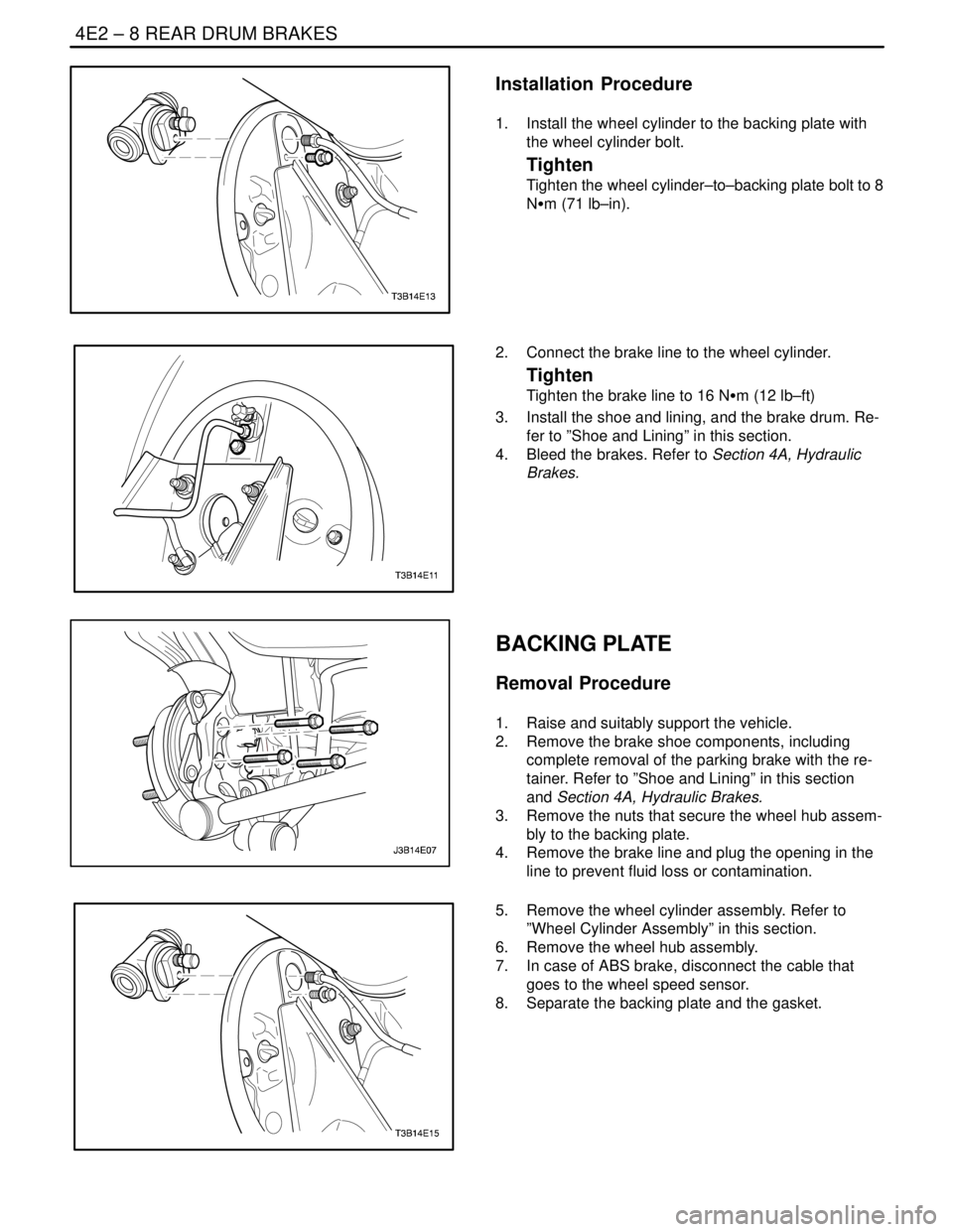
Installation Procedure
1. Install the wheel cylinder to the backing plate with
the wheel cylinder bolt.
Tighten
Tighten the wheel cylinder–to–backing plate bolt to 8
NSm (71 lb–in).
2. Connect the brake line to the wheel cylinder.
Tighten
Tighten the brake line to 16 NSm (12 lb–ft)
3. Install the shoe and lining, and the brake drum. Re-
fer to ”Shoe and Lining” in this section.
4. Bleed the brakes. Refer to Section 4A, Hydraulic
Brakes.
BACKING PLATE
Removal Procedure
1. Raise and suitably support the vehicle.
2. Remove the brake shoe components, including
complete removal of the parking brake with the re-
tainer. Refer to ”Shoe and Lining” in this section
and Section 4A, Hydraulic Brakes.
3. Remove the nuts that secure the wheel hub assem-
bly to the backing plate.
4. Remove the brake line and plug the opening in the
line to prevent fluid loss or contamination.
5. Remove the wheel cylinder assembly. Refer to
”Wheel Cylinder Assembly” in this section.
6. Remove the wheel hub assembly.
7. In case of ABS brake, disconnect the cable that
goes to the wheel speed sensor.
8. Separate the backing plate and the gasket.
Page 1079 of 2643

4E2 – 10IREAR DRUM BRAKES
DAEWOO V–121 BL4
UNIT REPAIR
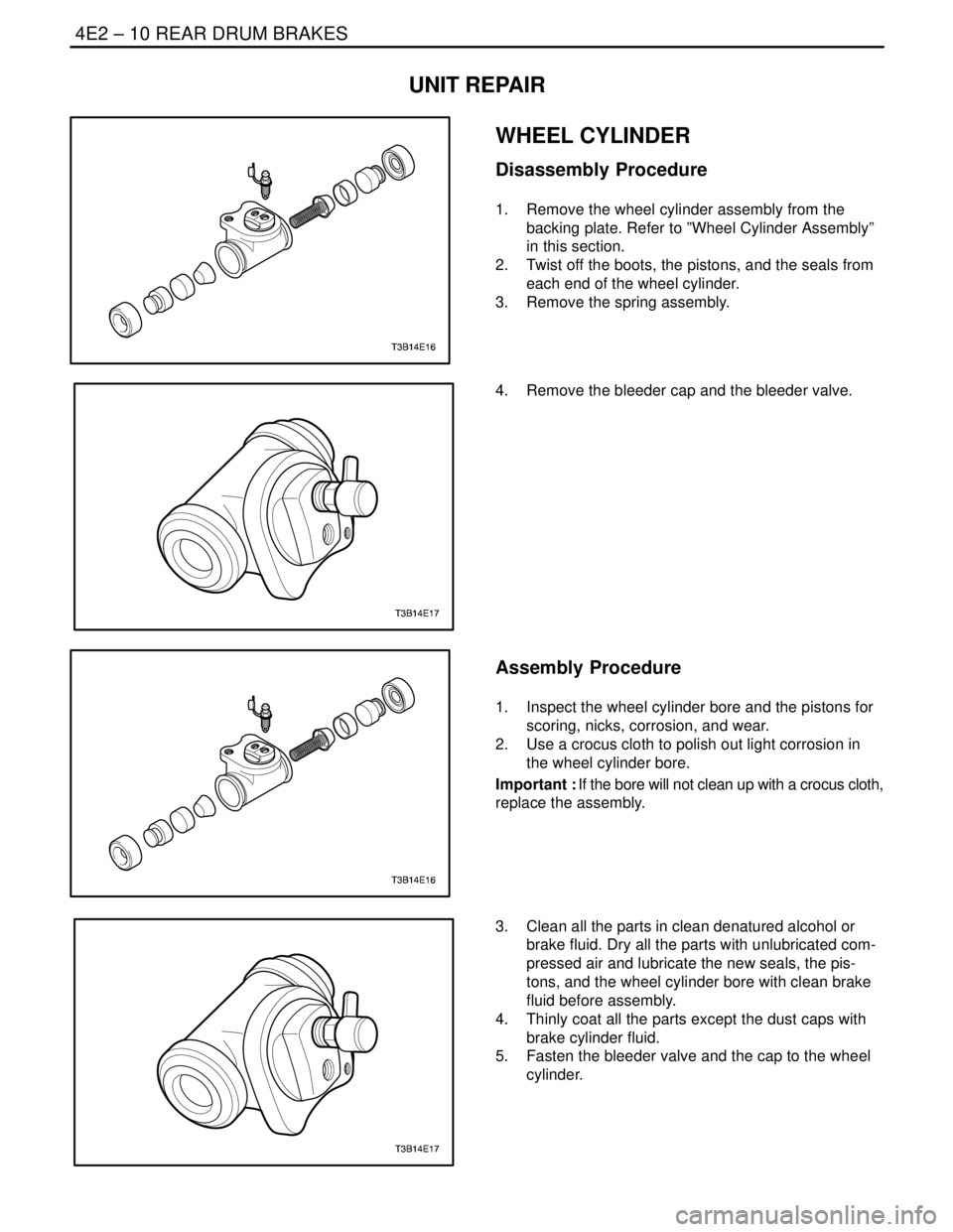
WHEEL CYLINDER
Disassembly Procedure
1. Remove the wheel cylinder assembly from the
backing plate. Refer to ”Wheel Cylinder Assembly”
in this section.
2. Twist off the boots, the pistons, and the seals from
each end of the wheel cylinder.
3. Remove the spring assembly.
4. Remove the bleeder cap and the bleeder valve.
Assembly Procedure
1. Inspect the wheel cylinder bore and the pistons for
scoring, nicks, corrosion, and wear.
2. Use a crocus cloth to polish out light corrosion in
the wheel cylinder bore.
Important : If the bore will not clean up with a crocus cloth,
replace the assembly.
3. Clean all the parts in clean denatured alcohol or
brake fluid. Dry all the parts with unlubricated com-
pressed air and lubricate the new seals, the pis-
tons, and the wheel cylinder bore with clean brake
fluid before assembly.
4. Thinly coat all the parts except the dust caps with
brake cylinder fluid.
5. Fasten the bleeder valve and the cap to the wheel
cylinder.
Page 1085 of 2643
4F – 4IANTILOCK BRAKE SYSTEM
DAEWOO V–121 BL4
ABS SYSTEM CIRCUIT (II)
60A
REDEf2
2
C107
J3B14F02
Oil feeding
Connector
BLK/WHT
G106
10A30
F4
32 43
A19
A13 A14
S301A1 C201 C201
31C201 C201 C201
C202
C110
C110
C101
C106C202 WHT
BRN BRN BRN
DLC
(Data Link
Connector) LT GRN
DK
GRN
DK
GRN LT GRN/
BLK
LT GRN/
BLK
LT GRN
LT GRN LT GRN
LT GRN LT GRN
DK BLU
DK BLUDK BLUDK BLU
DK BLU
DK BLU
ECM
”53” Ter.
(Sirius D4)ECM
”K7” Ter.
(MR–140)PPL/
WHT
PPL/
WHT
WHT/
YELPPL/WHTPPL/WHT
PPL/WHT PPL/WHT ABS
Warning
LampTCS
Warning
LampParking
Brake
Warning
Lamp
Hot in Run and Start
Hot at all times
PNK
Cluster I/P
Fuse
Block
PNK
EBCMBrake Fluid
Switch
”1” Ter.
Parking Brake
Switch 8
88 9
92 20 2222 16
41
3
42
1
11
12
19
12 432
1
21
25 23 11
6C110
C202
10A30
F11
62B15
15 15