Page 1767 of 2643
AISIN AUTOMATIC TRANSAXLE 5A2 – 177
DAEWOO V–121 BL4
11. Install the direct clutch on the oil pump.
WARNING : USE CAUTION WHEN CHECKING COM-
PONENTS WITH COMPRESSED AIR OR PERSONAL
INJURY MAY RESULT.
12. Using a dial indicator, measure the direct clutch
piston stroke while applying and releasing 392 kPa
(57 psi) .of compressed air .
Piston stroke: 0.4 � 0.8 mm (0.016 � 0.031 in.)
S If the piston stroke is less than the limit of piston
stroke, parts may have been assembled incor-
rectly, so check and reassemble again.
S If the stroke is non–standard, select another
flange.
S There are 3 flanges in different thickness.
S Flange Thickness: mm (in.)
No
ThicknessNoThickness
13.0 (0.118)33.4 (0.134)
23.2 (0.126)
Page 1774 of 2643

5A2 – 184IAISIN AUTOMATIC TRANSAXLE
DAEWOO V–121 BL4
Tools Required
DW240–020 Brake/Clutch Spring Compressor
DW240–030 Forward Clutch Adapter
DW240–120 Measuring Terminal
Disassembly Procedure
WARNING : USE CAUTION WHEN CHECKING COM-
PONENTS WITH COMPRESSED AIR OR PERSONAL
INJURY MAY RESULT.
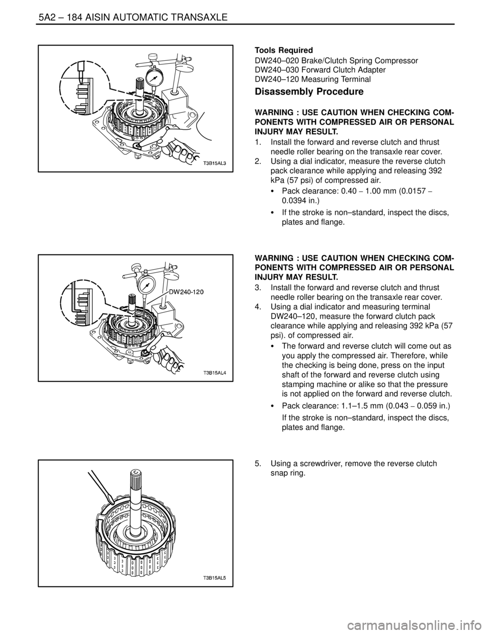
1. Install the forward and reverse clutch and thrust
needle roller bearing on the transaxle rear cover.
2. Using a dial indicator, measure the reverse clutch
pack clearance while applying and releasing 392
kPa (57 psi) of compressed air.
S Pack clearance: 0.40 � 1.00 mm (0.0157 �
0.0394 in.)
S If the stroke is non–standard, inspect the discs,
plates and flange.
WARNING : USE CAUTION WHEN CHECKING COM-
PONENTS WITH COMPRESSED AIR OR PERSONAL
INJURY MAY RESULT.
3. Install the forward and reverse clutch and thrust
needle roller bearing on the transaxle rear cover.
4. Using a dial indicator and measuring terminal
DW240–120, measure the forward clutch pack
clearance while applying and releasing 392 kPa (57
psi). of compressed air.
S The forward and reverse clutch will come out as
you apply the compressed air. Therefore, while
the checking is being done, press on the input
shaft of the forward and reverse clutch using
stamping machine or alike so that the pressure
is not applied on the forward and reverse clutch.
S Pack clearance: 1.1–1.5 mm (0.043 � 0.059 in.)
If the stroke is non–standard, inspect the discs,
plates and flange.
5. Using a screwdriver, remove the reverse clutch
snap ring.
Page 1776 of 2643

5A2 – 186IAISIN AUTOMATIC TRANSAXLE
DAEWOO V–121 BL4
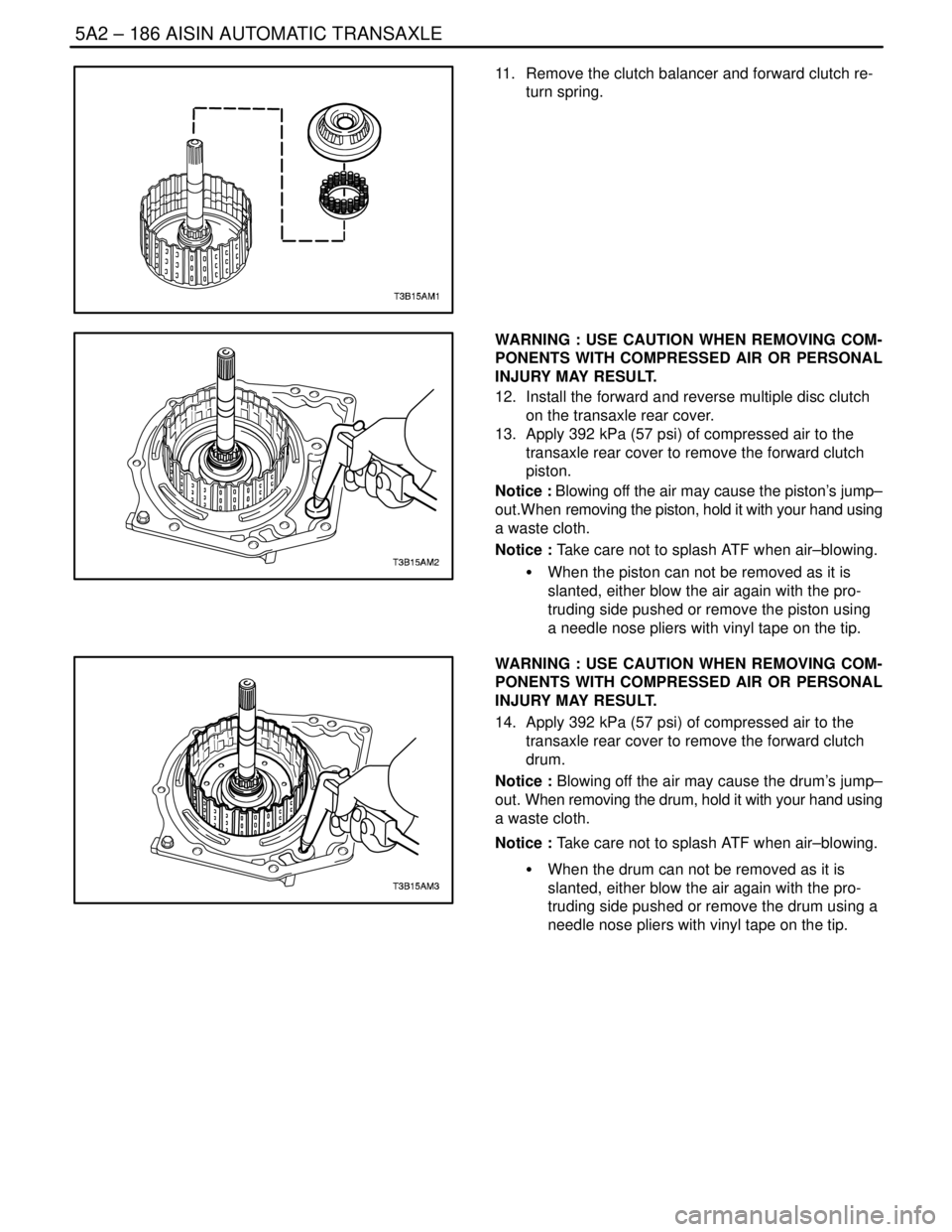
11. Remove the clutch balancer and forward clutch re-
turn spring.
WARNING : USE CAUTION WHEN REMOVING COM-
PONENTS WITH COMPRESSED AIR OR PERSONAL
INJURY MAY RESULT.
12. Install the forward and reverse multiple disc clutch
on the transaxle rear cover.
13. Apply 392 kPa (57 psi) of compressed air to the
transaxle rear cover to remove the forward clutch
piston.
Notice : Blowing off the air may cause the piston’s jump–
out.When removing the piston, hold it with your hand using
a waste cloth.
Notice : Take care not to splash ATF when air–blowing.
S When the piston can not be removed as it is
slanted, either blow the air again with the pro-
truding side pushed or remove the piston using
a needle nose pliers with vinyl tape on the tip.
WARNING : USE CAUTION WHEN REMOVING COM-
PONENTS WITH COMPRESSED AIR OR PERSONAL
INJURY MAY RESULT.
14. Apply 392 kPa (57 psi) of compressed air to the
transaxle rear cover to remove the forward clutch
drum.
Notice : Blowing off the air may cause the drum’s jump–
out. When removing the drum, hold it with your hand using
a waste cloth.
Notice : Take care not to splash ATF when air–blowing.
S When the drum can not be removed as it is
slanted, either blow the air again with the pro-
truding side pushed or remove the drum using a
needle nose pliers with vinyl tape on the tip.
Page 1780 of 2643

5A2 – 190IAISIN AUTOMATIC TRANSAXLE
DAEWOO V–121 BL4
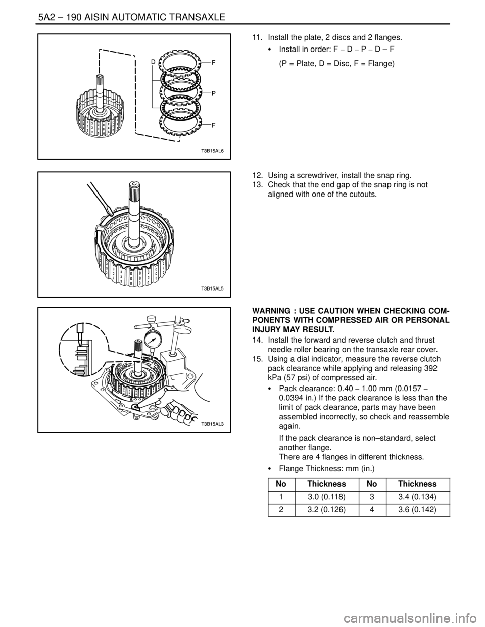
11. Install the plate, 2 discs and 2 flanges.
S Install in order: F � D � P � D – F
(P = Plate, D = Disc, F = Flange)
12. Using a screwdriver, install the snap ring.
13. Check that the end gap of the snap ring is not
aligned with one of the cutouts.
WARNING : USE CAUTION WHEN CHECKING COM-
PONENTS WITH COMPRESSED AIR OR PERSONAL
INJURY MAY RESULT.
14. Install the forward and reverse clutch and thrust
needle roller bearing on the transaxle rear cover.
15. Using a dial indicator, measure the reverse clutch
pack clearance while applying and releasing 392
kPa (57 psi) of compressed air.
S Pack clearance: 0.40 � 1.00 mm (0.0157 �
0.0394 in.) If the pack clearance is less than the
limit of pack clearance, parts may have been
assembled incorrectly, so check and reassemble
again.
If the pack clearance is non–standard, select
another flange.
There are 4 flanges in different thickness.
S Flange Thickness: mm (in.)
No
ThicknessNoThickness
13.0 (0.118)33.4 (0.134)
23.2 (0.126)43.6 (0.142)
Page 1926 of 2643

POWER STEERING GEAR 6C – 9
DAEWOO V–121 BL4
StepNo Yes Value(s) Action
23Repair the open, short to ground, short to B+, or poor
terminal contact between terminal 14 of the SSPS
control module connector and terminal 2 of the
steering wheel rotation sensor connector.
Is the repair complete?–System OK–
241. Turn the ignition OFF.
2. Connect the SSPS control module.
3. Connect the steering wheel rotation sensor.
4. Turn the ignition ON.
5. Backprobe with a voltmeter from terminal 5 on
the control module connector to the ground.
6. Rotate the steering wheel quickly in both direc-
tions.
Does the voltage show an increase and decrease
from the specified value?� 3 VGo to Step 25Go to Step 26
25Replace the SSPS control module.
Is the repair complete?–System OK–
26Replace the steering wheel rotation sensor.
Is the repair complete?–System OK–
SPEED SENSITIVE POWER STEERING SYSTEM
OPERATING WITH DECREASED ASSIST AT ALL TIMES
StepActionValue(s)YesNo
1Check the speedometer.
Is speedometer inoperative?–Go to
Section5,
TransaxleGo to Step 2
2Disconnect the EVO solenoid actuator at the power
steering pump.
Is the symptom still present?–Go to
Section 6A,
Power Steering
SystemGo to Step 3
3Replace the speed sensitive poser steering (SSPS)
control module.
Is repair complete?–System OK–
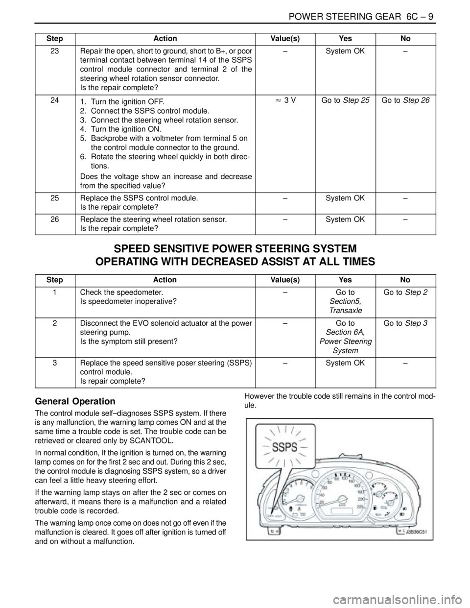
General Operation
The control module self–diagnoses SSPS system. If there
is any malfunction, the warning lamp comes ON and at the
same time a trouble code is set. The trouble code can be
retrieved or cleared only by SCANTOOL.
In normal condition, If the ignition is turned on, the warning
lamp comes on for the first 2 sec and out. During this 2 sec,
the control module is diagnosing SSPS system, so a driver
can feel a little heavy steering effort.
If the warning lamp stays on after the 2 sec or comes on
afterward, it means there is a malfunction and a related
trouble code is recorded.
The warning lamp once come on does not go off even if the
malfunction is cleared. It goes off after ignition is turned off
and on without a malfunction.However the trouble code still remains in the control mod-
ule.
Page 1927 of 2643
6C – 10IPOWER STEERING GEAR
DAEWOO V–121 BL4
Trouble Code
DTCTroubleDefault Action
01Actuator circuit open
02Actuator HI to LO short
03Actuator circuit short to B+
04Actuator HI short to GroundWarning lamp ON, Actuator Off
05Actuator LO short to Ground
06Steering Wheel Speed Sensor Open
07Steering Wheel Speed Sensor short to 5V
08Battey Voltage Out of Range (9~16 V)
Page 1954 of 2643
POWER STEERING GEAR 6C – 37
DAEWOO V–121 BL4
[Vehicle Speed – Actuator Current Relation]
SOLENOID RESISTANCE
13 W
The control module is installed on the right side of the au-
dio and can be accessible after the glove box is removed.
It receives signals from the vehicle speed sensor and the
steering wheel rotation sensor and processes them to de-
cide proper fluid flow through the actuator.
It also has a self–diagnosis. If it detects any malfunction,
it starts default mode, which is basically actuator full open
for light steering effort.
TERMINALCOLORFUNCTION
1SBActuator Low
2VActuator High
3BWSteering Wheel Sensor Ground
4–Not used
5GrSteering Wheel Sensor 5V ref.
6GWVSS
7–Not Used
8PIGN ON
9BrWarning Lamp
10BWGround
11–Not Used
12–Not Used
13LDiagnosis
14SBSteering Wheel Sensor Signal
Page 2096 of 2643

SECTION : 8A
SEAT BELTS
CAUTION : Disconnect the negative battery cable before removing or installing any electrical unit or when a tool
or equipment could easily come in contact with exposed electrical terminals. Disconnecting this cable will help
prevent personal injury and damage to the vehicle. The ignition must also be in LOCK unless otherwise noted.
TABLE OF CONTENTS
SPECIFICATIONS8A–1 . . . . . . . . . . . . . . . . . . . . . . . . . .
Fastener Tightening Specifications 8A–1. . . . . . . . . . .
SCHEMATIC AND ROUTING DIAGRAMS8A–2 . . . . .
Driver Seat Belt Warning 8A–2. . . . . . . . . . . . . . . . . . . .
DIAGNOSIS8A–3 . . . . . . . . . . . . . . . . . . . . . . . . . . . . . . . .
Driver Seat Belt Warning 8A–3. . . . . . . . . . . . . . . . . . . .
MAINTENANCE AND REPAIR8A–4 . . . . . . . . . . . . . . .
ON–VEHICLE SERVICE 8A–4. . . . . . . . . . . . . . . . . . . . .
Pretensioner Front Seat Belt 8A–4. . . . . . . . . . . . . . . .
Front Seat Belt Height Adjuster 8A–5. . . . . . . . . . . . . . Three–Point Rear Seat Belt (LH,CENTER, RH) 8A–6
Front Seat Belt Buckle 8A–7. . . . . . . . . . . . . . . . . . . . .
GENERAL DESCRIPTION AND SYSTEM
OPERATION 8A–9 . . . . . . . . . . . . . . . . . . . . . . . . . . . . .
Driver Seat Belt Warning 8A–9. . . . . . . . . . . . . . . . . . . .
Three–Point ELR Front Seat Belt With
Pretensioner 8A–9. . . . . . . . . . . . . . . . . . . . . . . . . . . .
Three–Point CLR (ELR) Rear Outboard Seat
Belt 8A–9. . . . . . . . . . . . . . . . . . . . . . . . . . . . . . . . . . . .
Operational and Functional Checks 8A–9. . . . . . . . . .
Child Seat Tether Anchor 8A–9. . . . . . . . . . . . . . . . . . .
SPECIFICATIONS
FASTENER TIGHTENING SPECIFICATIONS
ApplicationNSmLb–FtLb–In
Child Seat Tether Anchor Bolt2518–
Front Seat Belt Height Adjuster Bolts2317–
Seat Belt Anchor Bolt3828–
Seat Belt Retractor Bracket Screws3–27
Seat Belt Retractor Bolt3828–