Page 1712 of 2643
5A2 – 122IAISIN AUTOMATIC TRANSAXLE
DAEWOO V–121 BL4
WARNING : USE CAUTION WHEN REMOVING COM-
PONENTS WITH COMPRESSED AIR OR PERSONAL
INJURY MAY RESULT.
Notice : Blowing off the air may cause the piston’s jump–
out.When removing the piston, hold it with your hand using
a waste cloth.
Notice : Take care not to splash ATF when air–blowing.
32. Apply 392 kPa (57 psi) of compressed air to the oil
hole and remove the O/D & 2nd brake (B1) clutch
accumulator piston and spring.
33. Remove the 2 O–rings from the O/D & 2nd brake
(B1) accumulator piston.
34. Remove the bolt and the transaxle wire from the
transaxle case.
35. Remove the O–ring from the transaxle wire.
Page 1718 of 2643

5A2 – 128IAISIN AUTOMATIC TRANSAXLE
DAEWOO V–121 BL4
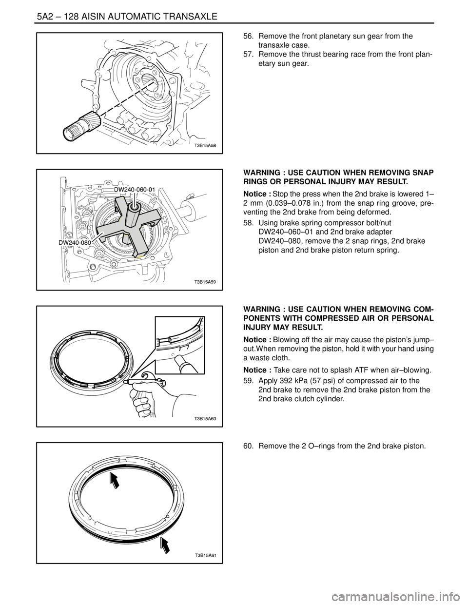
56. Remove the front planetary sun gear from the
transaxle case.
57. Remove the thrust bearing race from the front plan-
etary sun gear.
WARNING : USE CAUTION WHEN REMOVING SNAP
RINGS OR PERSONAL INJURY MAY RESULT.
Notice : Stop the press when the 2nd brake is lowered 1–
2 mm (0.039–0.078 in.) from the snap ring groove, pre-
venting the 2nd brake from being deformed.
58. Using brake spring compressor bolt/nut
DW240–060–01 and 2nd brake adapter
DW240–080, remove the 2 snap rings, 2nd brake
piston and 2nd brake piston return spring.
WARNING : USE CAUTION WHEN REMOVING COM-
PONENTS WITH COMPRESSED AIR OR PERSONAL
INJURY MAY RESULT.
Notice : Blowing off the air may cause the piston’s jump–
out.When removing the piston, hold it with your hand using
a waste cloth.
Notice : Take care not to splash ATF when air–blowing.
59. Apply 392 kPa (57 psi) of compressed air to the
2nd brake to remove the 2nd brake piston from the
2nd brake clutch cylinder.
60. Remove the 2 O–rings from the 2nd brake piston.
Page 1722 of 2643
5A2 – 132IAISIN AUTOMATIC TRANSAXLE
DAEWOO V–121 BL4
73. Using a screwdriver, remove the oil seal.
74. Using brake spring compressor bolt/nut
DW240–060–01, 1st & reverse brake adapter
DW240–070 and planetary ring gear remover
DW240–090, remove the planetary ring gear.
75. Install the 3 bolts to the counter drive gear.
S Bolt (M6) : L= 40–80mm, Pich = 1.0mm
76. Rotate 3 bolts in order and remove the counter
drive gear and planetary ring gear.
WARNING : USE CAUTION WHEN REMOVING SNAP
RINGS OR PERSONAL INJURY MAY RESULT.
77. Using brake spring compressor bolt/nut
DW240–060–01 and 1st & reverse brake adapter
DW240–070, remove the snap ring of 1st & reverse
brake.
Page 1723 of 2643
AISIN AUTOMATIC TRANSAXLE 5A2 – 133
DAEWOO V–121 BL4
78. Remove the flange, 4 discs, 4 plates and return
spring.
WARNING : USE CAUTION WHEN REMOVING COM-
PONENTS WITH COMPRESSED AIR OR PERSONAL
INJURY MAY RESULT.
Notice : Blowing off the air may cause the piston’s jump–
out. When removing the piston, hold it with your hand us-
ing a waste cloth.
Notice : Take care not to splash ATF when air–blowing
79. Apply 392 kPa (57 psi) of compressed air to the
transaxle case to remove the 1st & reverse brake
piston.
80. Remove the 2 O–rings from the 1st & reverse
brake piston.
81. Remove the bolt and No.1 transaxle case plate
from the transaxle case.
Page 1725 of 2643
AISIN AUTOMATIC TRANSAXLE 5A2 – 135
DAEWOO V–121 BL4
88. Using a suitable puller, remove the counter driven
gear outer tapered roller bearing race from the
transaxle housing.
89. Using a driver, remove the oil seal from the trans-
axle housing.
Notice : Be careful not to damage the transaxle housing
when removing the oil seal using a driver.
90. Using a suitable puller, remove the side bearing
outer race from the transaxle housing.
WARNING : USE CAUTION WHEN REMOVING SNAP
RINGS OR PERSONAL INJURY MAY RESULT.
Notice : Stop the press when the O/D brake piston is low-
ered 1–2 mm (0.039–0.078 in.) from the snap ring groove,
preventing the O/D brake piston from being deformed.
91. Using brake/clutch spring compressor DW240–020,
overdrive brake adapter DW240–050 and a driver,
remove the snap ring.
92. Remove the O/D brake return spring.
Page 1726 of 2643
5A2 – 136IAISIN AUTOMATIC TRANSAXLE
DAEWOO V–121 BL4
WARNING : USE CAUTION WHEN REMOVING COM-
PONENTS WITH COMPRESSED AIR OR PERSONAL
INJURY MAY RESULT.
Notice : Blowing off the air may cause the piston’s jump–
out.When removing the piston, hold it with your hand using
a waste cloth.
Notice : Take care not to splash ATF when air–blowing.
93. Apply 392 kPa (57 psi) of compressed air to the
transaxle rear cover to remove the O/D brake pis-
ton.
94. Remove the 2 O–rings from the O/D brake piston.
95. Remove the 2 seal rings from the transaxle rear
cover.
Notice : Do not expand the seal ring excessively.
96. Remove the 4 screw plugs and 4 O–rings from the
transaxle rear cover.
Page 1762 of 2643

5A2 – 172IAISIN AUTOMATIC TRANSAXLE
DAEWOO V–121 BL4
Tools Required
DW240–020 Brake/Clutch Spring Compressor
DW240–040 Direct Clutch Adapter
Disassembly Procedure
WARNING : USE CAUTION WHEN CHECKING COM-
PONENTS WITH COMPRESSED AIR OR PERSONAL
INJURY MAY RESULT.
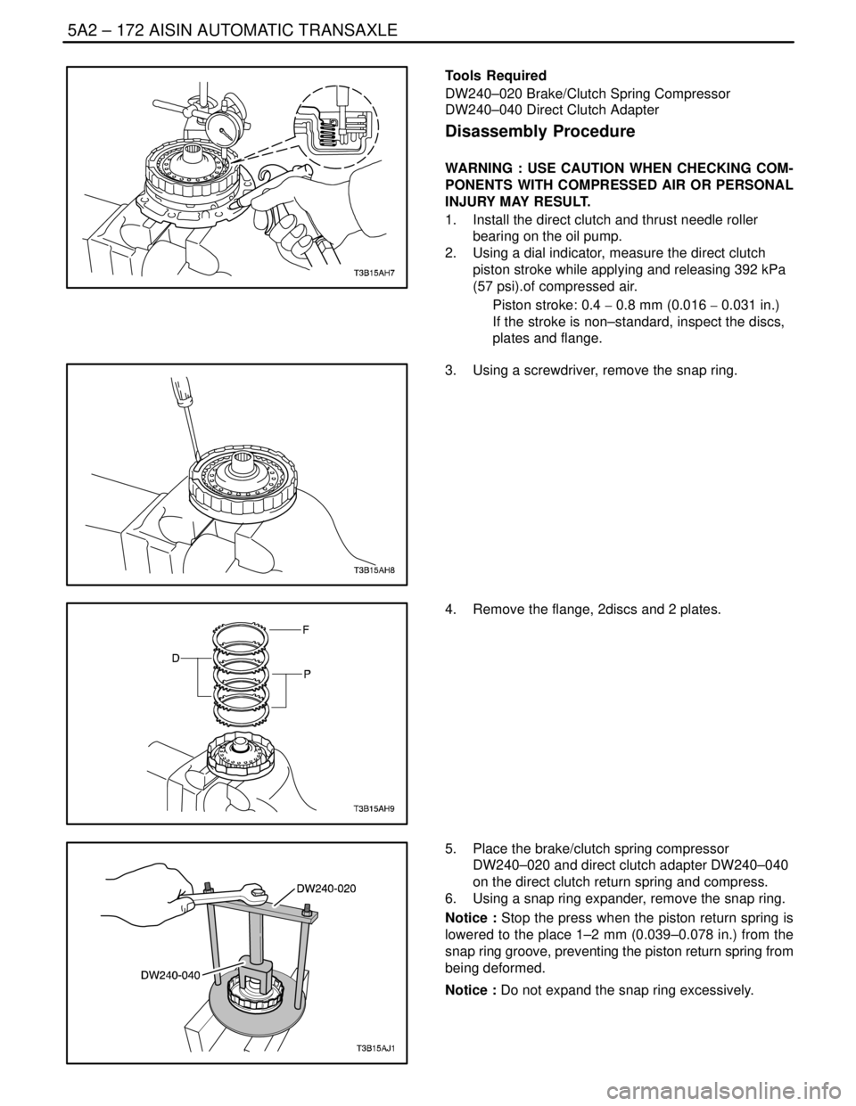
1. Install the direct clutch and thrust needle roller
bearing on the oil pump.
2. Using a dial indicator, measure the direct clutch
piston stroke while applying and releasing 392 kPa
(57 psi).of compressed air.
Piston stroke: 0.4 � 0.8 mm (0.016 � 0.031 in.)
If the stroke is non–standard, inspect the discs,
plates and flange.
3. Using a screwdriver, remove the snap ring.
4. Remove the flange, 2discs and 2 plates.
5. Place the brake/clutch spring compressor
DW240–020 and direct clutch adapter DW240–040
on the direct clutch return spring and compress.
6. Using a snap ring expander, remove the snap ring.
Notice : Stop the press when the piston return spring is
lowered to the place 1–2 mm (0.039–0.078 in.) from the
snap ring groove, preventing the piston return spring from
being deformed.
Notice : Do not expand the snap ring excessively.
Page 1763 of 2643
AISIN AUTOMATIC TRANSAXLE 5A2 – 173
DAEWOO V–121 BL4
7. Remove the direct clutch return spring.
8. Install the direct clutch on the oil pump.
WARNING : USE CAUTION WHEN REMOVING COM-
PONENTS WITH COMPRESSED AIR OR PERSONAL
INJURY MAY RESULT.
Notice : Blowing off the air may cause the piston’jump–
out.When removing the piston, hold it with your hand using
a waste cloth.
Notice : Take care not to splash ATF when air–blowing.
9. Apply 392 kPa (57 psi) of compressed air to the oil
pump to remove the direct clutch piston.
S When the piston can not be removed as it is
slanted, either blow the air again with the pro-
truding side pushed or remove the piston using
needle nose pliers with vinyl tape on the tip.
10. Using a small screwdriver, remove the O–ring from
the direct clutch piston.
11. Remove the O–ring from the input shaft.