Page 99 of 2643
1C1 – 56I1.4L/1.6L DOHC ENGINE MECHANICAL
DAEWOO V–121 BL4
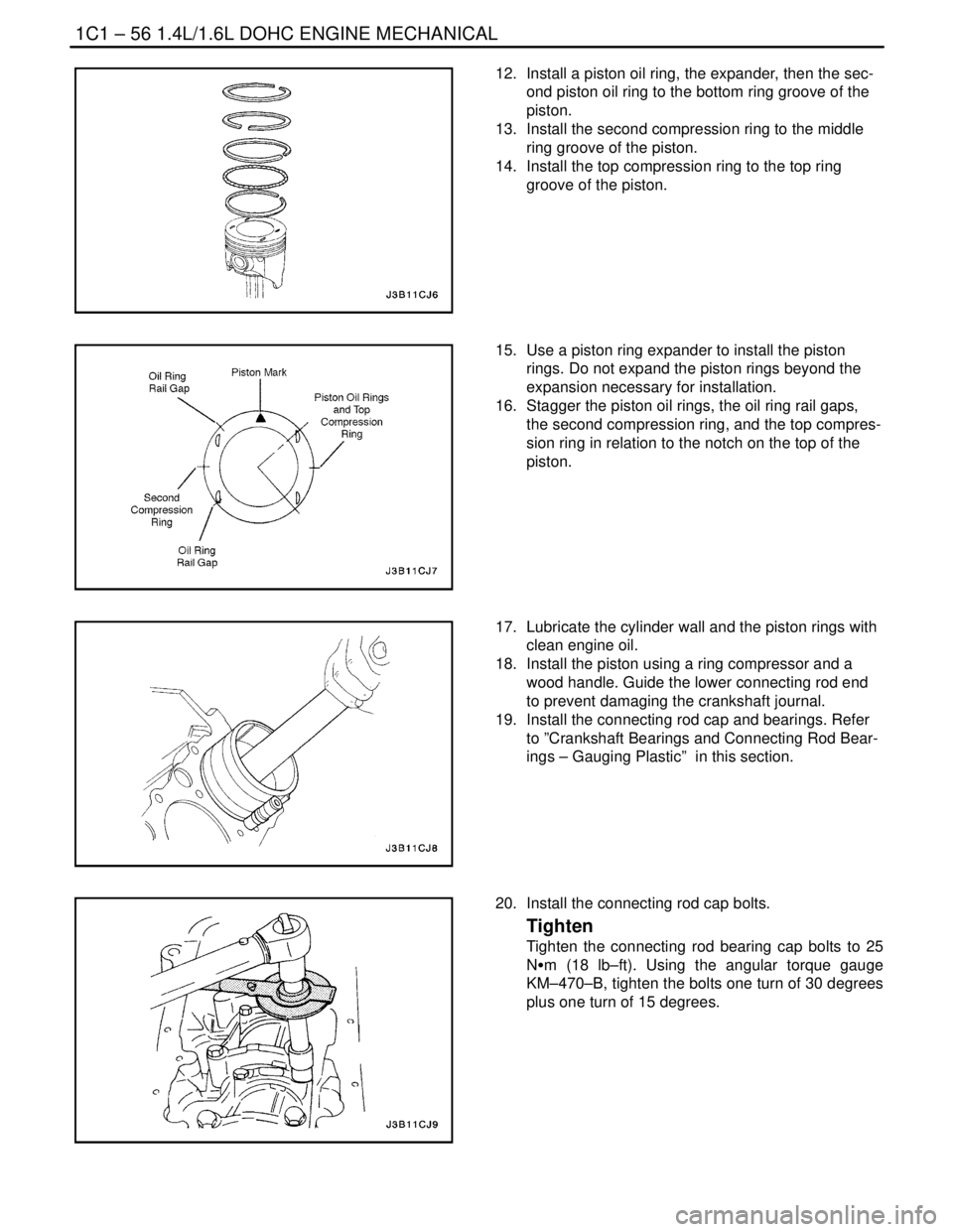
12. Install a piston oil ring, the expander, then the sec-
ond piston oil ring to the bottom ring groove of the
piston.
13. Install the second compression ring to the middle
ring groove of the piston.
14. Install the top compression ring to the top ring
groove of the piston.
15. Use a piston ring expander to install the piston
rings. Do not expand the piston rings beyond the
expansion necessary for installation.
16. Stagger the piston oil rings, the oil ring rail gaps,
the second compression ring, and the top compres-
sion ring in relation to the notch on the top of the
piston.
17. Lubricate the cylinder wall and the piston rings with
clean engine oil.
18. Install the piston using a ring compressor and a
wood handle. Guide the lower connecting rod end
to prevent damaging the crankshaft journal.
19. Install the connecting rod cap and bearings. Refer
to ”Crankshaft Bearings and Connecting Rod Bear-
ings – Gauging Plastic” in this section.
20. Install the connecting rod cap bolts.
Tighten
Tighten the connecting rod bearing cap bolts to 25
NSm (18 lb–ft). Using the angular torque gauge
KM–470–B, tighten the bolts one turn of 30 degrees
plus one turn of 15 degrees.
Page 100 of 2643
1.4L/1.6L DOHC ENGINE MECHANICAL 1C1 – 57
DAEWOO V–121 BL4
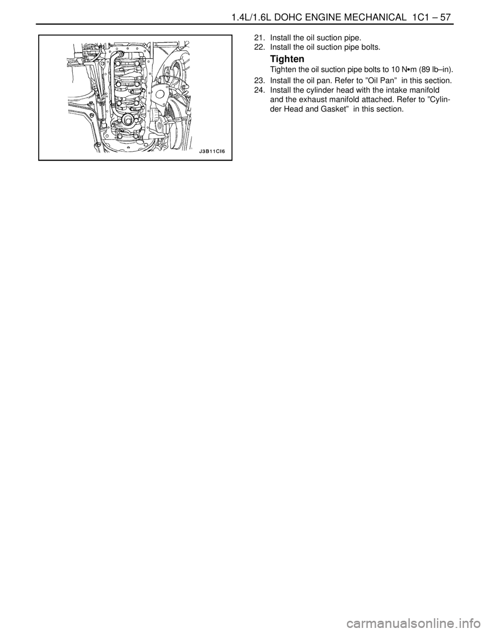
21. Install the oil suction pipe.
22. Install the oil suction pipe bolts.
Tighten
Tighten the oil suction pipe bolts to 10 NSm (89 lb–in).
23. Install the oil pan. Refer to ”Oil Pan” in this section.
24. Install the cylinder head with the intake manifold
and the exhaust manifold attached. Refer to ”Cylin-
der Head and Gasket” in this section.
Page 102 of 2643
1.4L/1.6L DOHC ENGINE MECHANICAL 1C1 – 59
DAEWOO V–121 BL4
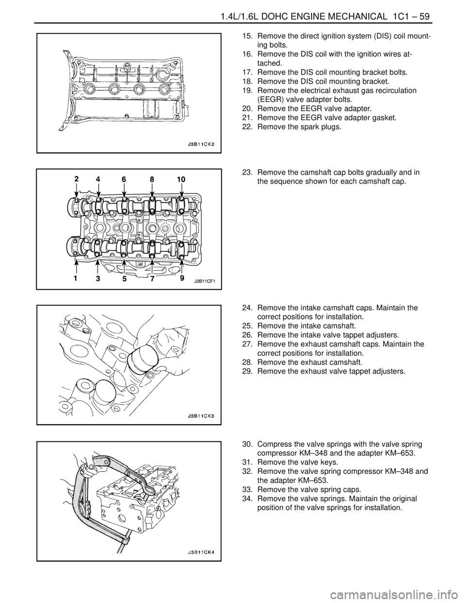
15. Remove the direct ignition system (DIS) coil mount-
ing bolts.
16. Remove the DIS coil with the ignition wires at-
tached.
17. Remove the DIS coil mounting bracket bolts.
18. Remove the DIS coil mounting bracket.
19. Remove the electrical exhaust gas recirculation
(EEGR) valve adapter bolts.
20. Remove the EEGR valve adapter.
21. Remove the EEGR valve adapter gasket.
22. Remove the spark plugs.
23. Remove the camshaft cap bolts gradually and in
the sequence shown for each camshaft cap.
24. Remove the intake camshaft caps. Maintain the
correct positions for installation.
25. Remove the intake camshaft.
26. Remove the intake valve tappet adjusters.
27. Remove the exhaust camshaft caps. Maintain the
correct positions for installation.
28. Remove the exhaust camshaft.
29. Remove the exhaust valve tappet adjusters.
30. Compress the valve springs with the valve spring
compressor KM–348 and the adapter KM–653.
31. Remove the valve keys.
32. Remove the valve spring compressor KM–348 and
the adapter KM–653.
33. Remove the valve spring caps.
34. Remove the valve springs. Maintain the original
position of the valve springs for installation.
Page 103 of 2643
1C1 – 60I1.4L/1.6L DOHC ENGINE MECHANICAL
DAEWOO V–121 BL4
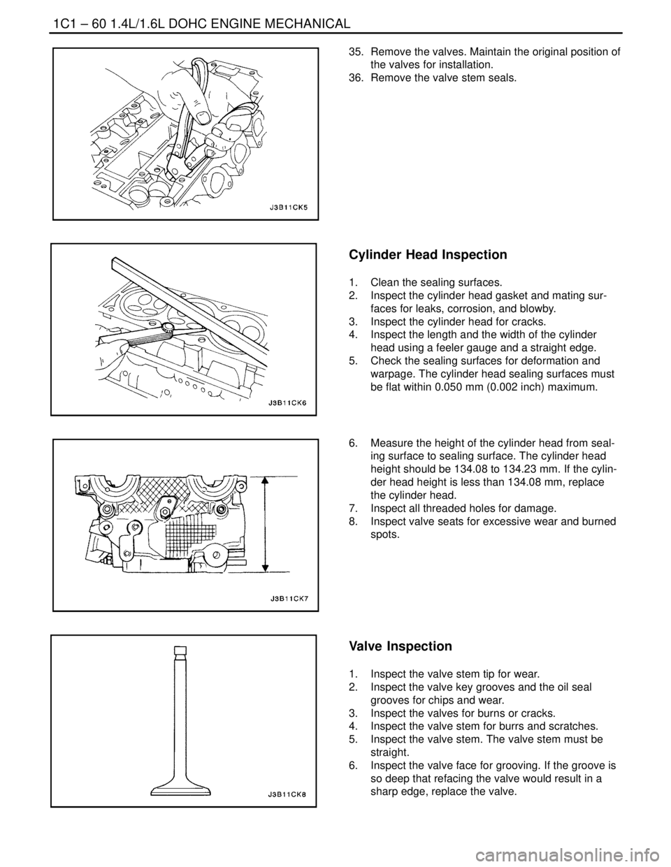
35. Remove the valves. Maintain the original position of
the valves for installation.
36. Remove the valve stem seals.
Cylinder Head Inspection
1. Clean the sealing surfaces.
2. Inspect the cylinder head gasket and mating sur-
faces for leaks, corrosion, and blowby.
3. Inspect the cylinder head for cracks.
4. Inspect the length and the width of the cylinder
head using a feeler gauge and a straight edge.
5. Check the sealing surfaces for deformation and
warpage. The cylinder head sealing surfaces must
be flat within 0.050 mm (0.002 inch) maximum.
6. Measure the height of the cylinder head from seal-
ing surface to sealing surface. The cylinder head
height should be 134.08 to 134.23 mm. If the cylin-
der head height is less than 134.08 mm, replace
the cylinder head.
7. Inspect all threaded holes for damage.
8. Inspect valve seats for excessive wear and burned
spots.
Valve Inspection
1. Inspect the valve stem tip for wear.
2. Inspect the valve key grooves and the oil seal
grooves for chips and wear.
3. Inspect the valves for burns or cracks.
4. Inspect the valve stem for burrs and scratches.
5. Inspect the valve stem. The valve stem must be
straight.
6. Inspect the valve face for grooving. If the groove is
so deep that refacing the valve would result in a
sharp edge, replace the valve.
Page 104 of 2643
1.4L/1.6L DOHC ENGINE MECHANICAL 1C1 – 61
DAEWOO V–121 BL4
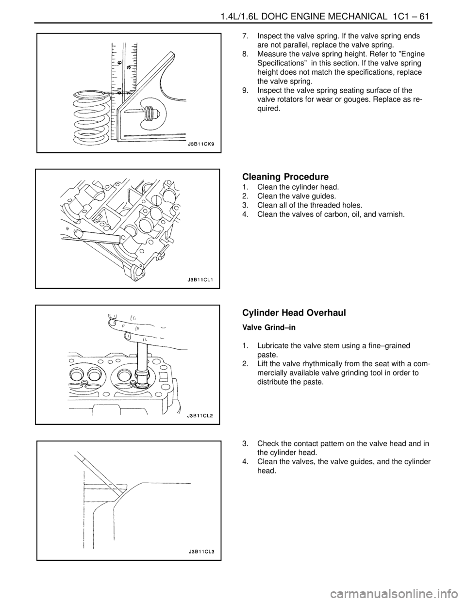
7. Inspect the valve spring. If the valve spring ends
are not parallel, replace the valve spring.
8. Measure the valve spring height. Refer to ”Engine
Specifications” in this section. If the valve spring
height does not match the specifications, replace
the valve spring.
9. Inspect the valve spring seating surface of the
valve rotators for wear or gouges. Replace as re-
quired.
Cleaning Procedure
1. Clean the cylinder head.
2. Clean the valve guides.
3. Clean all of the threaded holes.
4. Clean the valves of carbon, oil, and varnish.
Cylinder Head Overhaul
Valve Grind–in
1. Lubricate the valve stem using a fine–grained
paste.
2. Lift the valve rhythmically from the seat with a com-
mercially available valve grinding tool in order to
distribute the paste.
3. Check the contact pattern on the valve head and in
the cylinder head.
4. Clean the valves, the valve guides, and the cylinder
head.
Page 106 of 2643
1.4L/1.6L DOHC ENGINE MECHANICAL 1C1 – 63
DAEWOO V–121 BL4
4. Inspect the dimension for the valve seat width.
S Intake: 1.17 to 1.57 mm (0.046 to 0.062 inch).
S Exhaust: 1.4 to 1.8 mm (0.055 to 0.071 inch).
5. Inspect the assembly height of the intake valves
and the exhaust valves. If the dimension is exceed-
ed, install new valves. Inspect the assembly height
of the intake valves and the exhaust valves again. If
the valve assembly height is still too large despite
replacing the valves, replace the cylinder head.
Assembly Procedure
1. Install the valve stem seals.
2. Lubricate the valve stems with engine oil.
3. Carefully install the valves in their original positions.
Do not damage the valve stem seals.
4. Install the valve springs in their original positions.
5. Install the valve spring caps.
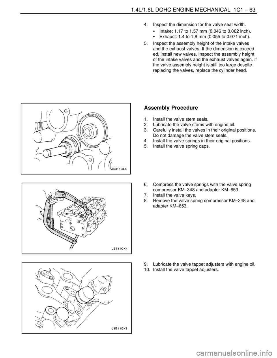
6. Compress the valve springs with the valve spring
compressor KM–348 and adapter KM–653.
7. Install the valve keys.
8. Remove the valve spring compressor KM–348 and
adapter KM–653.
9. Lubricate the valve tappet adjusters with engine oil.
10. Install the valve tappet adjusters.
Page 107 of 2643
1C1 – 64I1.4L/1.6L DOHC ENGINE MECHANICAL
DAEWOO V–121 BL4
11. Install the intake camshaft.
12. Install the intake camshaft caps in their original
positions.
13. Install the exhaust camshaft.
14. Install the exhaust camshaft caps in their original
positions.
15. Install the camshaft cap bolts.
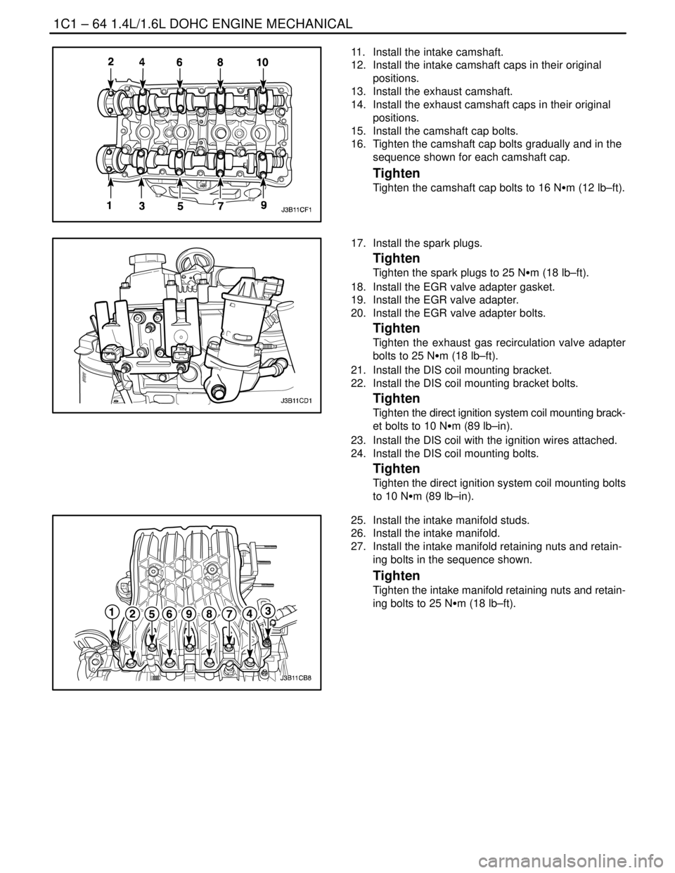
16. Tighten the camshaft cap bolts gradually and in the
sequence shown for each camshaft cap.
Tighten
Tighten the camshaft cap bolts to 16 NSm (12 lb–ft).
17. Install the spark plugs.
Tighten
Tighten the spark plugs to 25 NSm (18 lb–ft).
18. Install the EGR valve adapter gasket.
19. Install the EGR valve adapter.
20. Install the EGR valve adapter bolts.
Tighten
Tighten the exhaust gas recirculation valve adapter
bolts to 25 NSm (18 lb–ft).
21. Install the DIS coil mounting bracket.
22. Install the DIS coil mounting bracket bolts.
Tighten
Tighten the direct ignition system coil mounting brack-
et bolts to 10 NSm (89 lb–in).
23. Install the DIS coil with the ignition wires attached.
24. Install the DIS coil mounting bolts.
Tighten
Tighten the direct ignition system coil mounting bolts
to 10 NSm (89 lb–in).
25. Install the intake manifold studs.
26. Install the intake manifold.
27. Install the intake manifold retaining nuts and retain-
ing bolts in the sequence shown.
Tighten
Tighten the intake manifold retaining nuts and retain-
ing bolts to 25 NSm (18 lb–ft).
Page 108 of 2643
1.4L/1.6L DOHC ENGINE MECHANICAL 1C1 – 65
DAEWOO V–121 BL4
28. Install the fuel rail assembly with the bolts.
Tighten
Tighten the fuel rail assembly retaining bolts to 25
NSm (18 lb–ft).
29. Install the thermostat housing assembly.
30. Install the thermostat housing mounting bolts.
Tighten
Tighten the thermostat housing mounting bolts to 20
NSm (15 lb–ft).
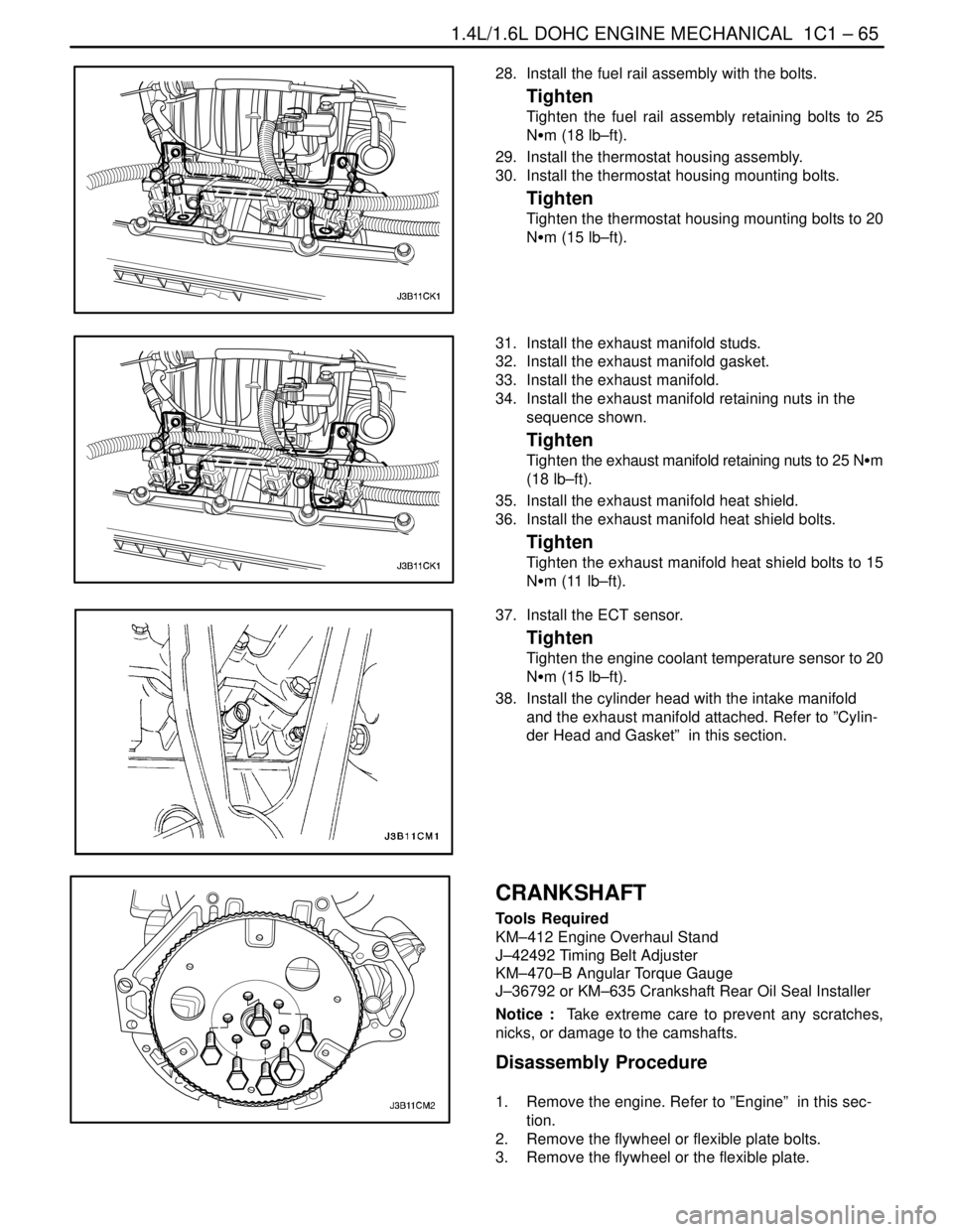
31. Install the exhaust manifold studs.
32. Install the exhaust manifold gasket.
33. Install the exhaust manifold.
34. Install the exhaust manifold retaining nuts in the
sequence shown.
Tighten
Tighten the exhaust manifold retaining nuts to 25 NSm
(18 lb–ft).
35. Install the exhaust manifold heat shield.
36. Install the exhaust manifold heat shield bolts.
Tighten
Tighten the exhaust manifold heat shield bolts to 15
NSm (11 lb–ft).
37. Install the ECT sensor.
Tighten
Tighten the engine coolant temperature sensor to 20
NSm (15 lb–ft).
38. Install the cylinder head with the intake manifold
and the exhaust manifold attached. Refer to ”Cylin-
der Head and Gasket” in this section.
CRANKSHAFT
Tools Required
KM–412 Engine Overhaul Stand
J–42492 Timing Belt Adjuster
KM–470–B Angular Torque Gauge
J–36792 or KM–635 Crankshaft Rear Oil Seal Installer
Notice : Take extreme care to prevent any scratches,
nicks, or damage to the camshafts.
Disassembly Procedure
1. Remove the engine. Refer to ”Engine” in this sec-
tion.
2. Remove the flywheel or flexible plate bolts.
3. Remove the flywheel or the flexible plate.