Page 77 of 2643
1C1 – 34I1.4L/1.6L DOHC ENGINE MECHANICAL
DAEWOO V–121 BL4
37. Connect the air cleaner outlet hose to the throttle
body.
38. Connect the breather tube to the camshaft cover.
39. Connect the negative battery cable.
TIMING BELT
Tools Required
J–42492 Timing Belt Adjuster
KM–470–B Angular Torque Gauge
Removal Procedure
1. Disconnect the negative battery cable.
2. Disconnect the air cleaner outlet hose from the
throttle body.
3. Disconnect the breather tube from the camshaft
cover.
4. Remove the air cleaner housing bolts.
5. Remove the air cleaner housing.
6. Remove the right front wheel. Refer to Section 2E,
Tires and Wheels.
7. Remove the right front wheel well splash shield.
8. Remove the serpentine accessory drive belt. Refer
to Section 6B, Power Steering Pump.
9. Remove the crankshaft pulley bolt.
10. Remove the crankshaft pulley.
Page 78 of 2643
1.4L/1.6L DOHC ENGINE MECHANICAL 1C1 – 35
DAEWOO V–121 BL4
11. Remove the upper front timing belt cover bolts.
12. Remove the upper front timing belt cover.
13. Remove the lower front timing belt cover bolts.
14. Remove the lower front timing belt cover.
15. Install the crankshaft pulley bolt.
16. Using the crankshaft pulley bolt, rotate the crank-
shaft clockwise until the timing mark on the crank-
shaft gear is aligned with the notch at the bottom of
the rear timing belt cover.
17. Slightly loosen the water pump retaining bolts.
18. Using the timing belt adjuster J–42492, rotate the
water pump counterclockwise to release the tension
on the timing belt.
19. Remove the right engine mount bracket. Refer to
”Engine Mount” in this section.
20. Remove the timing belt.
Page 79 of 2643
1C1 – 36I1.4L/1.6L DOHC ENGINE MECHANICAL
DAEWOO V–121 BL4
Installation Procedure
1. Align the timing mark on the crankshaft gear with
the notch on the bottom of the rear timing belt cov-
er.
2. Align the timing marks on the camshaft gears.
3. Install the timing belt.
4. Install the right engine mount bracket. Refer to ”En-
gine Mount” in this section.
5. Rotate the water pump clockwise using the timing
belt adjuster J–42492.
6. Rotate the water pump clockwise until the adjust
arm pointer of the timing belt automatic tensioner is
aligned with the notch in the timing belt automatic
tensioner bracket.
7. Tighten the water pump retaining bolts.
8. Rotate the crankshaft two full turns clockwise using
the crankshaft pulley bolt.
9. Loosen the water pump retaining bolts.
10. Rotate the water pump until the adjust arm pointer
of the timing belt automatic tensioner is aligned with
the pointer on the timing belt automatic tensioner
bracket.
Page 80 of 2643

1.4L/1.6L DOHC ENGINE MECHANICAL 1C1 – 37
DAEWOO V–121 BL4
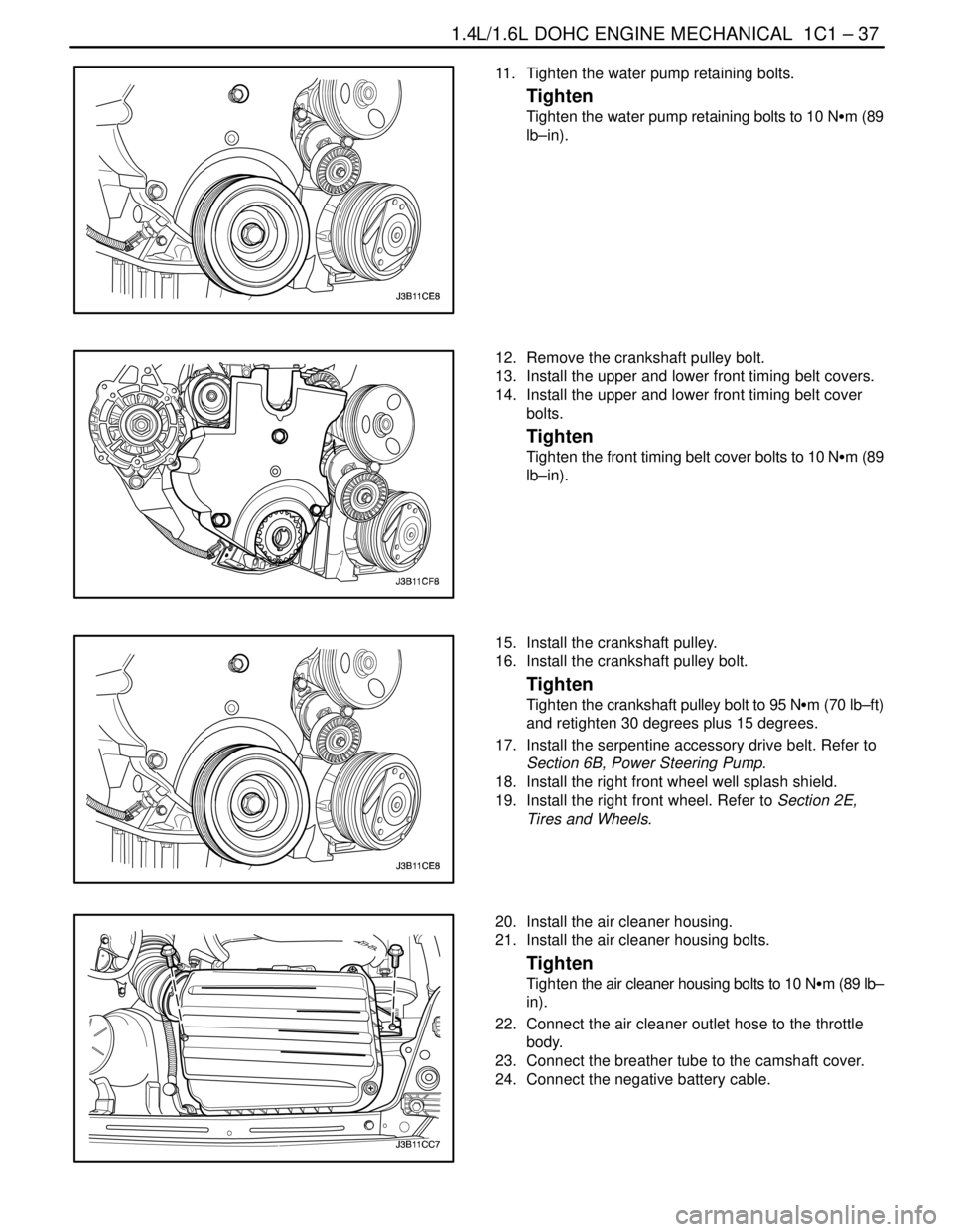
11. Tighten the water pump retaining bolts.
Tighten
Tighten the water pump retaining bolts to 10 NSm (89
lb–in).
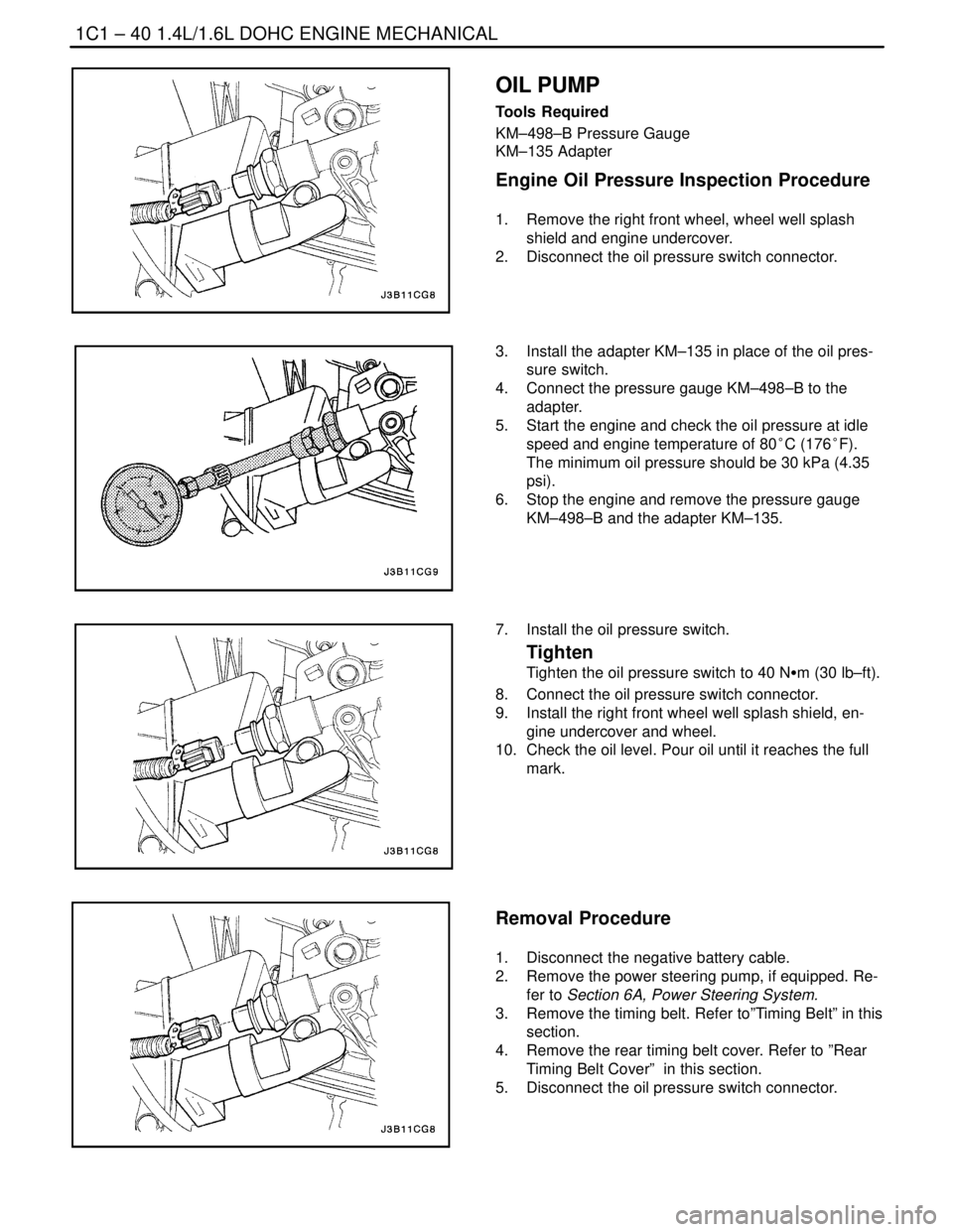
12. Remove the crankshaft pulley bolt.
13. Install the upper and lower front timing belt covers.
14. Install the upper and lower front timing belt cover
bolts.
Tighten
Tighten the front timing belt cover bolts to 10 NSm (89
lb–in).
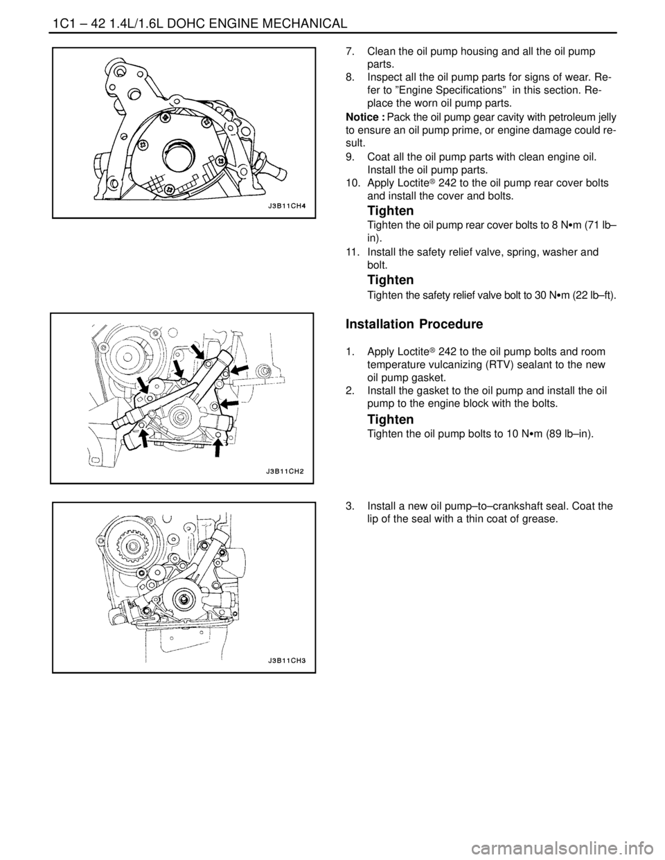
15. Install the crankshaft pulley.
16. Install the crankshaft pulley bolt.
Tighten
Tighten the crankshaft pulley bolt to 95 NSm (70 lb–ft)
and retighten 30 degrees plus 15 degrees.
17. Install the serpentine accessory drive belt. Refer to
Section 6B, Power Steering Pump.
18. Install the right front wheel well splash shield.
19. Install the right front wheel. Refer to Section 2E,
Tires and Wheels.
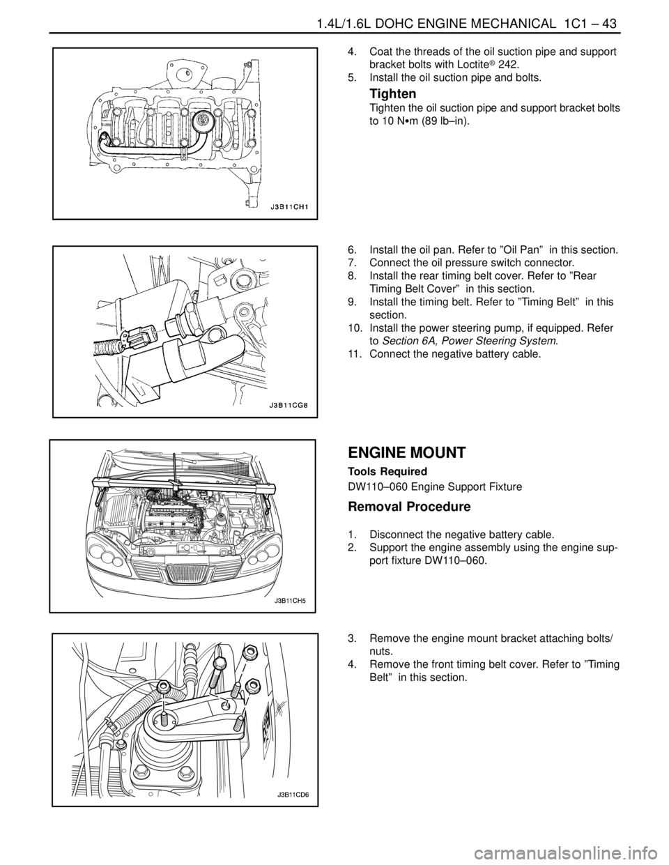
20. Install the air cleaner housing.
21. Install the air cleaner housing bolts.
Tighten
Tighten the air cleaner housing bolts to 10 NSm (89 lb–
in).
22. Connect the air cleaner outlet hose to the throttle
body.
23. Connect the breather tube to the camshaft cover.
24. Connect the negative battery cable.
Page 83 of 2643

1C1 – 40I1.4L/1.6L DOHC ENGINE MECHANICAL
DAEWOO V–121 BL4
OIL PUMP
Tools Required
KM–498–B Pressure Gauge
KM–135 Adapter
Engine Oil Pressure Inspection Procedure
1. Remove the right front wheel, wheel well splash
shield and engine undercover.
2. Disconnect the oil pressure switch connector.
3. Install the adapter KM–135 in place of the oil pres-
sure switch.
4. Connect the pressure gauge KM–498–B to the
adapter.
5. Start the engine and check the oil pressure at idle
speed and engine temperature of 80°C (176°F).
The minimum oil pressure should be 30 kPa (4.35
psi).
6. Stop the engine and remove the pressure gauge
KM–498–B and the adapter KM–135.
7. Install the oil pressure switch.
Tighten
Tighten the oil pressure switch to 40 NSm (30 lb–ft).
8. Connect the oil pressure switch connector.
9. Install the right front wheel well splash shield, en-
gine undercover and wheel.
10. Check the oil level. Pour oil until it reaches the full
mark.
Removal Procedure
1. Disconnect the negative battery cable.
2. Remove the power steering pump, if equipped. Re-
fer to Section 6A, Power Steering System.
3. Remove the timing belt. Refer to”Timing Belt” in this
section.
4. Remove the rear timing belt cover. Refer to ”Rear
Timing Belt Cover” in this section.
5. Disconnect the oil pressure switch connector.
Page 85 of 2643

1C1 – 42I1.4L/1.6L DOHC ENGINE MECHANICAL
DAEWOO V–121 BL4
7. Clean the oil pump housing and all the oil pump
parts.
8. Inspect all the oil pump parts for signs of wear. Re-
fer to ”Engine Specifications” in this section. Re-
place the worn oil pump parts.
Notice : Pack the oil pump gear cavity with petroleum jelly
to ensure an oil pump prime, or engine damage could re-
sult.
9. Coat all the oil pump parts with clean engine oil.
Install the oil pump parts.
10. Apply Loctite® 242 to the oil pump rear cover bolts
and install the cover and bolts.
Tighten
Tighten the oil pump rear cover bolts to 8 NSm (71 lb–
in).
11. Install the safety relief valve, spring, washer and
bolt.
Tighten
Tighten the safety relief valve bolt to 30 NSm (22 lb–ft).
Installation Procedure
1. Apply Loctite® 242 to the oil pump bolts and room
temperature vulcanizing (RTV) sealant to the new
oil pump gasket.
2. Install the gasket to the oil pump and install the oil
pump to the engine block with the bolts.
Tighten
Tighten the oil pump bolts to 10 NSm (89 lb–in).
3. Install a new oil pump–to–crankshaft seal. Coat the
lip of the seal with a thin coat of grease.
Page 86 of 2643

1.4L/1.6L DOHC ENGINE MECHANICAL 1C1 – 43
DAEWOO V–121 BL4
4. Coat the threads of the oil suction pipe and support
bracket bolts with Loctite® 242.
5. Install the oil suction pipe and bolts.
Tighten
Tighten the oil suction pipe and support bracket bolts
to 10 NSm (89 lb–in).
6. Install the oil pan. Refer to ”Oil Pan” in this section.
7. Connect the oil pressure switch connector.
8. Install the rear timing belt cover. Refer to ”Rear
Timing Belt Cover” in this section.
9. Install the timing belt. Refer to ”Timing Belt” in this
section.
10. Install the power steering pump, if equipped. Refer
to Section 6A, Power Steering System.
11. Connect the negative battery cable.
ENGINE MOUNT
Tools Required
DW110–060 Engine Support Fixture
Removal Procedure
1. Disconnect the negative battery cable.
2. Support the engine assembly using the engine sup-
port fixture DW110–060.
3. Remove the engine mount bracket attaching bolts/
nuts.
4. Remove the front timing belt cover. Refer to ”Timing
Belt” in this section.
Page 87 of 2643
1C1 – 44I1.4L/1.6L DOHC ENGINE MECHANICAL
DAEWOO V–121 BL4
5. Remove the engine mount attaching bolts/nuts.
6. Remove the engine mount.
Installation Procedure
1. Install the engine mount.
2. Install the engine mount retaining bolts.
Tighten
Tighten the engine mount attaching bolts to 30 NSm
(22 lb–ft).
3. Install the front timing belt cover. Refer to ”Timing
Belt” in this section.
4. Install the engine mount bracket attaching bolts/
nuts.
Tighten
Tighten the engine mount bracket attaching bolts/
nuts to 55 NSm (41 lb–ft).
5. Remove engine assembly support fixture
DW110–060.
6. Connect the negative battery cable.