2004 DAEWOO LACETTI adding oil
[x] Cancel search: adding oilPage 2042 of 2643
7B – 40IMANUAL CONTROL HEATING, VENTILATION AND AIR CONDITIONING SYSTEM
DAEWOO V–121 BL4
11. Remove the compressor from the bench vise and
remove the J–34992 compressor holding fixture
from the compressor.
12. Install the compressor. Refer to ”Compressor” in
this section.
CLUTCH ROTOR AND BEARING
Tools Required
J–6083 Snap Ring Pliers
J–9398–A Bearing Remover
J–9481 Bearing Installer
J–33020 Pulley Puller
J–33023–A Puller Pilot
J–33019 Bearing Staking Tool Set
Includes: J–33019–1 Bearing Staking Guide
Includes: J–33019–2 Bearing Staking Pin
Includes: J–33019–1 Bearing Staking Guide
J–33017 Pulley Rotor and Bearing Installer
J–8433–1 Puller Crossbar
J–34992 Compressor Holding Fixture
J–8092 Driver Handle
J–8433–3 Forcing Screw
Disassembly Procedure
1. Disconnect the negative battery cable.
2. Recover the refrigerant. Refer to ”Discharging,
Adding Oil, Evacuating, and Charging for A/C Sys-
tem” in this section.
3. Remove the compressor. Refer to ”Compressor” in
this section.
4. Remove the clutch drive plate and hub assembly.
Refer to ”Clutch Plate and Hub Assembly” in this
section.
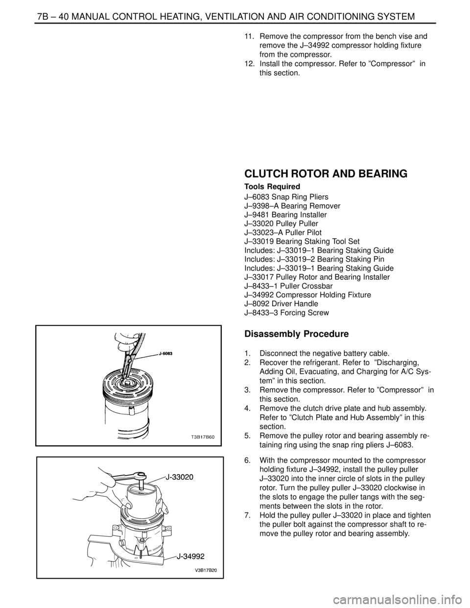
5. Remove the pulley rotor and bearing assembly re-
taining ring using the snap ring pliers J–6083.
6. With the compressor mounted to the compressor
holding fixture J–34992, install the pulley puller
J–33020 into the inner circle of slots in the pulley
rotor. Turn the pulley puller J–33020 clockwise in
the slots to engage the puller tangs with the seg-
ments between the slots in the rotor.
7. Hold the pulley puller J–33020 in place and tighten
the puller bolt against the compressor shaft to re-
move the pulley rotor and bearing assembly.
Page 2044 of 2643
7B – 42IMANUAL CONTROL HEATING, VENTILATION AND AIR CONDITIONING SYSTEM
DAEWOO V–121 BL4
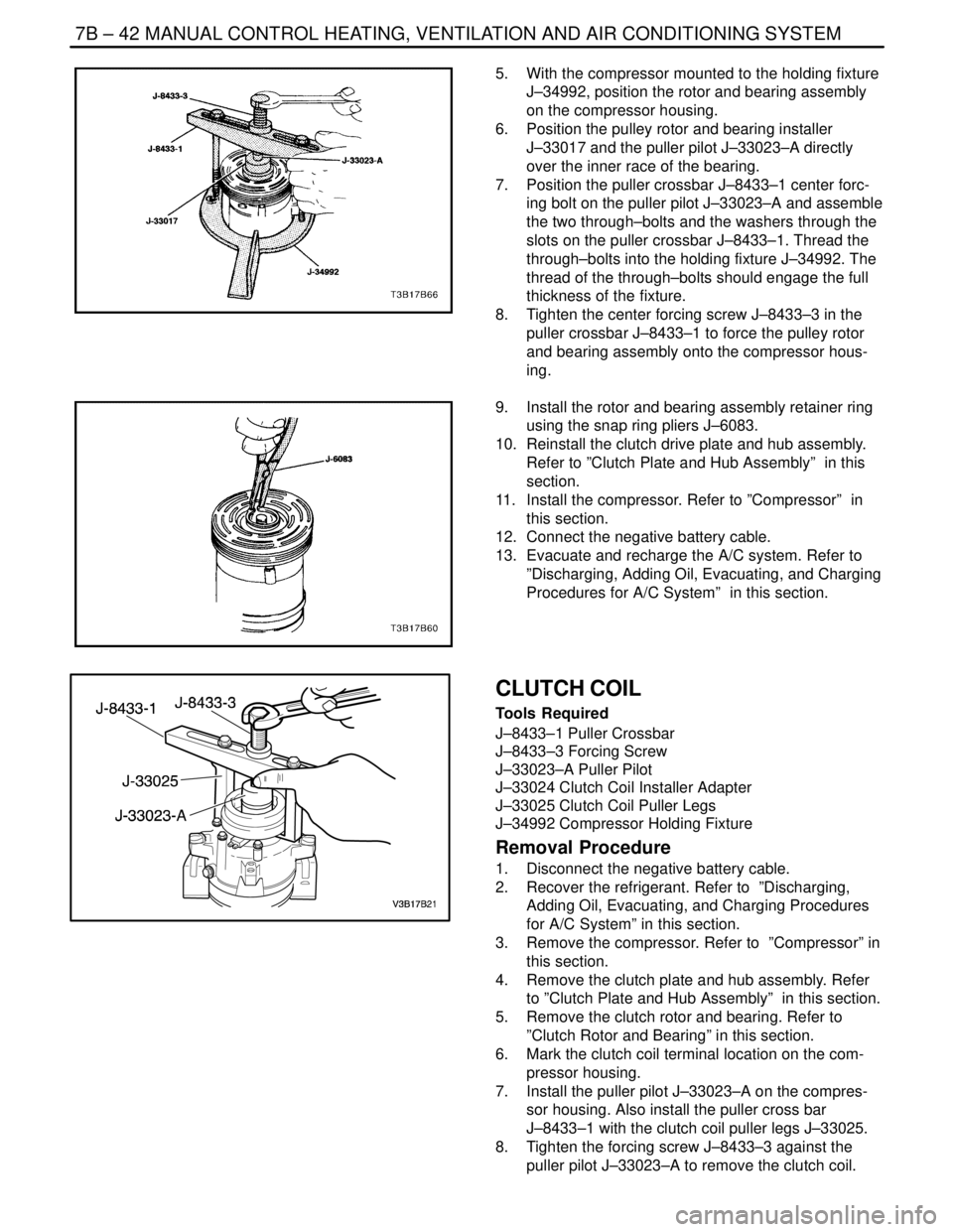
5. With the compressor mounted to the holding fixture
J–34992, position the rotor and bearing assembly
on the compressor housing.
6. Position the pulley rotor and bearing installer
J–33017 and the puller pilot J–33023–A directly
over the inner race of the bearing.
7. Position the puller crossbar J–8433–1 center forc-
ing bolt on the puller pilot J–33023–A and assemble
the two through–bolts and the washers through the
slots on the puller crossbar J–8433–1. Thread the
through–bolts into the holding fixture J–34992. The
thread of the through–bolts should engage the full
thickness of the fixture.
8. Tighten the center forcing screw J–8433–3 in the
puller crossbar J–8433–1 to force the pulley rotor
and bearing assembly onto the compressor hous-
ing.
9. Install the rotor and bearing assembly retainer ring
using the snap ring pliers J–6083.
10. Reinstall the clutch drive plate and hub assembly.
Refer to ”Clutch Plate and Hub Assembly” in this
section.
11. Install the compressor. Refer to ”Compressor” in
this section.
12. Connect the negative battery cable.
13. Evacuate and recharge the A/C system. Refer to
”Discharging, Adding Oil, Evacuating, and Charging
Procedures for A/C System” in this section.
CLUTCH COIL
Tools Required
J–8433–1 Puller Crossbar
J–8433–3 Forcing Screw
J–33023–A Puller Pilot
J–33024 Clutch Coil Installer Adapter
J–33025 Clutch Coil Puller Legs
J–34992 Compressor Holding Fixture
Removal Procedure
1. Disconnect the negative battery cable.
2. Recover the refrigerant. Refer to ”Discharging,
Adding Oil, Evacuating, and Charging Procedures
for A/C System” in this section.
3. Remove the compressor. Refer to ”Compressor” in
this section.
4. Remove the clutch plate and hub assembly. Refer
to ”Clutch Plate and Hub Assembly” in this section.
5. Remove the clutch rotor and bearing. Refer to
”Clutch Rotor and Bearing” in this section.
6. Mark the clutch coil terminal location on the com-
pressor housing.
7. Install the puller pilot J–33023–A on the compres-
sor housing. Also install the puller cross bar
J–8433–1 with the clutch coil puller legs J–33025.
8. Tighten the forcing screw J–8433–3 against the
puller pilot J–33023–A to remove the clutch coil.
Page 2045 of 2643
MANUAL CONTROL HEATING, VENTILATION AND AIR CONDITIONING SYSTEM 7B – 43
DAEWOO V–121 BL4
Installation Procedure
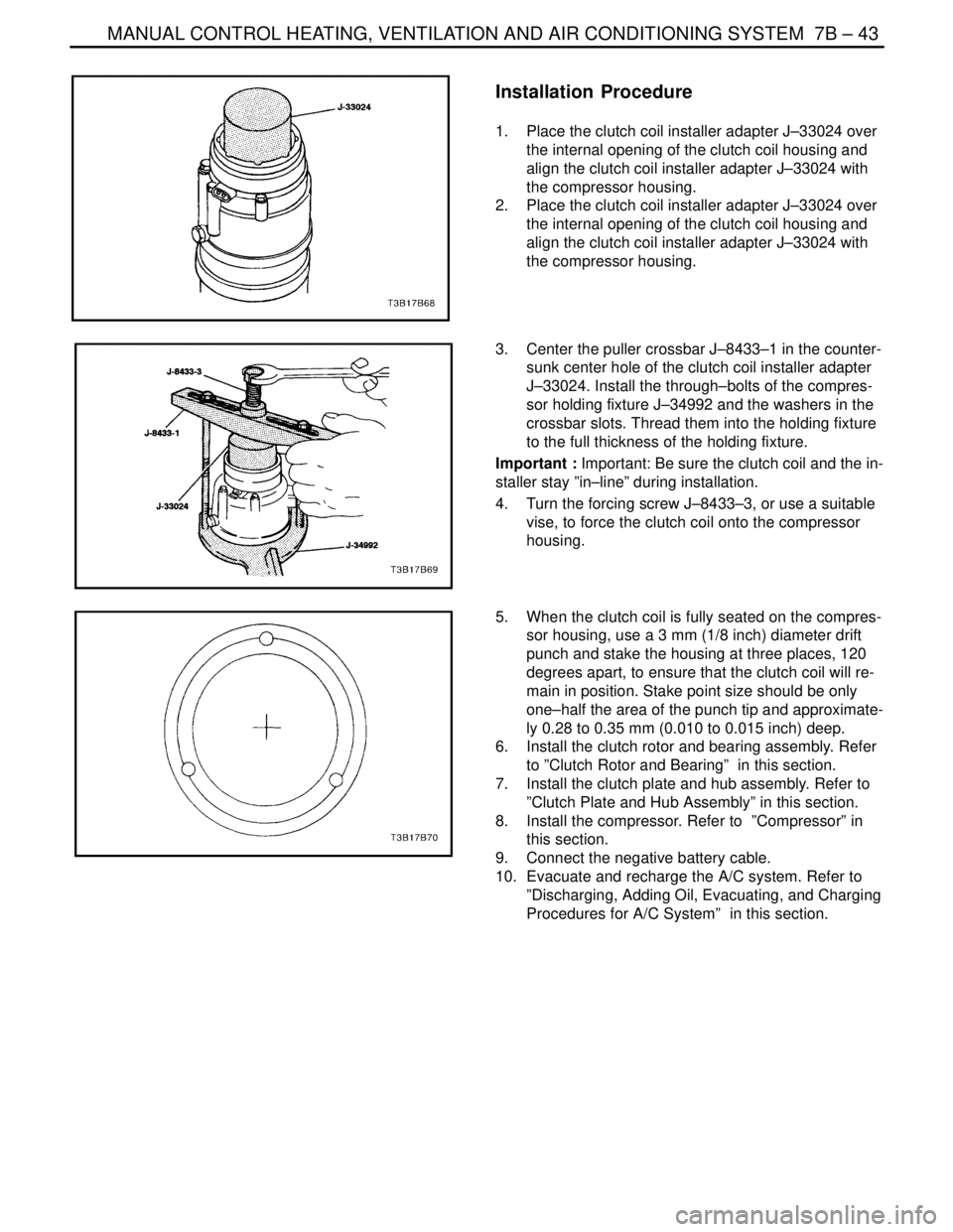
1. Place the clutch coil installer adapter J–33024 over
the internal opening of the clutch coil housing and
align the clutch coil installer adapter J–33024 with
the compressor housing.
2. Place the clutch coil installer adapter J–33024 over
the internal opening of the clutch coil housing and
align the clutch coil installer adapter J–33024 with
the compressor housing.
3. Center the puller crossbar J–8433–1 in the counter-
sunk center hole of the clutch coil installer adapter
J–33024. Install the through–bolts of the compres-
sor holding fixture J–34992 and the washers in the
crossbar slots. Thread them into the holding fixture
to the full thickness of the holding fixture.
Important : Important: Be sure the clutch coil and the in-
staller stay ”in–line” during installation.
4. Turn the forcing screw J–8433–3, or use a suitable
vise, to force the clutch coil onto the compressor
housing.
5. When the clutch coil is fully seated on the compres-
sor housing, use a 3 mm (1/8 inch) diameter drift
punch and stake the housing at three places, 120
degrees apart, to ensure that the clutch coil will re-
main in position. Stake point size should be only
one–half the area of the punch tip and approximate-
ly 0.28 to 0.35 mm (0.010 to 0.015 inch) deep.
6. Install the clutch rotor and bearing assembly. Refer
to ”Clutch Rotor and Bearing” in this section.
7. Install the clutch plate and hub assembly. Refer to
”Clutch Plate and Hub Assembly” in this section.
8. Install the compressor. Refer to ”Compressor” in
this section.
9. Connect the negative battery cable.
10. Evacuate and recharge the A/C system. Refer to
”Discharging, Adding Oil, Evacuating, and Charging
Procedures for A/C System” in this section.
Page 2046 of 2643
7B – 44IMANUAL CONTROL HEATING, VENTILATION AND AIR CONDITIONING SYSTEM
DAEWOO V–121 BL4
SHAFT SEAL REPLACEMENT
Tools Required
J–5403 Snap Ring Pliers
J–9553–1 O–Ring Remover
J–23128–A Seal Seat Remover/Installer
J–33011 O–Ring Installer
J–34614 Shaft Seal Protector
Important : A shaft seal should not be replaced because
a small amount of oil is found on the adjacent surface. The
seal is designed to leak some oil for lubrication purposes.
A shaft seal should be changed only when a large amount
of sprayed oil is found and then only after actual refrigerant
leakage is found by using an approved leak detection pro-
cedure. Refer to ”Leak Testing the Refrigerant System” in
this section.
Should a compressor shaft seal ever have to be replaced,
the receiver–dryer in this system must also be removed
from the vehicle. The oil in the receiver–dryer must then
be drained, measured and replaced. Refer to ”Discharg-
ing, Adding Oil, Evacuating, and Charging Procedures for
A/C System” in this section.
Removal Procedure
1. Disconnect the negative battery cable.
2. Recover the refrigerant. Refer to ”Discharging, Add-
ing Oil, Evacuating, and Charging Procedures for
A/C System” in this section.
3. Loosen and reposition the compressor in the
mounting brackets.
4. Remove the clutch drive plate and hub assembly
from the compressor. Refer to ”Clutch Plate and
Hub Assembly” in this section.
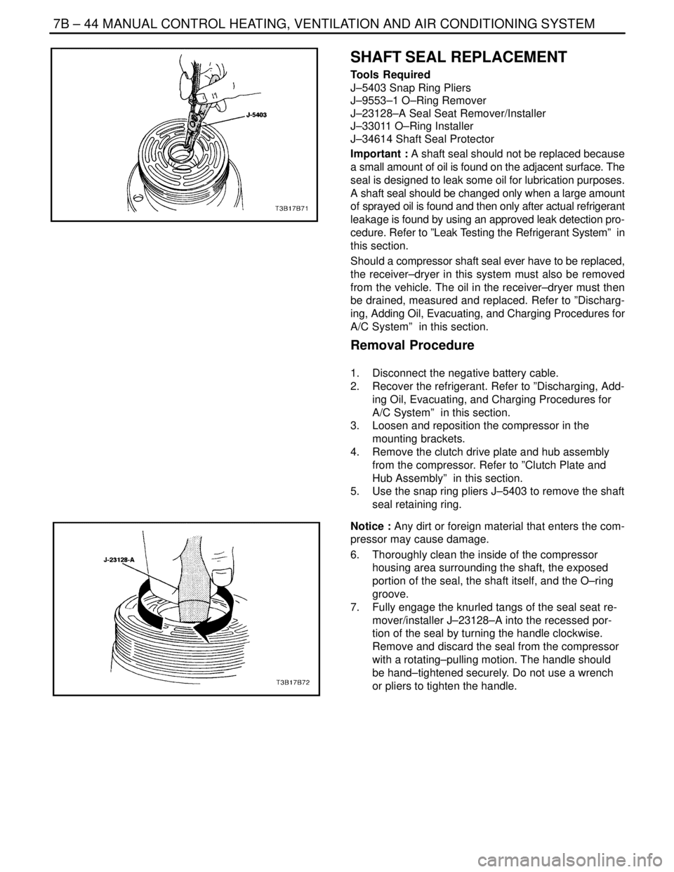
5. Use the snap ring pliers J–5403 to remove the shaft
seal retaining ring.
Notice : Any dirt or foreign material that enters the com-
pressor may cause damage.
6. Thoroughly clean the inside of the compressor
housing area surrounding the shaft, the exposed
portion of the seal, the shaft itself, and the O–ring
groove.
7. Fully engage the knurled tangs of the seal seat re-
mover/installer J–23128–A into the recessed por-
tion of the seal by turning the handle clockwise.
Remove and discard the seal from the compressor
with a rotating–pulling motion. The handle should
be hand–tightened securely. Do not use a wrench
or pliers to tighten the handle.
Page 2048 of 2643
7B – 46IMANUAL CONTROL HEATING, VENTILATION AND AIR CONDITIONING SYSTEM
DAEWOO V–121 BL4
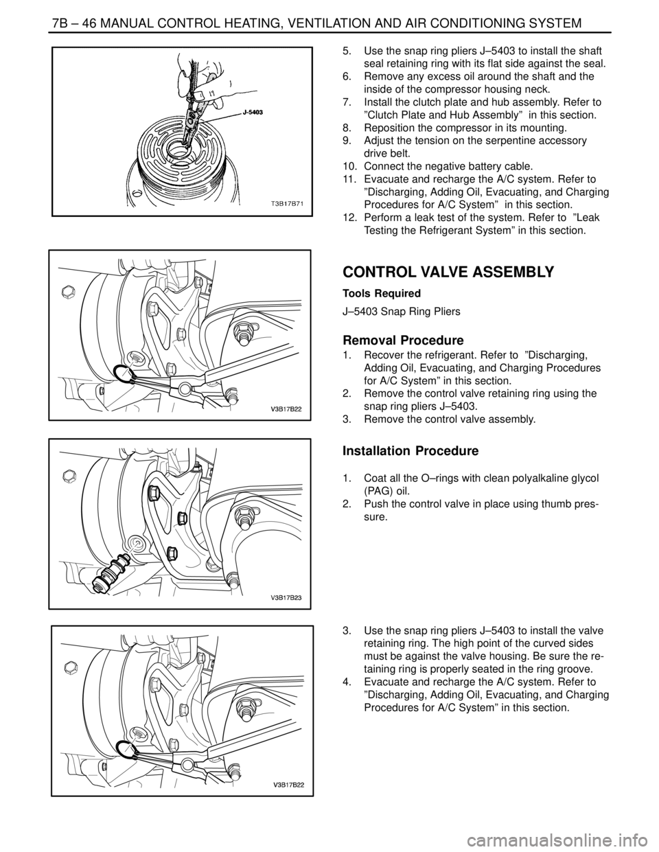
5. Use the snap ring pliers J–5403 to install the shaft
seal retaining ring with its flat side against the seal.
6. Remove any excess oil around the shaft and the
inside of the compressor housing neck.
7. Install the clutch plate and hub assembly. Refer to
”Clutch Plate and Hub Assembly” in this section.
8. Reposition the compressor in its mounting.
9. Adjust the tension on the serpentine accessory
drive belt.
10. Connect the negative battery cable.
11. Evacuate and recharge the A/C system. Refer to
”Discharging, Adding Oil, Evacuating, and Charging
Procedures for A/C System” in this section.
12. Perform a leak test of the system. Refer to ”Leak
Testing the Refrigerant System” in this section.
CONTROL VALVE ASSEMBLY
Tools Required
J–5403 Snap Ring Pliers
Removal Procedure
1. Recover the refrigerant. Refer to ”Discharging,
Adding Oil, Evacuating, and Charging Procedures
for A/C System” in this section.
2. Remove the control valve retaining ring using the
snap ring pliers J–5403.
3. Remove the control valve assembly.
Installation Procedure
1. Coat all the O–rings with clean polyalkaline glycol
(PAG) oil.
2. Push the control valve in place using thumb pres-
sure.
3. Use the snap ring pliers J–5403 to install the valve
retaining ring. The high point of the curved sides
must be against the valve housing. Be sure the re-
taining ring is properly seated in the ring groove.
4. Evacuate and recharge the A/C system. Refer to
”Discharging, Adding Oil, Evacuating, and Charging
Procedures for A/C System” in this section.
Page 2049 of 2643
MANUAL CONTROL HEATING, VENTILATION AND AIR CONDITIONING SYSTEM 7B – 47
DAEWOO V–121 BL4
REAR HEAD, GASKET, VALVE
PLATE, REED PLATE, AND O–RING
Tools Required
J–34993 Cylinder Alignment Rods
Removal Procedure
1. Recover the refrigerant. Refer to ”Discharging, Add-
ing Oil, Evacuating, and Charging Procedures for
A/C System” in this section.
2. Discharge the A/C system. Refer to ”Discharging,
Adding Oil, Evacuating, and Charging Procedures
for A/C System” in this section.
3. Remove the compressor. Refer to ”Compressor” in
this section.
4. Drain the oil from compressor into a suitable con-
tainer. Measure and record the amount of oil
drained from the compressor. Discard the used oil.
5. Remove the clutch plate and hub assembly. Refer
to ”Clutch Plate and Hub Assembly” in this section.
6. Remove the clutch rotor and bearing. Refer to
”Clutch Rotor and Bearing” in this section.
7. Remove the clutch coil. Refer to ”Clutch Coil” in
this section.
8. Remove the compressor through–bolts. Remove
and discard the gaskets.
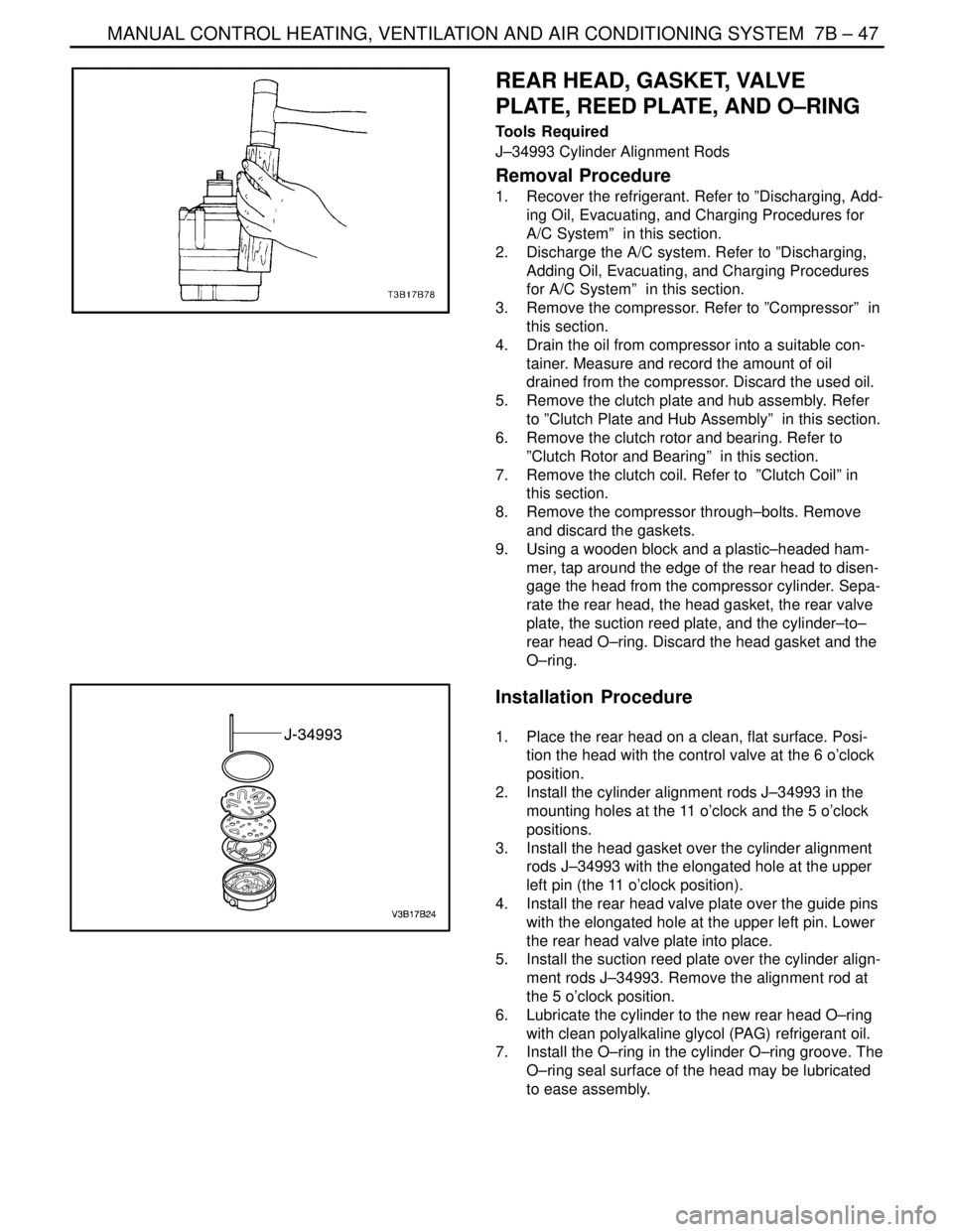
9. Using a wooden block and a plastic–headed ham-
mer, tap around the edge of the rear head to disen-
gage the head from the compressor cylinder. Sepa-
rate the rear head, the head gasket, the rear valve
plate, the suction reed plate, and the cylinder–to–
rear head O–ring. Discard the head gasket and the
O–ring.
Installation Procedure
1. Place the rear head on a clean, flat surface. Posi-
tion the head with the control valve at the 6 o’clock
position.
2. Install the cylinder alignment rods J–34993 in the
mounting holes at the 11 o’clock and the 5 o’clock
positions.
3. Install the head gasket over the cylinder alignment
rods J–34993 with the elongated hole at the upper
left pin (the 11 o’clock position).
4. Install the rear head valve plate over the guide pins
with the elongated hole at the upper left pin. Lower
the rear head valve plate into place.
5. Install the suction reed plate over the cylinder align-
ment rods J–34993. Remove the alignment rod at
the 5 o’clock position.
6. Lubricate the cylinder to the new rear head O–ring
with clean polyalkaline glycol (PAG) refrigerant oil.
7. Install the O–ring in the cylinder O–ring groove. The
O–ring seal surface of the head may be lubricated
to ease assembly.
Page 2050 of 2643
7B – 48IMANUAL CONTROL HEATING, VENTILATION AND AIR CONDITIONING SYSTEM
DAEWOO V–121 BL4
8. With the O–ring in place on the rear of the cylinder
assembly, locate the relief boss for the compressor
guide pin at the 6 o’clock position, directly above
the hole in the side of the rear head. Carefully lower
the cylinder and the front head assembly over the
guide pin to the rear head.
9. Press the cylinder and the compressor housing as-
sembly down onto the rear head using both hands.
10. Add the new through–bolt gasket to the through–
bolts and install it into the compressor assembly.
Four of the through–bolts must thread into the rear
head before removing the alignment rod.
Tighten
Alternately tighten the through–bolts in progressive
torque sequence to 10 NSm (89 lb–in).
11. Add new PAG refrigerant oil as determined in Step
1 of Removal Procedure.
12. Place the shaft nut on the shaft and rotate the com-
pressor shaft several times.
13. Perform a leak test on the compressor. Refer to
”Leak Testing (External)” in this section.
14. Install the clutch coil. Refer to ”Clutch Coil” in this
section.
15. Install the clutch rotor and bearing. Refer to ”Clutch
Rotor and Bearing” in this section.
16. Install the clutch plate and hub assembly. Refer to
”Clutch Plate and Hub Assembly” in this section.
17. Install the compressor. Refer to ”Compressor” in
this section.
18. Evacuate and recharge the A/C system. Refer to
”Discharging, Adding Oil, Evacuating, and Charging
Procedures for A/C System” in this section.
CYLINDER–TO–FRONT HEAD
O–RING
Tools Required
J–34993 Cylinder Alignment Rods
J–35372 Support Block
Removal Procedure
1. Recover the refrigerant. Refer to ”Discharging, Add-
ing Oil, Evacuating, and Charging Procedures for
A/C System” in this section.
2. Remove the compressor. Refer to ”Compressor” in
this section.
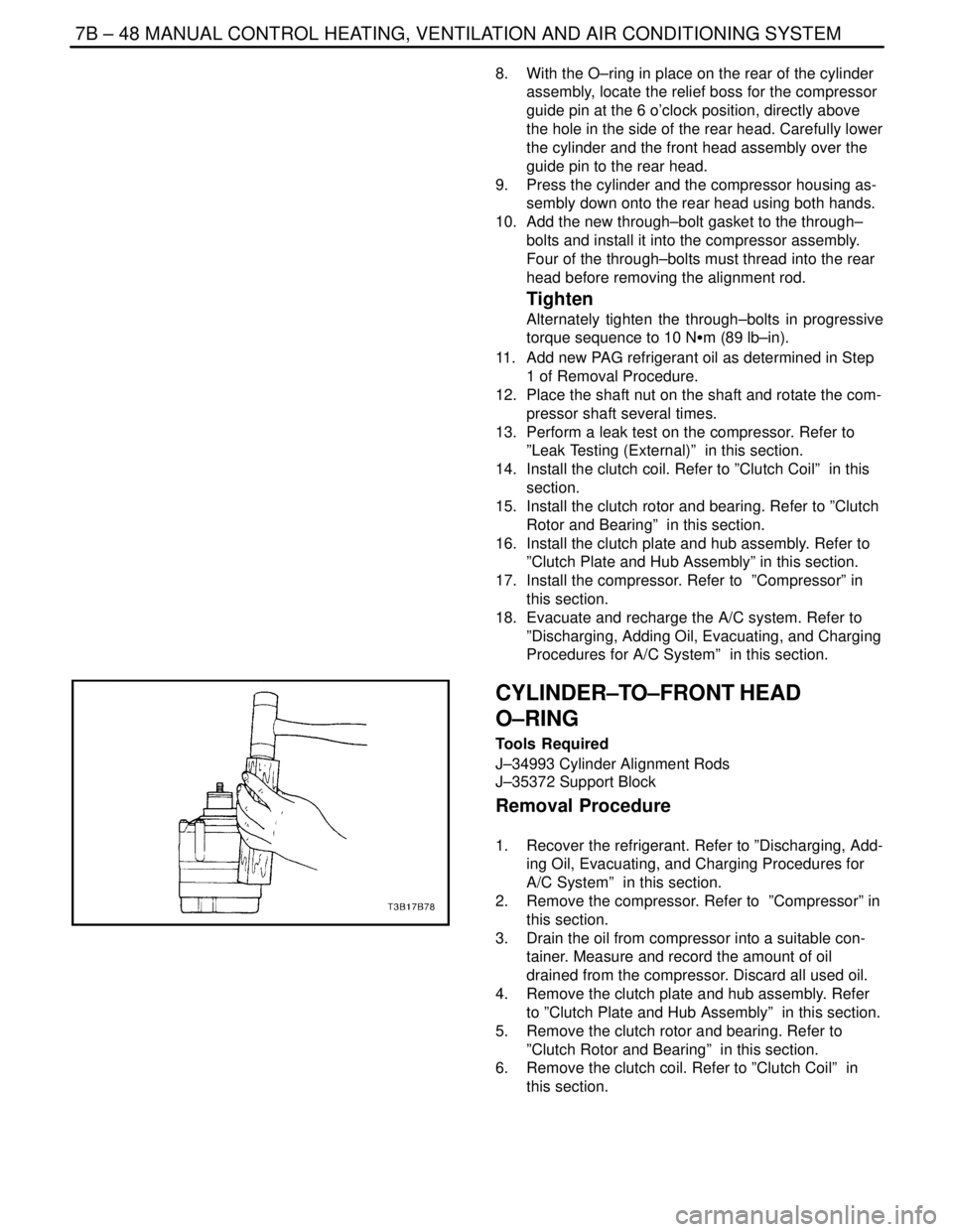
3. Drain the oil from compressor into a suitable con-
tainer. Measure and record the amount of oil
drained from the compressor. Discard all used oil.
4. Remove the clutch plate and hub assembly. Refer
to ”Clutch Plate and Hub Assembly” in this section.
5. Remove the clutch rotor and bearing. Refer to
”Clutch Rotor and Bearing” in this section.
6. Remove the clutch coil. Refer to ”Clutch Coil” in
this section.
Page 2051 of 2643
MANUAL CONTROL HEATING, VENTILATION AND AIR CONDITIONING SYSTEM 7B – 49
DAEWOO V–121 BL4
7. Remove and discard the shaft seal parts. Refer to
”Shaft Seal Replacement” in this section.
8. Remove the compressor through–bolts. Remove
and discard the gaskets.
9. Using a wooden block and a plastic–headed ham-
mer, tap the compressor housing at the mounting
locations to disengage the housing from the com-
pressor cylinder.
Important : Note the assembly sequence of the thrust
washer and bearing for ease of assembly.
10. Remove the thrust washer and the bearing.
11. Remove and discard the compressor housing–to–
cylinder O–ring.
Installation Procedure
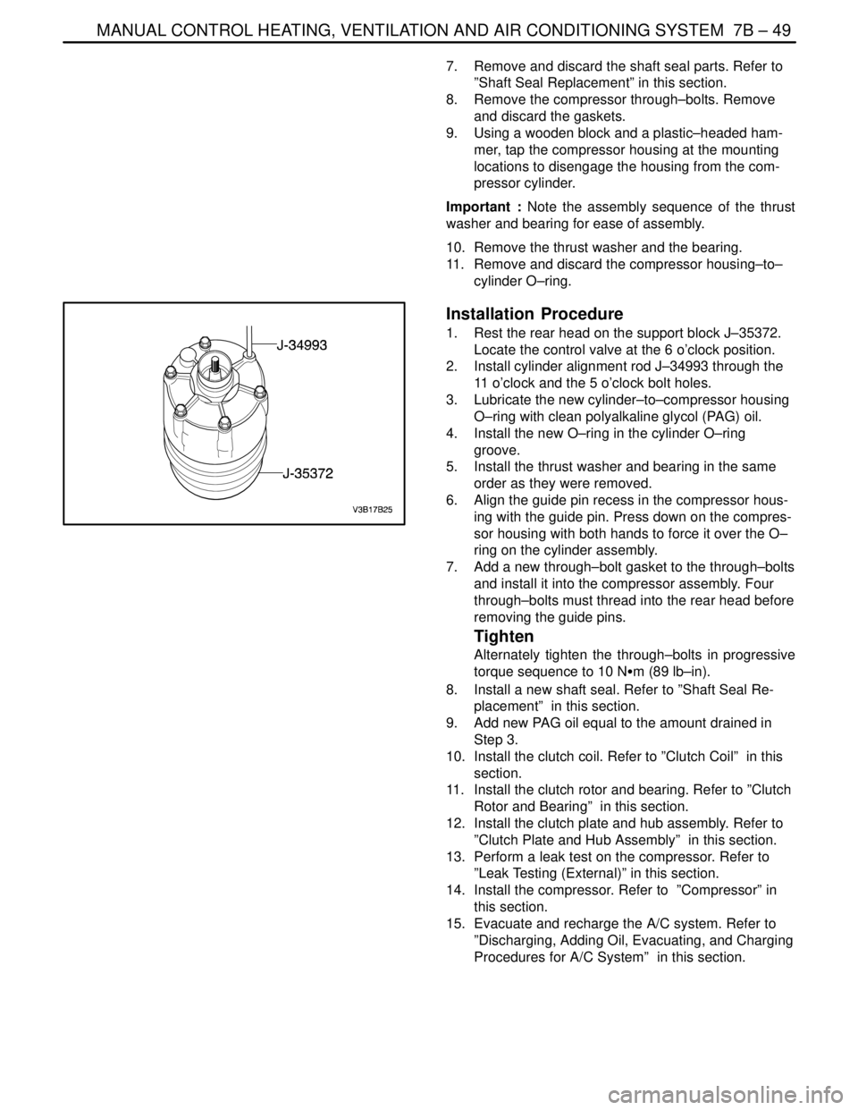
1. Rest the rear head on the support block J–35372.
Locate the control valve at the 6 o’clock position.
2. Install cylinder alignment rod J–34993 through the
11 o’clock and the 5 o’clock bolt holes.
3. Lubricate the new cylinder–to–compressor housing
O–ring with clean polyalkaline glycol (PAG) oil.
4. Install the new O–ring in the cylinder O–ring
groove.
5. Install the thrust washer and bearing in the same
order as they were removed.
6. Align the guide pin recess in the compressor hous-
ing with the guide pin. Press down on the compres-
sor housing with both hands to force it over the O–
ring on the cylinder assembly.
7. Add a new through–bolt gasket to the through–bolts
and install it into the compressor assembly. Four
through–bolts must thread into the rear head before
removing the guide pins.
Tighten
Alternately tighten the through–bolts in progressive
torque sequence to 10 NSm (89 lb–in).
8. Install a new shaft seal. Refer to ”Shaft Seal Re-
placement” in this section.
9. Add new PAG oil equal to the amount drained in
Step 3.
10. Install the clutch coil. Refer to ”Clutch Coil” in this
section.
11. Install the clutch rotor and bearing. Refer to ”Clutch
Rotor and Bearing” in this section.
12. Install the clutch plate and hub assembly. Refer to
”Clutch Plate and Hub Assembly” in this section.
13. Perform a leak test on the compressor. Refer to
”Leak Testing (External)” in this section.
14. Install the compressor. Refer to ”Compressor” in
this section.
15. Evacuate and recharge the A/C system. Refer to
”Discharging, Adding Oil, Evacuating, and Charging
Procedures for A/C System” in this section.