2004 DAEWOO LACETTI Points
[x] Cancel search: PointsPage 2194 of 2643
8B – 90ISUPPLEMENTAL INFLATABLE RESTRAINTS (SIR)
DAEWOO V–121 BL4
ACCIDENT WITH DEPLOYMENT
COMPONENTS REPLACEMENTS
All SIR components must be replaced after frontal
crash involving airbag deployment. After deployment,
a powdery residue may be on the surface of the air-
bag. The powder consists primarily of corn-
starch(used to lubricate the bag as it inflates) and by–
products of the chemical reaction. The sodium
hydroxide then quickly reacts with atmospheric mois-
ture and is converted to sodium bicarbonate(also
known as baking soda). Therefore, it is unlikely that
sodium hydroxide will be present after deployment.
Replace the following SIR components.
CAUTION : Wear gloves and safely glasses dur-
ing the disposal procedure. Refer to ”Deployed
airbag module disposal procedure” in this sec-
tion.
S The SDM
S Airbag modules and pretensioners
S SIR wiring
S Clock spring
ACCIDENT WITHOUT DEPLOYMENT
COMPONENT INSPECTION
Certain inspection must be performed after any
crash, whether the airbag has deployed or not. :
S The steering column must be dimensionally in-
spected.
S Inspect the knee bolsters and mounting points for
distortion, bending and cracking or other damages.
S Inspect the instrument panel(I/P) and steering col-
umn reinforcement plate for distorsion, bending and
cracking or other damage.
S Inspect the I/P braces for distortion, bending and
cracking or other damage.
S Inspect the seat belt and mounting points. Refer to
Section 8A, Seat Belts.
SENSING AND DIAGNOSTIC
MODULE (SDM)
CAUTION : During service procedure, be very
careful when handling the SDM. Never strike or
jar the SDM. Never power the supplemental inflat-
able restraints(SIR) when the SDM is not rigidly
attached to the vehicle. All SDM mounting bolts
must be carefully tightened , and the arrow on the
SDM must be point toward the front of the vehicle
to ensure proper operation of the SIR. The SDM
could be activated if it is powered when it is not
rigidly attached to the vehicle, resulting in unex-
pected deployment and possible injury.
Page 2506 of 2643
NUBIRA/LACETTISERVICE NOTICE 0–3
1. HOW TO USE THIS MANUAL
.
This manual covers the repairs of NUBIRA/LACETTI
automobile which has been involved in accidents, and it
describes the work related to the replacement of dam-
aged body parts.
Please read through these instructions and familiarize
yourself with them before actually using this manual.
.
Note : Refer to NUBIRA/LACETTI Service Manual for
specifications, wire harness locations, safety stand sup-
port points, etc.
2. SPECIAL INFORMATION
.
Indicates a strong possibility of personal injury or equip-
ment damage if instructions are not followed.
.
Note : Gives helpful information.
.
CAUTION : Detailed descriptions of standard work-
shop procedures, safety principles and service op-
erations are not included. Please note that this manu-
al does contain warnings and cautions against some
specific service methods which could cause PER-
SONAL INJURY, or could damage a vehicle or make
it unsafe. Please understand that these warnings can-
not cover all conceivable ways in which service,
whether or not recommended by GM DAEWOO might
be done or of the possible hazardous consequences
of each conceivable way, not could GM DAEWOO in-
vestigate all such ways. Anyone using service proce-
dures or tools, whether or not recommended by GM
DAEWOO, must satisfy himself thoroughly that nei-
ther personal safety or tools, whether or not recom-
mended by GM DAEWOO, must satisfy himself thor-
oughly that neither personal safety or vehicle safety
will be jeopardized.
.
All information contained in this manual is based on the
latest product information available at the time of print-
ing. We reserve the right to make changes at any time
without notice. No part of this publication may be repro-
duced, stored in retrieval system, or transmitted, in any
form by any means, electronic, mechanical, photocopy-
ing, recording, or otherwise, without the prior written
permission of the publisher. This includes text, figures
and tables.
Page 2521 of 2643

NUBIRA/LACETTI PREPARATIONS OF BODYWORK 2–1
SECTION 2
PREPARATIONS OF BODYWORK
CONTENTS
1. GENERAL DESCRIPTION 2 – 2. . . . . . . . . . . . . . . . . . . . . . . . . . . . . . . . . . . . . . . . . . .
2. CHECKPOINTS 2 – 4. . . . . . . . . . . . . . . . . . . . . . . . . . . . . . . . . . . . . . . . . . . . . . . . . . . .
3. CORRECTION OF THE DAMAGED AREA 2 – 5. . . . . . . . . . . . . . . . . . . . . . . . . . . .
4. MEASURING SYSTEMS (WITHOUT SMALL DAMAGE) 2 – 6. . . . . . . . . . . . . . . .
Page 2524 of 2643
2–4 PREPARATIONS OF BODYWORK NUBIRA/LACETTI
2. CHECKPOINTS
S Accurate Inspection of Damaged Parts(Visual)
.
Seat Belts
Always replace the seat belt if :
1. The belt material is cut, punctured, burned or in any
way damaged.
2. The buckle or retractor does not work properly.
3. They were being worn at the time of a collision(also
check for damage at the seat belt anchor points).
4. Their condition is questionable.
.
Front Section :
1. Is there any bending, splitting, denting or other dam-
age to the suspension and its related parts?
2. Is there any deformation of the front panel or radiator
crossmember? Have any of the connected sections
come apart?
3. Are there any creases or distortion in the front wheel-
house or side frame? Have any of the connected sec-
tions come apart?
4. Is there any bending or twisting of the whole front
area?
5. Is there any deformation like creases, bulges, or dents
in the front pillar, dash panel, floor, etc.?
6. Is there any vertical twisting or misaligned clearance
in the door?
7. Is the windshield seal broken?
8. Is there any deformation in the vicinity of the top part
of the roof panel’s center pillar?
9. Is there any damage inside the automobile(is there
any twisting of the dash panel, or anything irregular with
the clearances or sheet–mounting parts)?
10. Is there any damage to the steering wheel? Is there
any deformation in the column and the column–mounted
parts?
11. Is there any oil or water leakage and damage to the en-
gine, transmission or brakes?
12. Is there any irregular noise in the gear changing opera-
tion, engine and transmission rotation?
13. Are there any traces of contact between the engine
block and the center crossmember ?
14. Is there any damage to brake or fuel lines, or wire har-
nesses?Rear Section :
1. Is there any twisting, bulging or denting of the rear floor
any rear bolsters? Have any of the connected sections
come apart?
2. Is there any irregular bulging or denting in the rear
fender?
3. Is there any distortion in the rear inner panel? Is there
any bending and denting in the vicinity of the rear pillar?
4. Is there any distortion or creasing is the rear wheel-
house and arch sections? Have any of the connected
sections come apart?
5. Is there anything irregular in the rear glass seal clear-
ance?
6. Is there any twisting or misalignment of the clearance
of the trunk lid opening section?
7. Is there any bending, splitting, denting or other dam-
age to the suspension and its related parts?
8. Is there any deformation of the rear floor crossmem-
ber, trunk floor panel and back panel? Have any of the
connected sections come apart?
.
Impact Beam :
Always replace the door assembly if :
1. The external force makes the impact beam of door in-
ner deform.
Always replace impact beam if :
2. The external force makes the impact beam of front
bumper and rear bumper deform.
Page 2528 of 2643
3–2 WELDING AND TOOLSNUBIRA/LACETTI
1. SPOT WELDING
1–1. GENERAL DESCRIPTION
.
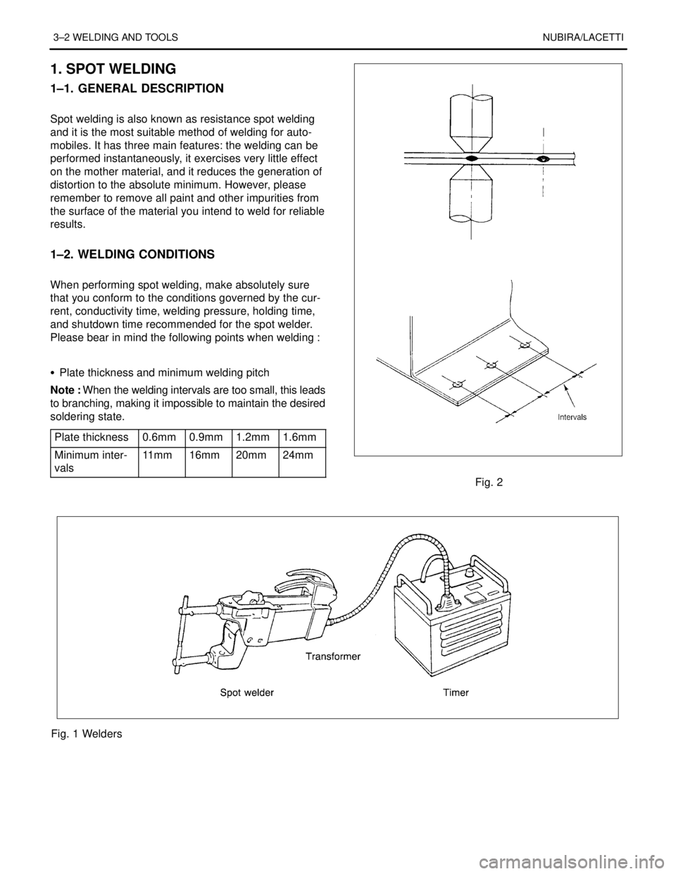
Spot welding is also known as resistance spot welding
and it is the most suitable method of welding for auto-
mobiles. It has three main features: the welding can be
performed instantaneously, it exercises very little effect
on the mother material, and it reduces the generation of
distortion to the absolute minimum. However, please
remember to remove all paint and other impurities from
the surface of the material you intend to weld for reliable
results.
.
1–2. WELDING CONDITIONS
.
When performing spot welding, make absolutely sure
that you conform to the conditions governed by the cur-
rent, conductivity time, welding pressure, holding time,
and shutdown time recommended for the spot welder.
Please bear in mind the following points when welding :
.
S Plate thickness and minimum welding pitch
Note : When the welding intervals are too small, this leads
to branching, making it impossible to maintain the desired
soldering state.
Plate thickness
0.6mm0.9mm1.2mm1.6mm
Minimum inter-
vals11 m m16mm20mm24mm
Fig. 2
Fig. 1 Welders
Page 2537 of 2643
NUBIRA/LACETTIFRONT 4–3
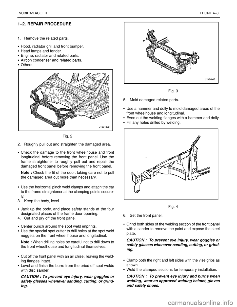
1–2. REPAIR PROCEDURE
1. Remove the related parts.
S Hood, radiator grill and front bumper.
S Head lamps and fender.
S Engine, radiator and related parts.
S Aircon condenser and related parts.
S Others.
Fig. 2
2. Roughly pull out and straighten the damaged area.
S Check the damage to the front wheelhouse and front
longitudinal before removing the front panel. Use the
frame straightener to roughly pull out and repair the
damaged front panel before removing the front panel.
Note : Check the fit of the door, taking care not to pull
the damaged area out more than necessary.
S Use the horizontal pinch weld clamps and attach the car
to the frame straightener at the clamping points secure-
ly.
3. Keep the body, level.
S Jack up the body, and place safety stands at the four
designated places of the frame door opening.
4. Cut and pry off the front panel.
S Center punch around the spot weld imprints.
S Use the special spot cutter to drill holes at the spot weld
nuggets on the front wheel house and longitudinal.
Note : When drilling holes be careful not to drill down to
the front wheelhouse and longitudinal themselves.
S Cut off the front panel with an air chisel, leaving the weld-
ing flanges intact.
S Level and finish the burrs from the pried off spot welds
with disc sander.
CAUTION : To prevent eye injury, wear goggles or
safety glasses whenever sanding, cutting, or grind-
ing.
Fig. 3
5. Mold damaged related parts.
S Use a hammer and dolly to mold damaged areas of the
front wheelhouse and longitudinal.
S Even out the welding flanges with a hammer and dolly.
S Fill any holes drilled by welding.
Fig. 4
6. Set the front panel.
S Grind both sides of the welding section of the front panel
with a sander to remove the paint and expose the steel
plate.
CAUTION : To prevent eye injury, wear goggles or
safety glasses whenever sanding, cutting, or grind-
ing.
S Clamp both the right and left sides with the vise grips as
shown.
S Weld the clamped sections for temporary installation.
CAUTION : To prevent eye injury and burns when
welding, wear an approved welding helmet, gloves
and safety shoes.
Page 2541 of 2643
NUBIRA/LACETTIFRONT 4–7
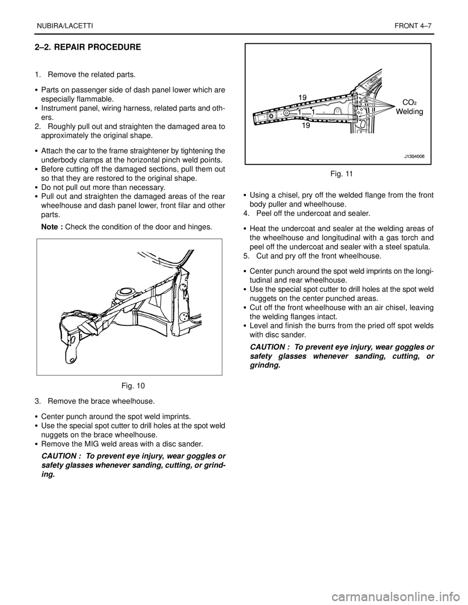
2–2. REPAIR PROCEDURE
1. Remove the related parts.
S Parts on passenger side of dash panel lower which are
especially flammable.
S Instrument panel, wiring harness, related parts and oth-
ers.
2. Roughly pull out and straighten the damaged area to
approximately the original shape.
S Attach the car to the frame straightener by tightening the
underbody clamps at the horizontal pinch weld points.
S Before cutting off the damaged sections, pull them out
so that they are restored to the original shape.
S Do not pull out more than necessary.
S Pull out and straighten the damaged areas of the rear
wheelhouse and dash panel lower, front filar and other
parts.
Note : Check the condition of the door and hinges.
Fig. 10
3. Remove the brace wheelhouse.
S Center punch around the spot weld imprints.
S Use the special spot cutter to drill holes at the spot weld
nuggets on the brace wheelhouse.
S Remove the MIG weld areas with a disc sander.
CAUTION : To prevent eye injury, wear goggles or
safety glasses whenever sanding, cutting, or grind-
ing.
Fig. 11
S Using a chisel, pry off the welded flange from the front
body puller and wheelhouse.
4. Peel off the undercoat and sealer.
S Heat the undercoat and sealer at the welding areas of
the wheelhouse and longitudinal with a gas torch and
peel off the undercoat and sealer with a steel spatula.
5. Cut and pry off the front wheelhouse.
S Center punch around the spot weld imprints on the longi-
tudinal and rear wheelhouse.
S Use the special spot cutter to drill holes at the spot weld
nuggets on the center punched areas.
S Cut off the front wheelhouse with an air chisel, leaving
the welding flanges intact.
S Level and finish the burrs from the pried off spot welds
with disc sander.
CAUTION : To prevent eye injury, wear goggles or
safety glasses whenever sanding, cutting, or
grindng.
Page 2545 of 2643
NUBIRA/LACETTIFRONT 4–11
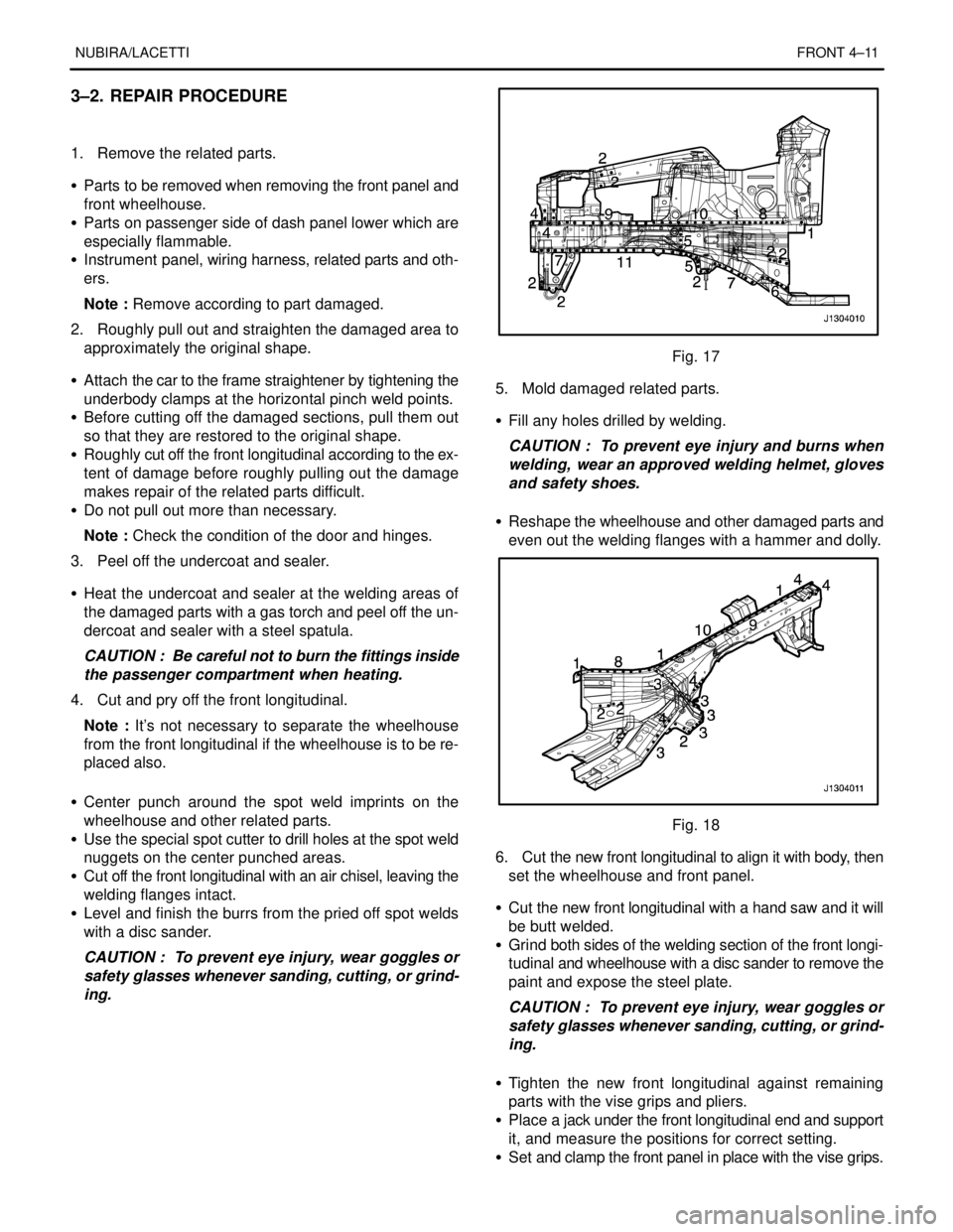
3–2. REPAIR PROCEDURE
1. Remove the related parts.
S Parts to be removed when removing the front panel and
front wheelhouse.
S Parts on passenger side of dash panel lower which are
especially flammable.
S Instrument panel, wiring harness, related parts and oth-
ers.
Note : Remove according to part damaged.
2. Roughly pull out and straighten the damaged area to
approximately the original shape.
S Attach the car to the frame straightener by tightening the
underbody clamps at the horizontal pinch weld points.
S Before cutting off the damaged sections, pull them out
so that they are restored to the original shape.
S Roughly cut off the front longitudinal according to the ex-
tent of damage before roughly pulling out the damage
makes repair of the related parts difficult.
S Do not pull out more than necessary.
Note : Check the condition of the door and hinges.
3. Peel off the undercoat and sealer.
S Heat the undercoat and sealer at the welding areas of
the damaged parts with a gas torch and peel off the un-
dercoat and sealer with a steel spatula.
CAUTION : Be careful not to burn the fittings inside
the passenger compartment when heating.
4. Cut and pry off the front longitudinal.
Note : It’s not necessary to separate the wheelhouse
from the front longitudinal if the wheelhouse is to be re-
placed also.
S Center punch around the spot weld imprints on the
wheelhouse and other related parts.
S Use the special spot cutter to drill holes at the spot weld
nuggets on the center punched areas.
S Cut off the front longitudinal with an air chisel, leaving the
welding flanges intact.
S Level and finish the burrs from the pried off spot welds
with a disc sander.
CAUTION : To prevent eye injury, wear goggles or
safety glasses whenever sanding, cutting, or grind-
ing.
Fig. 17
5. Mold damaged related parts.
S Fill any holes drilled by welding.
CAUTION : To prevent eye injury and burns when
welding, wear an approved welding helmet, gloves
and safety shoes.
S Reshape the wheelhouse and other damaged parts and
even out the welding flanges with a hammer and dolly.
Fig. 18
6. Cut the new front longitudinal to align it with body, then
set the wheelhouse and front panel.
S Cut the new front longitudinal with a hand saw and it will
be butt welded.
S Grind both sides of the welding section of the front longi-
tudinal and wheelhouse with a disc sander to remove the
paint and expose the steel plate.
CAUTION : To prevent eye injury, wear goggles or
safety glasses whenever sanding, cutting, or grind-
ing.
S Tighten the new front longitudinal against remaining
parts with the vise grips and pliers.
S Place a jack under the front longitudinal end and support
it, and measure the positions for correct setting.
S Set and clamp the front panel in place with the vise grips.