2004 DAEWOO LACETTI Points
[x] Cancel search: PointsPage 1405 of 2643

5A1 – 56IZF 4 HP 16 AUTOMATIC TRANSAXLE
DAEWOO V–121 BL4
SYMPTOM DIAGNOSIS
Oil Leakage
Notice :
– Careful localization of leakage points may make it
possible to prevent incorrect or cost–intensive re-
pairs.
Test Steps :– Thoroughly clean the transaxle, engine, and sur-
rounding area(using a steam jet, for example).
– To locate leakage, use a suitable identifying spray
or similar product.
– Depending on the amount of leakage, take the
car for a short or a longer test drive – It may prove
sufficient to place the car on a hoist and run the
engine at idle speed to trace the leak.
– If possible, determine exactly which type of oil is
escaping.
Symptom
Possible CauseAction
Transaxle Oil Leak-
ageOil Pump(Torque Converter Sealing)S Visually check torque converter sealing.
S Replace the converter sealing as described in
the transaxle repair on the vehicle service.
Crankshaft Sealing RingS Check whether engine oil or TFT is leaking out.
S If leak is engine oil, replace the sealing ring as
described in the engine repair instruction.
Torque ConverterS Visual check.
S Fit an exchange converter as described in the
repair instruction.
Oil Content Too HighS Check oil level(TFT and axle oil) as described
in this chapter.
S Correct oil level, and recheck after a test drive.
Notice : Comply with the measuring procedure (fill-
ing procedure) in the repair instruction. Check the oil
level at the overflow plug adjust to proper level if nec-
essary.
O–ring at Bolt Head Damaged or Miss-
ingS Check O–ring.
S Replace O–ring as described in the repair in-
struction.
Shaft SealS Visually check the shaft seal.
S Replace the sealing ring as described in the
repair instruction.
Hose Clamp LooseS Check to ensure that the hose clamp fits tightly.
S If necessary, retighten clamp.
Oil Pan Gasket Not Installed ProperlyS Check to see if the gasket was positioned
properly.
S Install gasket properly as described in the re-
pair instruction.
Oil Pan Gasket DamagedS Check the gasket visually.
S Replace gasket as described in the repair in-
struction.
Bolt at Bracket LooseCheck the Tightening Torque
Retighten bolt
Sealing Ring at Oil DipstickS Check O–ring.
S If necessary, replace O–ring.
Sealing Ring Near End–Cover Connec-
tion DefectiveS Check sealing rings.
S Put in new sealing ring Check O–ring as de-
scribed in the repair instruction.
Page 1575 of 2643

5A1 – 226IZF 4 HP 16 AUTOMATIC TRANSAXLE
DAEWOO V–121 BL4
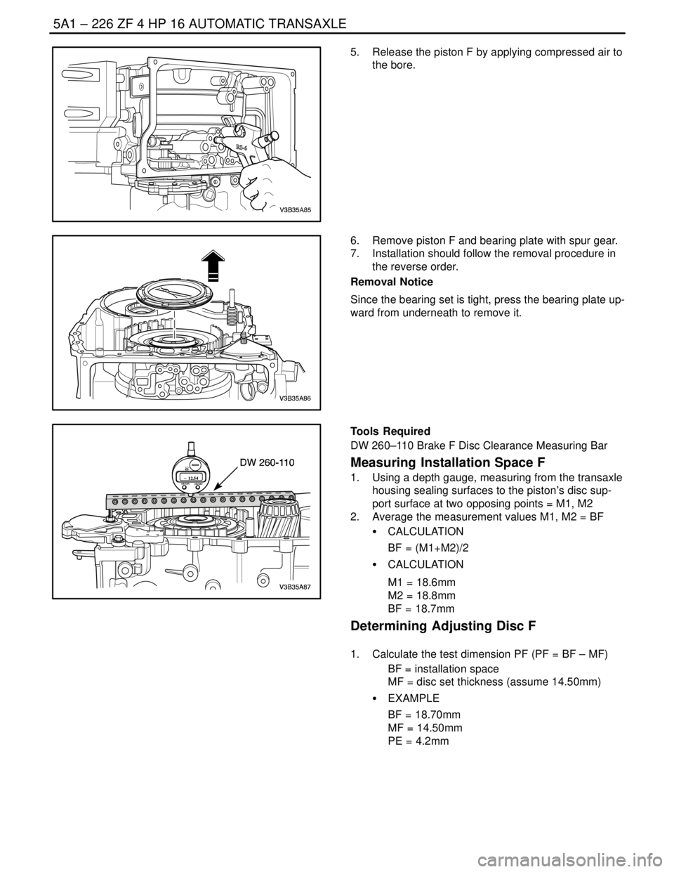
5. Release the piston F by applying compressed air to
the bore.
6. Remove piston F and bearing plate with spur gear.
7. Installation should follow the removal procedure in
the reverse order.
Removal Notice
Since the bearing set is tight, press the bearing plate up-
ward from underneath to remove it.
ORIGIN
ON/OFF– 12.54
+ / –
ORIGIN
ON/OFF– 12.54
+ / –
Tools Required
DW 260–110 Brake F Disc Clearance Measuring Bar
Measuring Installation Space F
1. Using a depth gauge, measuring from the transaxle
housing sealing surfaces to the piston’s disc sup-
port surface at two opposing points = M1, M2
2. Average the measurement values M1, M2 = BF
S CALCULATION
BF = (M1+M2)/2
S CALCULATION
M1 = 18.6mm
M2 = 18.8mm
BF = 18.7mm
Determining Adjusting Disc F
1. Calculate the test dimension PF (PF = BF – MF)
BF = installation space
MF = disc set thickness (assume 14.50mm)
S EXAMPLE
BF = 18.70mm
MF = 14.50mm
PE = 4.2mm
Page 1588 of 2643

ZF 4 HP 16 AUTOMATIC TRANSAXLE 5A1 – 239
DAEWOO V–121 BL4
S Excessive transaxle fluid leaking into the connector,
wicking up into the external wiring harness, and
degrading the wire insulation.
S Water/moisture intrusion in the connector.
S Low pin retention in the external connector from
excessive connection and disconnection of the wir-
ing connector assembly.
S Pin corrosion from contamination.
S Broken/cracked connector assembly.
S Points to remember when working with transaxle
wiring connector assembly.
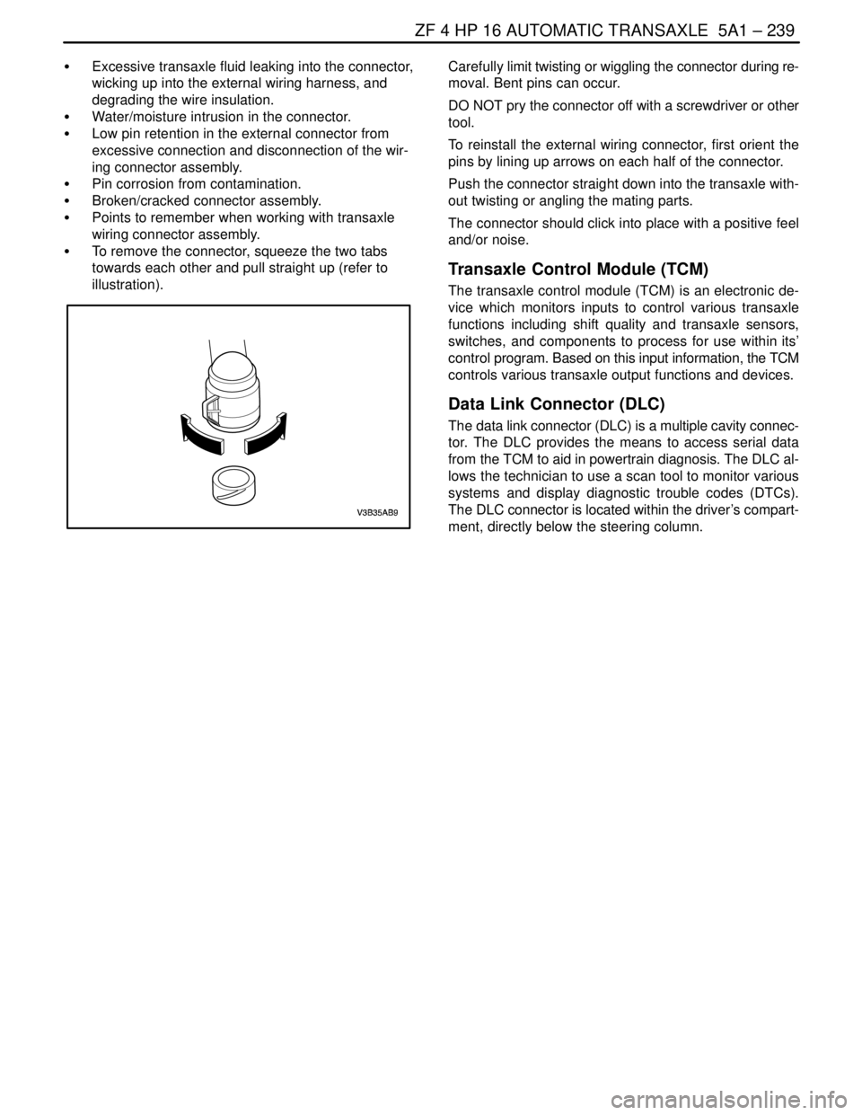
S To remove the connector, squeeze the two tabs
towards each other and pull straight up (refer to
illustration).Carefully limit twisting or wiggling the connector during re-
moval. Bent pins can occur.
DO NOT pry the connector off with a screwdriver or other
tool.
To reinstall the external wiring connector, first orient the
pins by lining up arrows on each half of the connector.
Push the connector straight down into the transaxle with-
out twisting or angling the mating parts.
The connector should click into place with a positive feel
and/or noise.
Transaxle Control Module (TCM)
The transaxle control module (TCM) is an electronic de-
vice which monitors inputs to control various transaxle
functions including shift quality and transaxle sensors,
switches, and components to process for use within its’
control program. Based on this input information, the TCM
controls various transaxle output functions and devices.
Data Link Connector (DLC)
The data link connector (DLC) is a multiple cavity connec-
tor. The DLC provides the means to access serial data
from the TCM to aid in powertrain diagnosis. The DLC al-
lows the technician to use a scan tool to monitor various
systems and display diagnostic trouble codes (DTCs).
The DLC connector is located within the driver’s compart-
ment, directly below the steering column.
Page 1808 of 2643

5A2 – 218IAISIN AUTOMATIC TRANSAXLE
DAEWOO V–121 BL4
GENERAL DESCRIPTION
AND SYSTEM OPERATION
TRANSAXLE DESCRIPTION
The new automatic transmission is an electronically con-
trolled 4–speed automatic transmission with Lock–up
mechanism.
The transmission is mainly composed of the torque con-
verter with lock up clutch, newly developed 4–speed plan-
etary gear unit, the hydraulic control system and the elec-
tric control system.
ELECTRONICAL COMPONENTS
Transmission Control Module (TCM)
The TCM primarily controls shift points and lockup en-
gagement. It is located on the driver side under the instru-
ment panel.
The transmission is controlled by an electronic shift sys-
tem. The Transmission Control Module (TCM) processes
input signals. From the information received, the TCM
controls the transmission hydraulic system.
The electronic shift system consists of the following :
S Transmission control module (TCM)
S Shift solenoids (SS1 and SS2)
S Pressure control solenoid (PCS)
S Lockup solenoid
S Input shaft speed (ISS) sensor
S Output shaft speed (OSS) sensor
S Transmission Fluid Temperature (TFT) sensor
S Transmission Range (TR) Switch
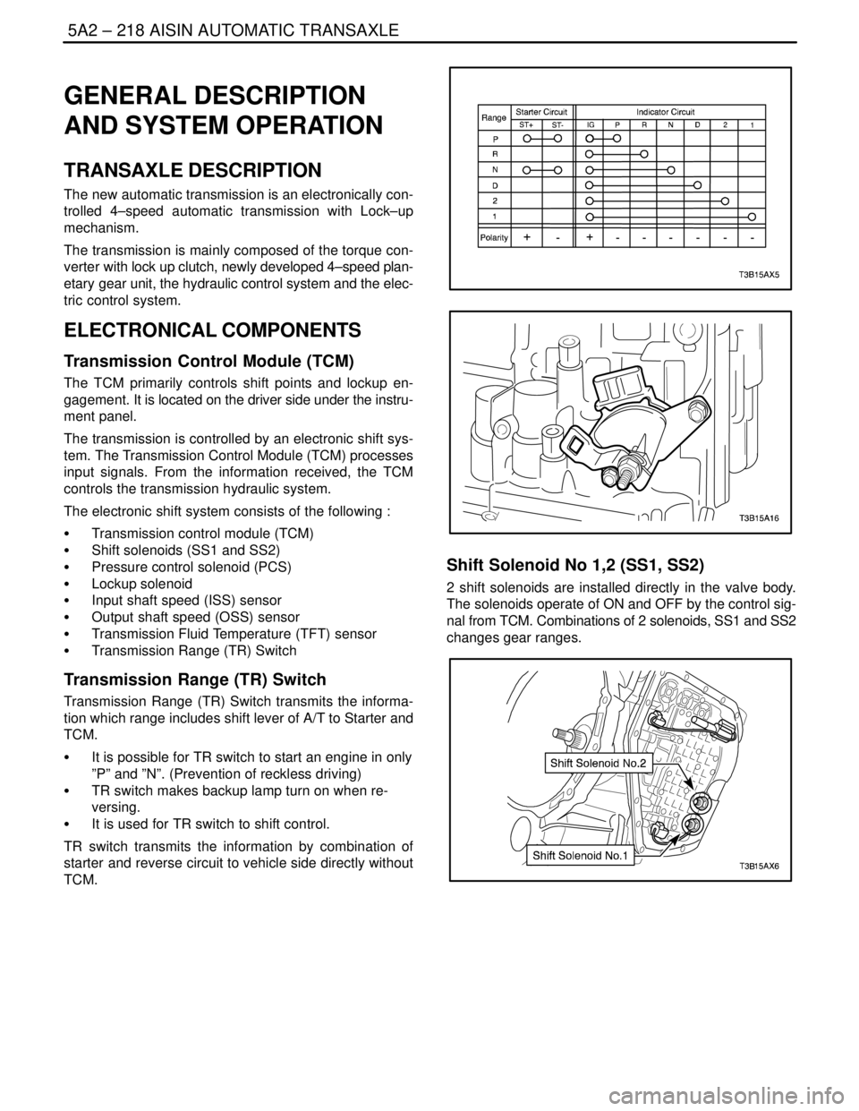
Transmission Range (TR) Switch
Transmission Range (TR) Switch transmits the informa-
tion which range includes shift lever of A/T to Starter and
TCM.
S It is possible for TR switch to start an engine in only
”P” and ”N”. (Prevention of reckless driving)
S TR switch makes backup lamp turn on when re-
versing.
S It is used for TR switch to shift control.
TR switch transmits the information by combination of
starter and reverse circuit to vehicle side directly without
TCM.
Shift Solenoid No 1,2 (SS1, SS2)
2 shift solenoids are installed directly in the valve body.
The solenoids operate of ON and OFF by the control sig-
nal from TCM. Combinations of 2 solenoids, SS1 and SS2
changes gear ranges.
Page 1809 of 2643

AISIN AUTOMATIC TRANSAXLE 5A2 – 219
DAEWOO V–121 BL4
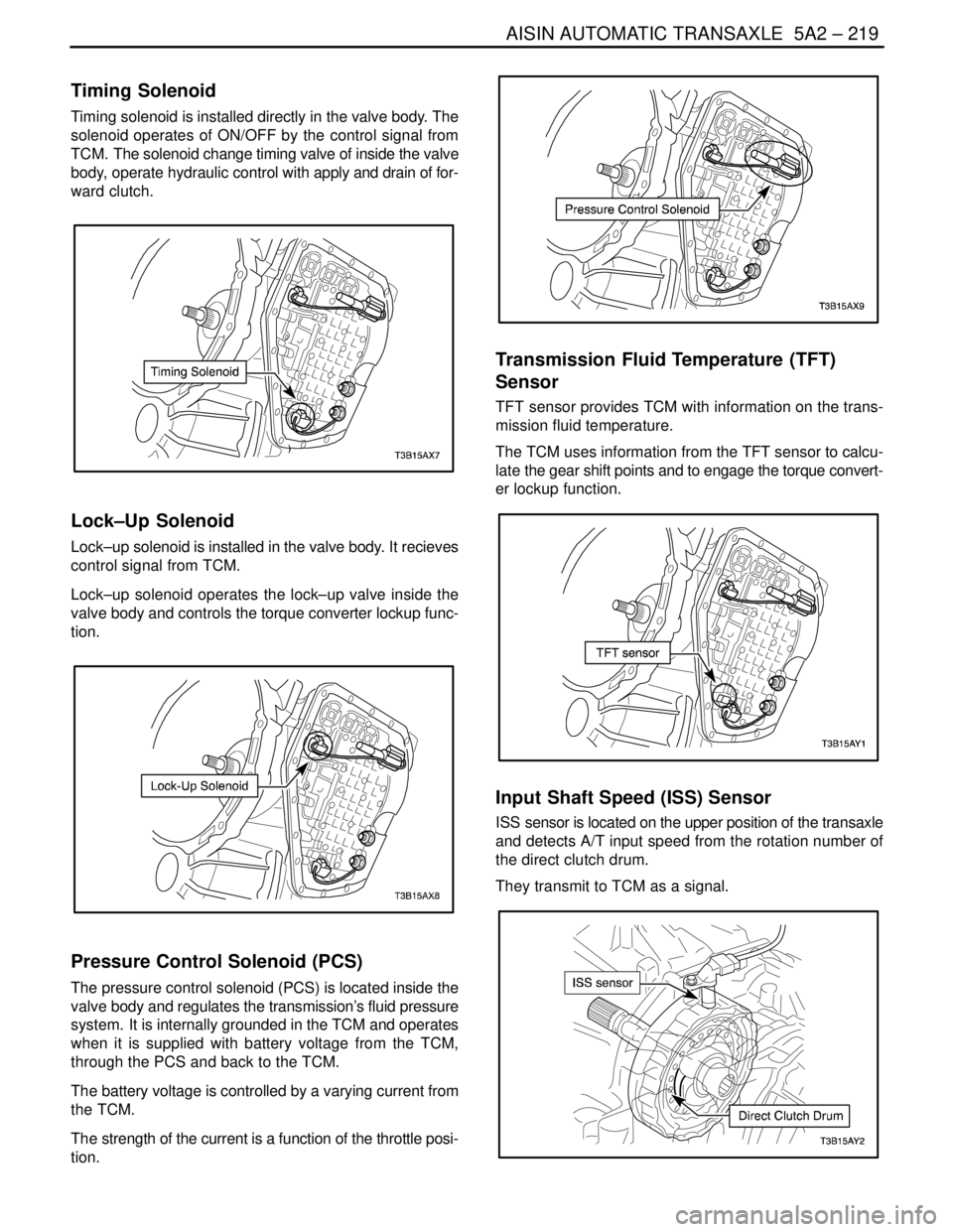
Timing Solenoid
Timing solenoid is installed directly in the valve body. The
solenoid operates of ON/OFF by the control signal from
TCM. The solenoid change timing valve of inside the valve
body, operate hydraulic control with apply and drain of for-
ward clutch.
Lock–Up Solenoid
Lock–up solenoid is installed in the valve body. It recieves
control signal from TCM.
Lock–up solenoid operates the lock–up valve inside the
valve body and controls the torque converter lockup func-
tion.
Pressure Control Solenoid (PCS)
The pressure control solenoid (PCS) is located inside the
valve body and regulates the transmission’s fluid pressure
system. It is internally grounded in the TCM and operates
when it is supplied with battery voltage from the TCM,
through the PCS and back to the TCM.
The battery voltage is controlled by a varying current from
the TCM.
The strength of the current is a function of the throttle posi-
tion.
Transmission Fluid Temperature (TFT)
Sensor
TFT sensor provides TCM with information on the trans-
mission fluid temperature.
The TCM uses information from the TFT sensor to calcu-
late the gear shift points and to engage the torque convert-
er lockup function.
Input Shaft Speed (ISS) Sensor
ISS sensor is located on the upper position of the transaxle
and detects A/T input speed from the rotation number of
the direct clutch drum.
They transmit to TCM as a signal.
Page 1922 of 2643

POWER STEERING GEAR 6C – 5
DAEWOO V–121 BL4
POWER RACK AND PINION
STEERING GEAR BENCH TESTING
Removal, Setup and Testing Procedure
Notice : Pressure checks or pressure and flow checks
may also be conducted using this set–up.
1. Disconnect and remove the power steering gear.
Refer to ”Rack and Pinion Assembly” in this sec-
tion.
2. Place the power steering gear on a bench next to
the vehicle.
3. Disconnect the pressure line at the point where the
hose connects to the pipe. Extend this line in order
to reach the power steering gear on the bench.
4. Disconnect the return line from the the power steer-
ing fluid reservoir. Extend this line in order to reach
the power steering gear on the bench.
5. Connect the power steering pipes to the power
steering gear.6. Start the engine and allow it to idle for 10 seconds.
7. Check the power steering fluid level. Refer to Sec-
tion 6A, Power Steering System.
8. Start the engine and turn the rack and pinion stub
shaft to a full turn in each direction. Hold the shaft
against each stop for 5 seconds.
9. Inspect for possible leak points. Refer to Section
6A, Power Steering System.
Installation Procedure
1. Stop the engine.
2. Disconnect the power steering pipes from the pow-
er steering gear.
3. Remove the extensions and reconnect the pressure
and return lines.
4. Install and connect the power steering gear. Refer
to ”Rack and Pinion Assembly” in this section.
5. Start the engine and stay idle for 10 seconds.
6. Check the power steering fluid level. Refer to Sec-
tion 6A, Power Steering System.
Page 1974 of 2643

6E – 20ISTEERING WHEEL AND COLUMN
DAEWOO V–121 BL4
GENERAL DESCRIPTION
AND SYSTEM OPERATION
STEERING WHEEL AND COLUMN
CAUTION : To ensure the energy–absorbing action of
the steering column, it is important to use only the
specified screws, bolts, and nuts, tightened to the
specified torque.
In addition to the steering function, the steering column
provides safety and security.
The energy–absorbing column is designed to compress in
a front–end collision to lessen the chance of driver injury.
The ignition switch and the lock are mounted on the col-
umn, allowing the ignition and steering operations to be
locked to inhibit theft of the car.
The column levers trigger the turn signals, the headlight
beams, and the windshield washer and wipers.The tilt steering column uses telescopic function to allow
the steering wheel to tilt up and down in and out. This en-
ables the driver to adjust the steering wheel to a comfort-
able position.
Notice : Apply a thin coat of lithium grease to all friction
points when reassembling.
The column may be disassembled and reassembled easi-
ly.IGNITION KEY REMINDER
The ignition key reminder alerts the driver that the key is
still in the ignition when the driver attempts to exit the ve-
hicle.
An internal switch in the ignition lock cylinder supplies bat-
tery voltage to the reminder chime module when all of the
following conditions are true:
S The key is in the ignition switch.
S The ignition is OFF.
S The driver’s door is open.
For information on removal and installation of the reminder
chime module, refer to Section 9E, Instrumentation/Driver
Information.
Page 2193 of 2643

SUPPLEMENTAL INFLATABLE RESTRAINTS (SIR) 8B – 89
DAEWOO V–121 BL4
HANDLING, INSTALLATION AND
DIAGNOSIS
S Airbag modules should not be subjected to temper-
ature above 65 degrees Celsius(149 degrees Fahr-
enheit).
S An airbag and SDM should not be used if it has
been dropped from height of 0.9 meters(3 feet) or
greater.
S When an SDM is replaced, it must be oriented with
the arrow on the SDM pointing toward the front of
the vehicle.
S It is very important for the SDM to be installed flat
on the mounting surface, parallel to the vehicle’s
longitudinal axis.
S To avoid setting diagnostic trouble codes(DTCs), do
not apply power to the SIR unless all components
are connected or a diagnostic chart request it.
S The SIR Diagnostic System Check must be the
starting point of any SIR diagnostics. The SIR Diag-
nostic System Check will verify proper airbag indi-
cator operation and will lead you to correct chart to
diagnose any SIR malfunctions. Bypassing these
procedures may result in extended diagnostic time
incorrect parts replacement.
REPAIRS AND INSPECTIONS
REQUIRED AFTER AN ACCIDENT
CAUTION : Any repairs to the vehicle’s structure
must return it to the original production configu-
ration. Deployment requires replacement of
SDM, the inflator modules and a dimensional in-
spection of the steering column.
S If any SIR components are damaged, they must be
replaced. If SIR components mounting points are
damaged, they must be repaired or replaced.
S Never use SIR parts from another vehicle. This
does not include remanufactured parts purchased
from an authorized source.
S Do not attempt to service the SDM, the clock spring
or other airbag modules, these items must be re-
placed if they are defective.
S Verify the part number of replaced airbag modules.
Some inflator modules look identical but contain
different internal components.