2004 DAEWOO LACETTI Points
[x] Cancel search: PointsPage 21 of 2643

0B – 14IGENERAL INFORMATION
DAEWOO V–121 BL4
Engine Cooling System
Inspect the coolant and freeze protection fluid. If the fluid
is dirty or rusty, drain, flush and refill the engine cooling
system with new coolant. Keep the coolant at the proper
mixture in order to ensure proper freeze protection, corro-sion protection and engine operating temperature. Inspect
the hoses. Replace the cracked, swollen, or deteriorated
hoses. Tighten the clamps. Clean the outside of the radia-
tor and the air conditioning condenser. Wash the filler cap
and the neck. Pressure test the cooling system and the
cap in order to help ensure proper operation.
RECOMMENDED FLUIDS AND LUBRICANTS
UsageCapacityFluid/Lubricant
Engine Oil3.75L (4.0 qt) : 1.4L DOHC
3.75L (4.0 qt) : 1.6L DOHC
4.0L (4.2 qt) : 1.8L DOHCAPI SL (ILSAC GF–III) grade or better
SAE 5W–30, SAE10W–30, SAE15W–40
(Cold area : SAE5W–30
Hot area : SAE 15W–40)
Engine Coolant7.0L (7.49 qt) : 1.4L DOHC
7.2L (7.6 qt) : 1.6L DOHC
7.4L (7.8 qt) : 1.8L DOHCMixture of water and good quality ethylene gly-
col base antifreeze (year–round coolant)
Brake Fluid and Clutch Fluid0.5L (0.5 qt)DOT–3 or DOT–4
Power Steering System1.1L (1.2 qt)DEXRON®–III or DEXRON®–IID
Automatic Transaxle5.77 ± 0.2L (6.1 ± 0.2 qts) :
1.6L DOHC (AISIN 81–40LE)ESSO JWS 3309 or ISU DEXRON III
6.9 ± 0.2L (7.3 ± 0.2 qts) :
1.8L DOHC (ZF 4HP16)ESSO LT 71141 or TOTAL ATF H50235
Manual Transaxle1.8L (2.0 qt)Manual Transaxle Fluid
SAE80W (Cold Area : SAE 75W)
Manual Transaxle Shift LinkageAs requiredMultipurpose type grease meeting require-
ments NLGI No. 1 or 2
Key Lock CylindersAs requiredSilicone lubricant
Automatic Transaxle Shift Link-
ageAs requiredEngine oil
Clutch Linkage Pivot PointsAs requiredEngine oil
Floor Shift Linkage PointsAs requiredEngine oil
Hood Latch Assembly
a. Pivots and Spring Anchor
b. Release PawlAs requireda. Engine oil
b. Multipurpose type grease meeting require-
ments NLGI No. 1 or 2
Hood and door hinges
Fuel door hinge
Rear compartment lid hingesAs requiredEngine oil
WeatherstripsAs requiredSilicone grease
Page 28 of 2643

GENERAL INFORMATION 0B – 21
DAEWOO V–121 BL4
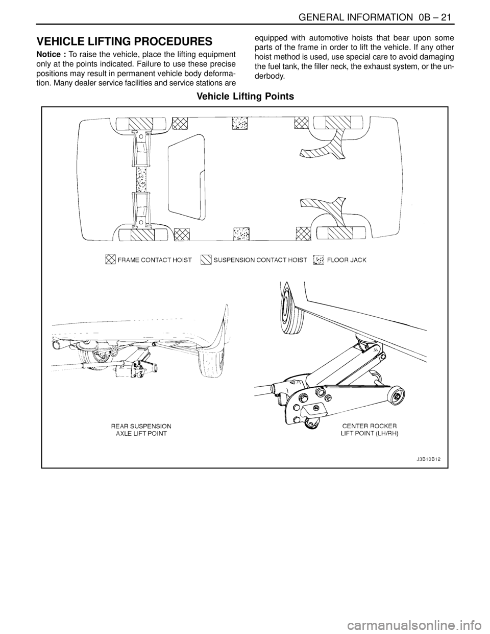
VEHICLE LIFTING PROCEDURES
Notice : To raise the vehicle, place the lifting equipment
only at the points indicated. Failure to use these precise
positions may result in permanent vehicle body deforma-
tion. Many dealer service facilities and service stations areequipped with automotive hoists that bear upon some
parts of the frame in order to lift the vehicle. If any other
hoist method is used, use special care to avoid damaging
the fuel tank, the filler neck, the exhaust system, or the un-
derbody.
Vehicle Lifting Points
Page 29 of 2643

0B – 22IGENERAL INFORMATION
DAEWOO V–121 BL4
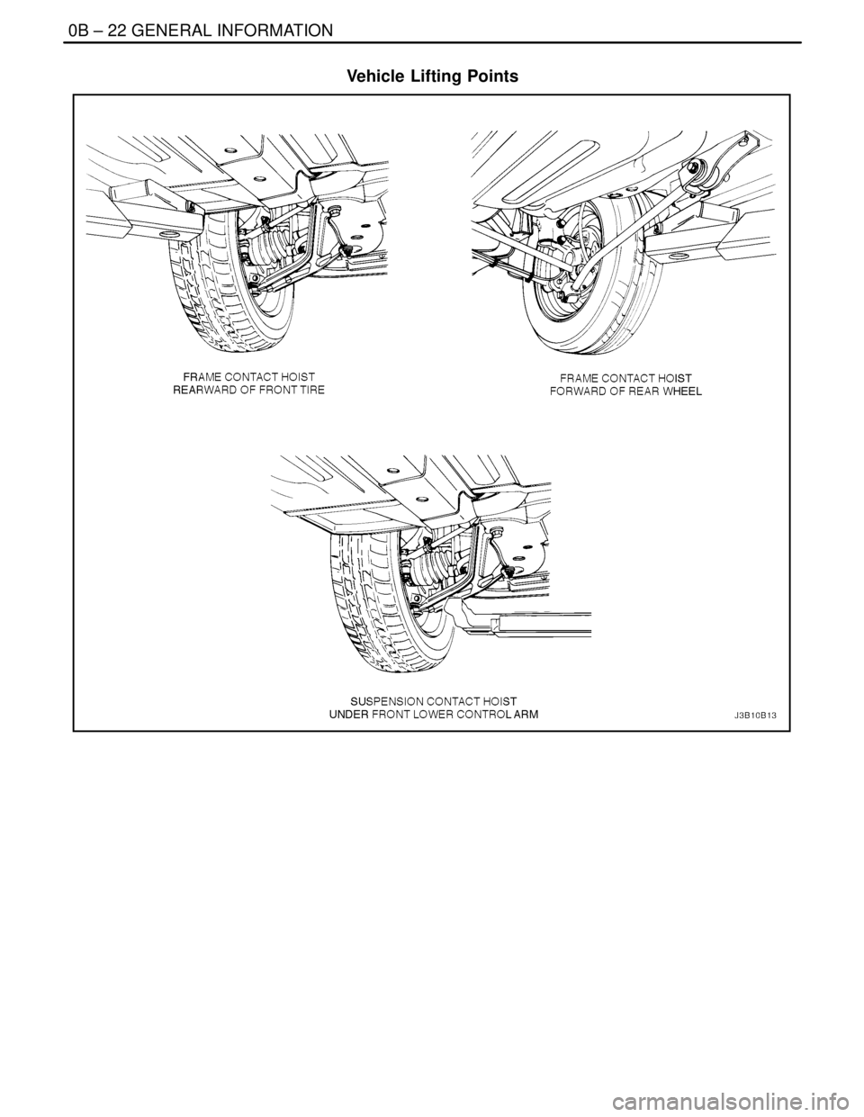
Vehicle Lifting Points
Page 234 of 2643

1E – 20IENGINE ELECTRICAL
DAEWOO V–121 BL4
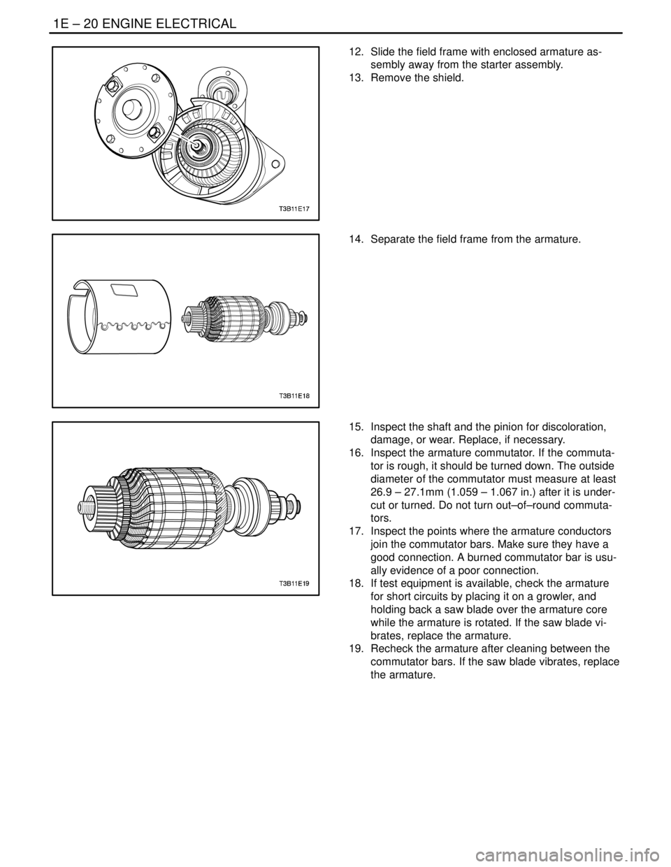
12. Slide the field frame with enclosed armature as-
sembly away from the starter assembly.
13. Remove the shield.
14. Separate the field frame from the armature.
15. Inspect the shaft and the pinion for discoloration,
damage, or wear. Replace, if necessary.
16. Inspect the armature commutator. If the commuta-
tor is rough, it should be turned down. The outside
diameter of the commutator must measure at least
26.9 – 27.1mm (1.059 – 1.067 in.) after it is under-
cut or turned. Do not turn out–of–round commuta-
tors.
17. Inspect the points where the armature conductors
join the commutator bars. Make sure they have a
good connection. A burned commutator bar is usu-
ally evidence of a poor connection.
18. If test equipment is available, check the armature
for short circuits by placing it on a growler, and
holding back a saw blade over the armature core
while the armature is rotated. If the saw blade vi-
brates, replace the armature.
19. Recheck the armature after cleaning between the
commutator bars. If the saw blade vibrates, replace
the armature.
Page 889 of 2643

ENGINE EXHAUST 1G – 9
DAEWOO V–121 BL4
GENERAL DESCRIPTION
AND SYSTEM OPERATION
EXHAUST SYSTEM
Notice : When you are inspecting or replacing the exhaust
system components, make sure there is adequate clear-
ance from all points on the underbody to avoid possible
overheating of the floor pan and possible damage to the
passenger compartment insulation and trim materials.
CAUTION : Check the complete exhaust system and
the nearby body areas and the trunk lid for broken,
damaged, missing, or mispositioned parts, open
seams, holes, loose connections, or other deteriora-
tion which could permit hazardous exhaust fumes to
seep into the trunk or the passenger compartment.
Dust or water in the trunk may be an indication of a
problem in one of these areas. Any defects should be
corrected immediately.
MUFFLER
If holes, open seams or any deterioration is discovered
upon inspection of the front muffler and pipe assembly, the
complete assembly should be replaced. The same proce-
dure is applicable to the rear muffler assembly.
Heat shields in the front and the rear muffler assembly
positions, as well as for the catalytic converter and the
connecting pipe, protect the vehicle and the environment
from high temperatures the exhaust system develops.
CATALYTIC CONVERTERS
Notice : The catalytic converter requires the use of un-
leaded fuel only, or damage to the catalyst will result.
The catalytic converters are emission control devices add-
ed to the exhaust system to reduce pollutants from the ex-
haust pipes.
The three–way catalyst has coatings which contain palla-
dium, platinum and rhodium, which simultaneouly lower
the levels of HC, CO and NOx.
Page 1049 of 2643

SECTION : 4D
FRONT DISC BRAKES
TABLE OF CONTENTS
SPECIFICATIONS4D–1 . . . . . . . . . . . . . . . . . . . . . . . . . .
Fastener Tightening Specirications 4D–1. . . . . . . . . .
DIAGNOSIS4D–1 . . . . . . . . . . . . . . . . . . . . . . . . . . . . . . . .
Lining Inspection 4D–1. . . . . . . . . . . . . . . . . . . . . . . . . .
Rotor Inspection 4D–1. . . . . . . . . . . . . . . . . . . . . . . . . .
MAINTENANCE AND REPAIR4D–3 . . . . . . . . . . . . . . .
ON–VEHICLE SERVICE 4D–3. . . . . . . . . . . . . . . . . . . . .
Shoe and Lining 4D–3. . . . . . . . . . . . . . . . . . . . . . . . . . Caliper Assembly 4D–3. . . . . . . . . . . . . . . . . . . . . . . . . .
Rotor 4D–4. . . . . . . . . . . . . . . . . . . . . . . . . . . . . . . . . . . .
Splash Shield 4D–5. . . . . . . . . . . . . . . . . . . . . . . . . . . . .
UNIT REPAIR 4D–6. . . . . . . . . . . . . . . . . . . . . . . . . . . . . .
Caliper Overhaul 4D–6. . . . . . . . . . . . . . . . . . . . . . . . . .
GENERAL DESCRIPTION AND SYSTEM
OPERATION4D–9 . . . . . . . . . . . . . . . . . . . . . . . . . . . . . .
Disc Brake Caliper Assembly 4D–9. . . . . . . . . . . . . . . .
SPECIFICATIONS
FASTENER TIGHTENING SPECIRICATIONS
ApplicationNSmLb–FtLb–In
Brake Hose Inlet Fitting–to–Caliper Bolt4030–
Caliper Bleeder Valve8–71
Caliper–to–Steering Knuckle Mounting Bolts9570–
Retaining Frame–to–Caliper Housing Bolts2720–
Rotor–to–Front Wheel Hub Detent Screw4–35
Splash Shield–to–Steering Knuckle Screws4–35
DIAGNOSIS
LINING INSPECTION
1. Raise and suitably support the vehicle.
2. Remove the front wheels. Refer to Section 2E,
Tires and Wheels.
3. Visually check the linings for minimum thickness
and wear.
4. Measure the thickness.
Important : The minimum thickness of the inner or the
outer pad is 7 mm (0.28 inch).
5. Install the brake pads in axle sets only.
6. Install the front wheels. Refer to Section 2E, Tires
and Wheels.
7. Lower the vehicle.ROTOR INSPECTION
Thickness variation can be checked by measuring the
thickness of the rotor at four or more points around the cir-
cumference of the rotor. All measurements must be made
at the same distance in from the edge of the rotor.
A rotor that varies by more than 0.01 mm (0.0004 inch) can
cause pedal pulsations and/or front end vibration during
brake applications. A rotor that does not meet these speci-
fications should be refinished to specifications or re-
placed.
Page 1058 of 2643

SECTION : 4E1
REAR DISC BRAKES
TABLE OF CONTENTS
SPECIFICATIONS4E1–1 . . . . . . . . . . . . . . . . . . . . . . . . .
Fastener Tightening Specifications 4E1–1. . . . . . . . . .
DIAGNOSIS4E1–1 . . . . . . . . . . . . . . . . . . . . . . . . . . . . . . .
Lining Inspection 4E1–1. . . . . . . . . . . . . . . . . . . . . . . . .
Rotor Inspection 4E1–1. . . . . . . . . . . . . . . . . . . . . . . . . .
MAINTENANCE AND REPAIR4E1–3 . . . . . . . . . . . . . .
ON–VEHICLE SERVICE 4E1–3. . . . . . . . . . . . . . . . . . . .
Shoe and Lining 4E1–3. . . . . . . . . . . . . . . . . . . . . . . . . . Caliper 4E1–4. . . . . . . . . . . . . . . . . . . . . . . . . . . . . . . . . .
Rotor 4E1–5. . . . . . . . . . . . . . . . . . . . . . . . . . . . . . . . . . .
Hub and Parking Brake Shoe/Backplate 4E1–6. . . . .
UNIT REPAIR 4E1–10. . . . . . . . . . . . . . . . . . . . . . . . . . . .
Caliper Overhaul 4E1–10. . . . . . . . . . . . . . . . . . . . . . . .
GENERAL DESCRIPTION AND SYSTEM
OPERATION4E1–12 . . . . . . . . . . . . . . . . . . . . . . . . . . . .
Disc Brake Caliper Assembly 4E1–12. . . . . . . . . . . . . .
SPECIFICATIONS
FASTENER TIGHTENING SPECIFICATIONS
ApplicationNSmLb–FtLb–In
Brake Hose Inlet Bolt and Ring Seals3224–
Caliper Mounting Bolts5641–
Lower Caliper Mounting Bolt2720–
Parking Brake Shoe Hold–Down Spring As-
sembly Screw4–35
Rotor Detent Screw4–35
Hub Bolts6548–
DIAGNOSIS
LINING INSPECTION
1. Raise and suitably support the vehicle.
2. Remove the rear wheels. Refer to Section 2E, Tires
and Wheels.
3. Visually check the brake shoe linings for minimum
thickness and wear.
4. Measure the thickness.
Important : The minimum discard thickness of the brake
shoe lining is 2 mm (0.08 inch).
5. Install the shoes in axle sets only.
6. Install the rear wheels. Refer to Section 2E, Tires
and Wheels.
7. Lower the vehicle.
ROTOR INSPECTION
Brake rotors are manufactured with close tolerances for
thickness variation, flatness, and lateral runout, but pits
and grooves are created in rotors during usage. Lack of
uniformity of the braking surfaces of the rotor can cause
inadequate braking and a pulsating pedal during braking.
The surface finish of the rotor is also important because
an unsuitable surface finish can cause pulling and rapid
wear of the brake shoe lining. If a rotor does not meet the
specification, it should be refinished to specification or re-
placed. Refinishing of the rotor should only be done with
precision equipment.
Thickness variation can be checked by measuring the
thickness of the rotor at four or more points around the cir-
cumference of the rotor. All measurements must be made
at the same distance from the edge of the rotor. A rotor that
varies by more than. 1.0 mm (0.04 inch) can cause pedal
Page 1396 of 2643

ZF 4 HP 16 AUTOMATIC TRANSAXLE 5A1 – 47
DAEWOO V–121 BL4
Repairing the Fluid Leak
Once the leak point is found the source of the leak must
be determined. The following list describes the potential
causes for the leak:
S Fasteners are not torqued to specification.
S Fastener threads and fastener holes are dirty or
corroded.
S Gaskets, seals or sleeves are misarranged, dam-
aged or worn.
S Damaged, warped or scratched seal bore or gasket
surface.
S Loose or worn bearing causing excess seal or
sleeve wears.
S Case or component porosity.
S Fluid level is too high.
S Plugged vent or damaged vent tube.
S Water or coolant in fluid.
S Fluid drain back holes plugged.
ELECTRICAL/GARAGE SHIFT TEST
This preliminary test should be performed before a hoist
or road test to make sure electronic control inputs is con-
nected and operating. If the inputs are not checked before
operating the transaxle, a simple electrical condition could
be misdiagnosed as a major transaxle condition.
A scan tool provides valuable information and must be
used on the automatic transaxle for accurate diagnosis.
1. Move gear selector to P (Park) and set the parking
brake.
2. Connect scan tool to Data Link Connector (DLC)
terminal.
3. Start engine.
4. Turn the scan tool ON.
5. Verify that the appropriate signals are present.
These signals may include:
S ENGINE SPEED
S VEHICLE SPEED
S THROTTLE POSITION
S TRANSAXLE GEAR STATE
S GEAR SHIFT LEVER POSITION
S TRANSAXLE FLUID TEMPERATURE
S CLOSED THROTTLE POSITION LEARN
S OPEN THROTTLE POSITION LEARNT
S CLOSED ACCEL. PEDAL POSITION LEARNT
S OPEN ACCEL. PEDAL POSITION LEARNT
S A/C COMPRESSOR STATUS
S MODE SWITCH
S THROTTLE POSITION VOLTAGE
S GEAR SHIFT LEVER POSITION VOLTAGE
S TRANS. FLUID TEMPERATURE VOLTAGE
S A/C SWITCH
S MODE SWITCH VOLTAGE
S BATTERY VOLTAGE
6. Monitor the A/C COMPRESSOR STATUS signal
while pushing the A/C switch.S The A/C COMPRESSOR STATUS should come
ON when the A/C switch is pressed, and turns
OFF when the A/C switch is repushed.
7. Monitor the GEAR SHIFT LEVER POSITION signal
and move the gear shift control lever through all the
ranges.
S Verify that the GEAR SHIFT LEVER POSITION
value matches the gear range indicated on the
instrument panel or console.
S Gear selections should be immediate and not
harsh.
8. Move gear shift control lever to neutral and monitor
the THROTTLE POSITION signal while increasing
and decreasing engine speed with the accelerator
pedal.
S THROTTLE POSITION should increase with
engine speed.
ROAD TEST PROCEDURE
S Perform the road test using a scan tool.
S This test should be performed when traffic and road
conditions permit.
S Observe all traffic regulations.
The TCM calculates upshift points based primarily on two
inputs : throttle angle and vehicle speed. When the TCM
wants a shift to occur, an electrical signal is sent to the shift
solenoids which in turn moves the valves to perform the
upshift.
The shift speed charts reference throttle angle instead of
”min throttle” or ”wot” to make shift speed measurement
more uniform and accurate. A scan tool should be used to
monitor throttle angle. Some scan tools have been pro-
grammed to record shift point information. Check the
introduction manual to see if this test is available.
Upshift Procedure
With gear selector in drive(D)
1. Look at the shift speed chart contained in this sec-
tion and choose a percent throttle angle of 10 or
25%.
2. Set up the scan tool to monitor throttle angle and
vehicle speed.
3. Accelerate to the chosen throttle angle and hold the
throttle steady.
4. As the transaxle upshifts, note the shift speed and
commanded gear changes for :
S Second gear.
S Third gear.
S Fourth gear.
Important : Shift speeds may vary due to slight hydraulic
delays responding to electronic controls. A change from
the original equipment tire size affects shift speeds.
Note when TCC applies. This should occur in fourth gear.
If the apply is not noticed by an rpm drop, refer to the
”Lock–up Clutch Diagnosis” information contained in this
section.