2004 DAEWOO LACETTI turn signal
[x] Cancel search: turn signalPage 1962 of 2643

6E – 8ISTEERING WHEEL AND COLUMN
DAEWOO V–121 BL4
MAINTENANCE AND REPAIR
ON–VEHICLE SERVICE
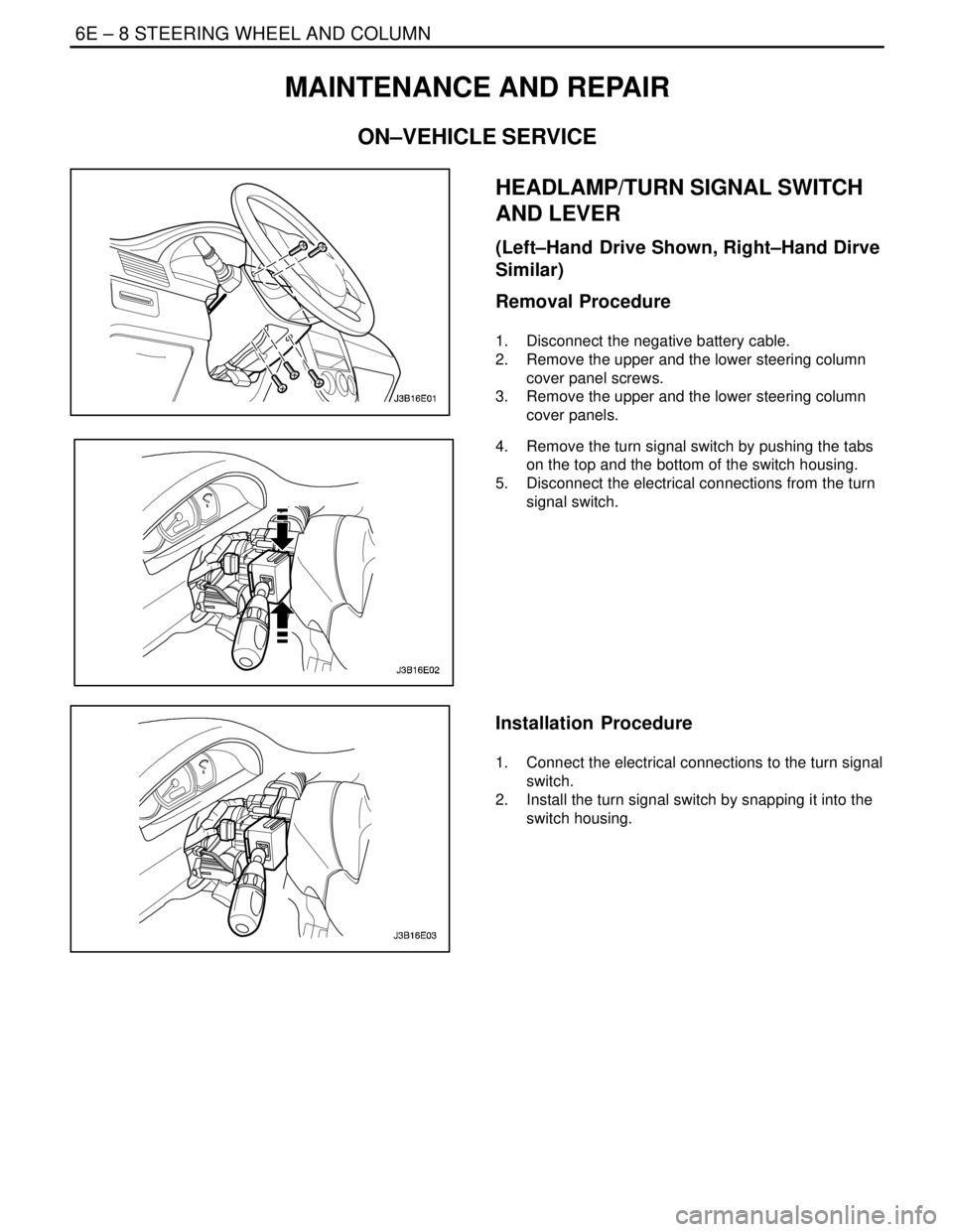
HEADLAMP/TURN SIGNAL SWITCH
AND LEVER
(Left–Hand Drive Shown, Right–Hand Dirve
Similar)
Removal Procedure
1. Disconnect the negative battery cable.
2. Remove the upper and the lower steering column
cover panel screws.
3. Remove the upper and the lower steering column
cover panels.
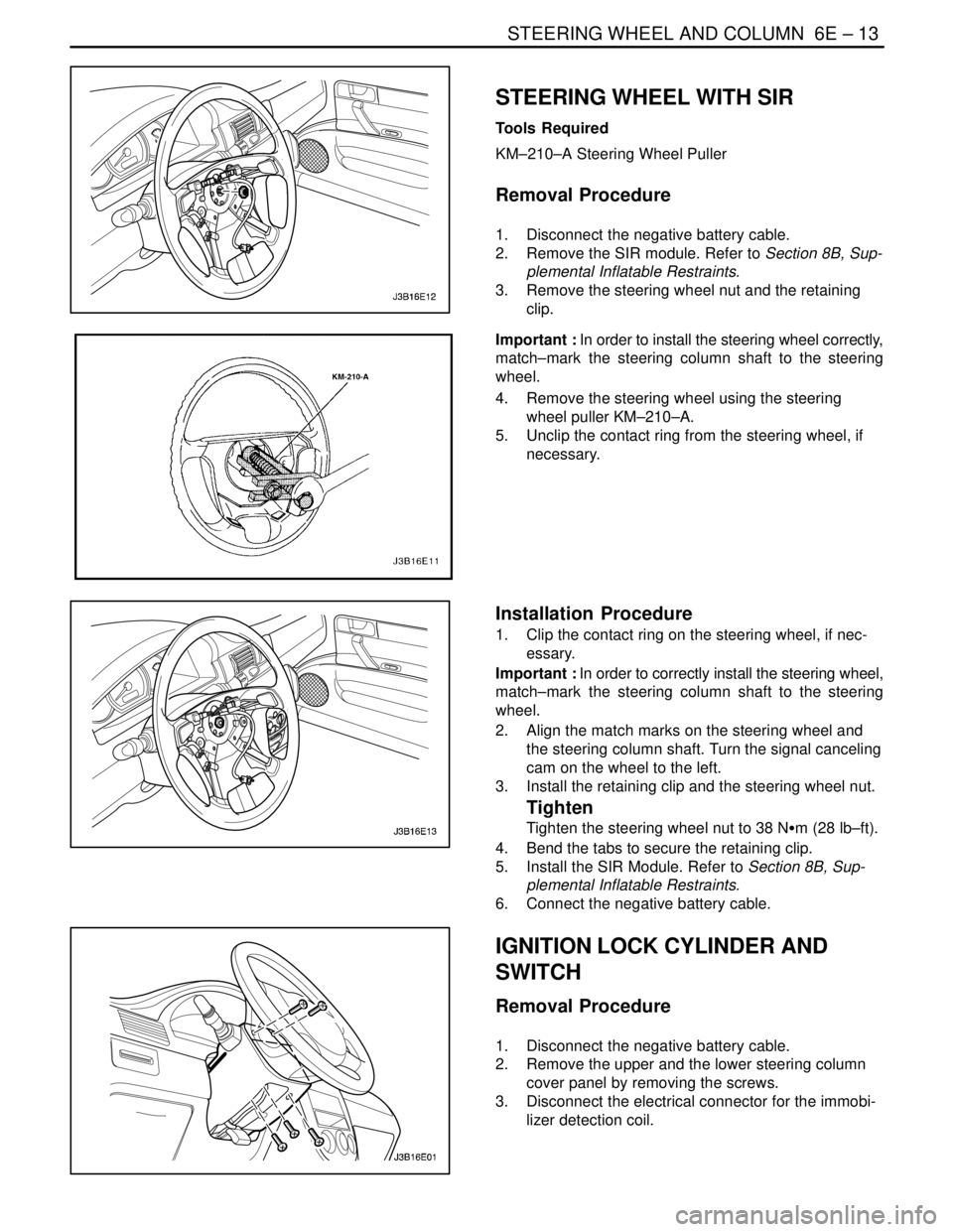
4. Remove the turn signal switch by pushing the tabs
on the top and the bottom of the switch housing.
5. Disconnect the electrical connections from the turn
signal switch.
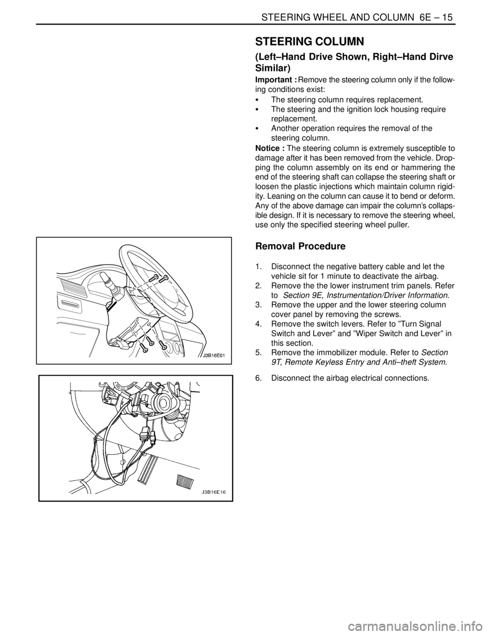
Installation Procedure
1. Connect the electrical connections to the turn signal
switch.
2. Install the turn signal switch by snapping it into the
switch housing.
Page 1967 of 2643

STEERING WHEEL AND COLUMN 6E – 13
DAEWOO V–121 BL4
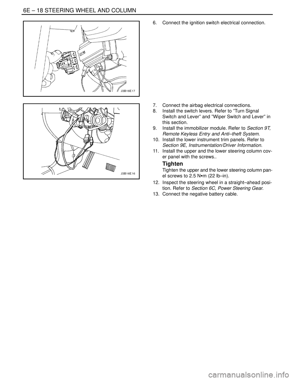
STEERING WHEEL WITH SIR
Tools Required
KM–210–A Steering Wheel Puller
Removal Procedure
1. Disconnect the negative battery cable.
2. Remove the SIR module. Refer to Section 8B, Sup-
plemental Inflatable Restraints.
3. Remove the steering wheel nut and the retaining
clip.
Important : In order to install the steering wheel correctly,
match–mark the steering column shaft to the steering
wheel.
4. Remove the steering wheel using the steering
wheel puller KM–210–A.
5. Unclip the contact ring from the steering wheel, if
necessary.
Installation Procedure
1. Clip the contact ring on the steering wheel, if nec-
essary.
Important : In order to correctly install the steering wheel,
match–mark the steering column shaft to the steering
wheel.
2. Align the match marks on the steering wheel and
the steering column shaft. Turn the signal canceling
cam on the wheel to the left.
3. Install the retaining clip and the steering wheel nut.
Tighten
Tighten the steering wheel nut to 38 NSm (28 lb–ft).
4. Bend the tabs to secure the retaining clip.
5. Install the SIR Module. Refer to Section 8B, Sup-
plemental Inflatable Restraints.
6. Connect the negative battery cable.
IGNITION LOCK CYLINDER AND
SWITCH
Removal Procedure
1. Disconnect the negative battery cable.
2. Remove the upper and the lower steering column
cover panel by removing the screws.
3. Disconnect the electrical connector for the immobi-
lizer detection coil.
Page 1969 of 2643

STEERING WHEEL AND COLUMN 6E – 15
DAEWOO V–121 BL4
STEERING COLUMN
(Left–Hand Drive Shown, Right–Hand Dirve
Similar)
Important : Remove the steering column only if the follow-
ing conditions exist:
S The steering column requires replacement.
S The steering and the ignition lock housing require
replacement.
S Another operation requires the removal of the
steering column.
Notice : The steering column is extremely susceptible to
damage after it has been removed from the vehicle. Drop-
ping the column assembly on its end or hammering the
end of the steering shaft can collapse the steering shaft or
loosen the plastic injections which maintain column rigid-
ity. Leaning on the column can cause it to bend or deform.
Any of the above damage can impair the column’s collaps-
ible design. If it is necessary to remove the steering wheel,
use only the specified steering wheel puller.
Removal Procedure
1. Disconnect the negative battery cable and let the
vehicle sit for 1 minute to deactivate the airbag.
2. Remove the the lower instrument trim panels. Refer
to Section 9E, Instrumentation/Driver Information.
3. Remove the upper and the lower steering column
cover panel by removing the screws.
4. Remove the switch levers. Refer to ”Turn Signal
Switch and Lever” and ”Wiper Switch and Lever” in
this section.
5. Remove the immobilizer module. Refer to Section
9T, Remote Keyless Entry and Anti–theft System.
6. Disconnect the airbag electrical connections.
Page 1972 of 2643

6E – 18ISTEERING WHEEL AND COLUMN
DAEWOO V–121 BL4
6. Connect the ignition switch electrical connection.
7. Connect the airbag electrical connections.
8. Install the switch levers. Refer to ”Turn Signal
Switch and Lever” and ”Wiper Switch and Lever” in
this section.
9. Install the immobilizer module. Refer to Section 9T,
Remote Keyless Entry and Anti–theft System.
10. Install the lower instrument trim panels. Refer to
Section 9E, Instrumentation/Driver Information.
11. Install the upper and the lower steering column cov-
er panel with the screws..
Tighten
Tighten the upper and the lower steering column pan-
el screws to 2.5 NSm (22 lb–in).
12. Inspect the steering wheel in a straight–ahead posi-
tion. Refer to Section 6C, Power Steering Gear.
13. Connect the negative battery cable.
Page 1974 of 2643

6E – 20ISTEERING WHEEL AND COLUMN
DAEWOO V–121 BL4
GENERAL DESCRIPTION
AND SYSTEM OPERATION
STEERING WHEEL AND COLUMN
CAUTION : To ensure the energy–absorbing action of
the steering column, it is important to use only the
specified screws, bolts, and nuts, tightened to the
specified torque.
In addition to the steering function, the steering column
provides safety and security.
The energy–absorbing column is designed to compress in
a front–end collision to lessen the chance of driver injury.
The ignition switch and the lock are mounted on the col-
umn, allowing the ignition and steering operations to be
locked to inhibit theft of the car.
The column levers trigger the turn signals, the headlight
beams, and the windshield washer and wipers.The tilt steering column uses telescopic function to allow
the steering wheel to tilt up and down in and out. This en-
ables the driver to adjust the steering wheel to a comfort-
able position.
Notice : Apply a thin coat of lithium grease to all friction
points when reassembling.
The column may be disassembled and reassembled easi-
ly.IGNITION KEY REMINDER
The ignition key reminder alerts the driver that the key is
still in the ignition when the driver attempts to exit the ve-
hicle.
An internal switch in the ignition lock cylinder supplies bat-
tery voltage to the reminder chime module when all of the
following conditions are true:
S The key is in the ignition switch.
S The ignition is OFF.
S The driver’s door is open.
For information on removal and installation of the reminder
chime module, refer to Section 9E, Instrumentation/Driver
Information.
Page 2054 of 2643

7B – 52IMANUAL CONTROL HEATING, VENTILATION AND AIR CONDITIONING SYSTEM
DAEWOO V–121 BL4
SYSTEM COMPONENTS–CONTROL
Controller
The operation of the A/C system is controlled by the
switches and the lever on the control head. The compres-
sor clutch and the blower are connected electrically to the
control head by a wiring harness. The blower circuit is
open in the OFF mode. Airflow is provided by the four
blower speeds available in the remaining modes. Cooled
and dehumidified air is available in the MAX, NORMAL,
BI–LEVEL, and DEFROST modes.
The temperature is controlled by the position of the tem-
perature knob on the control head. A cable connects this
knob to the temperature door, which controls the airflow
through the heater core. As the temperature knob is
moved through its range of travel, a sliding clip on the
cable at the temperature valve connection should assume
a position ensuring that the temperature door will seat in
both extreme positions. The temperature door position is
independent of the mode control switch. The temperature
door on some models is controlled electrically, eliminating
the need for the temperature cable.
The electric engine cooling fan on some vehicles is not
part of the A/C control system; however, the fan is opera-
tional any time the A/C control is in the MAX, NORMAL,
or BI–LEVEL modes. Some models provide for engine
cooling fan operation when the controller is in the DE-
FROST mode. This added feature is part of the A/C con-
troller function and is aimed at preventing excessive com-
pressor head temperatures. It also allows the A/C system
to function more efficiently. On some models, the engine
cooling fan will be turned off during road speed conditions
above 56 km/h (35 mph), when the airflow though the con-
denser coil is adequate for efficient cooling. The operation
of the cooling fan is controlled by the powertrain control
module (PCM), or the engine control module (ECM),
through the cooling fan relay.
Pressure Transducer
The pressure transducer incorporates the functions of the
high–pressure and the low–pressure cutout switches
along with the fan cycling switch. The pressure transducer
is located in the high–side liquid refrigerant line near the
right front strut tower and the air filter assembly.
Wide–Open Throttle (WOT) Compressor
Cutoff
During full throttle acceleration on vehicles equipped with
multi–port injection (MPI), the throttle position sensor
(TPS) sends a signal to the PCM or the ECM, which then
controls the compressor clutch.
A/C Time Delay Relay
This relay on some vehicles controls the current to the en-
tire A/C system and provides a short delay of A/C opera-
tion upon start–up.
V5 COMPRESSOR–GENERAL
DESCRIPTION
Different vehicles with V5 compressors may exhibit differ-
ences in mounting and installation, but overhaul proce-
dures are similar.
Before removing the compressor or performing on–ve-
hicle repairs, clean the compressor connections and the
outside of the compressor.
Important : After removing a compressor from the vehicle
for servicing, drain the oil by removing the oil drain plug.
Also drain the oil from the suction and the discharge ports
to insure complete draining. Measure the amount of oil
drained, and record that amount. Discard the used oil and
add the same amount of new polyalkaline glycol (PAG) re-
frigerant oil to the compressor.
The compressor has been removed from the vehicle un-
less otherwise indicated.
Clean tools and a clean work area are important for proper
servicing. Keep dirt and foreign material from getting on or
into the compressor parts. Parts that are to be reassem-
bled should be cleaned with trichloroethane, naphtha,
stoddard solvent, kerosene, or equivalent solvents. Dry
the cleaned parts with clean dry air. Use only lint–free
cloths to wipe the parts.
V5 COMPRESSOR–DESCRIPTION OF
OPERATION
The V5 is a variable displacement compressor that can
match the automotive air conditioning (A/C) demand un-
der all conditions without cycling. The basic compressor
mechanism is a variable angle wobble–plate with five ax-
ially oriented cylinders. The center of control of the com-
pressor displacement is a bellows–actuated control valve
located in the rear head of the compressor. The control
valve senses compressor suction pressure.
The wobble–plate angle and the compressor displace-
ment are controlled by the crankcase suction pressure dif-
ferential. When the A/C capacity demand is high, the suc-
tion pressure will be above the control point. The valve will
maintain a bleed from crankcase to suction. With no
crankcase suction pressure differential, the compressor
will have maximum displacement.
When the A/C capacity demand is lower and the suction
pressure reaches the control point, the valve will bleed dis-
charge gas into the crankcase and close off a passage
from the crankcase to the suction plenum. The angle of the
wobble–plate is controlled by a force balance on the five
pistons. A slight elevation of the crankcase suction pres-
sure differential creates total force on the pistons resulting
in a movement about the wobbleplate pivot pin that re-
duces the plate angle.
The compressor has a unique lubrication system. The
crankcase suction bleed is routed through the rotating
wobble–plate for lubrication of the wobble–plate bearing.
The rotation acts as an oil separator which removes some
Page 2095 of 2643

7D – 40IAUTOMATIC TEMPERATURE CONTROL HEATING, VENTILATION, AND AIR CONDITIONING SYSTEM
DAEWOO V–121 BL4
GENERAL DESCRIPTION
AND SYSTEM OPERATION
GENERAL INFORMATION
THE V5 SYSTEM
Refer to Section 7B, Manual Control Heating, Ventilation,
and Air Conditioning System,for general information de-
tails for the following:
S System Components – Functional.
S The V5 A/C System.
S V5 Compressor – Description of Operation.
S V5 Compressor – General Description.
SYSTEM COMPONENTS–CONTROL
Controller
The operation of the A/C system is controlled by the
switches on the control head. This console–mounted
heating and ventilation system contains the following
knobs and display:
Temperature Control Push Knobs
1. Raise the temperature of the air entering the ve-
hicle by pressing the top switch, with the red arrow
pointing upward.
2. Lower the temperature by pressing the bottom
switch, with the blue arrow pointing downward.
3. Actuate the air mix door by an electric motor.
4. Vary the mix of the air passing through the heater
core with the air bypassing the core.
Each press of a switch changes the set temperature by in-
crements of 0.5°C (1°F). This is shown in the temperature
window on the function display.
The Function Display
This is an LCD display indicating the status of the control
settings selected. Starting from the left end of the display,
the sections are as follows:
1. Temperature setting – Indicates the temperature set
with the temperature control knob.
2. Auto status – Indicates whether the system is oper-
ating in the full auto mode or the manual mode.
3. Defroster icon – Indicates manual selection of full
defrost mode.
4. Mode – Indicated by icon, the mode chosen by the
system in auto (or by the operator in manual) is
shown by an illumination arrow indicating the air
path.
5. A/C – A snowflake icon indicating whether the A/C
is ON or OFF.
6. Fan speed – Indicates the fan speed by illuminating
a bar based on the segment at the front, for low
speed, and adding additional segments in order up
to the fifth, for high speed.Eight Additional Push Knobs
1. Full defrost – Causes the mode motors to direct all
air to the windshield and aide window outlets for
maximum defrosting.
2. Air intake – Switches between fresh air intake, the
default, and recirculating air. Airflow arrows on the
display indicate the mode in effect.
3. Full Auto Switch – Maintains the set temperature
automatically. In this mode, the fully automatic tem-
perature control (FATC) system controls the follow-
ing:
S The air mix door motor.
S The mode door motor.
S The blower motor speed.
S The inlet air door motor.
S A/C ON/OFF.
4. OFF Switch – Turns the automatic air conditioning
and fan control off.
5. Mode Switch – Allows manual selection of the air-
flow direction.
S Selection is shown on the function display.
S Each time the mode switch is pressed, the next
function is displayed.
6. A/C Switch – Allows manual selection and control
of the air conditioning function.
7. Fan Control Switch – Allows manual selection
among five fan speeds.
8. Defogger Switch – Turns on the electric defogging
heater in the rear window and the outside rearview
mirrors, if the vehicle is equipped with heated mir-
rors.
Pressure Transducer
Pressure transducer switching incorporates the functions
of the high–pressure and the low–pressure cutout
switches along with the fan cycling switch. The pressure
transducer is located in the high–side liquid refrigerant line
behind the right strut tower, between the right strut tower
and the fire wall. The output from this pressure transducer
goes to the electronic control module (ECM), which con-
trols the compressor function based on the pressure sig-
nal.
Wide–Open Throttle (WOT) Compressor
Cutoff
During full–throttle acceleration, the throttle position sen-
sor (TPS) sends a signal to the ECM, which then controls
the compressor clutch.
High RPM Cutoff
As engine rpm approaches the maximum limit, the ECM
will disengage the compressor clutch until the engine
slows to a lower rpm.
Page 2227 of 2643

SECTION : 9B
LIGHTING SYSTEMS
CAUTION : Disconnect the negative battery cable before removing or installing any electrical unit or when a tool
or equipment could easily come in contact with exposed electrical terminals. Disconnecting this cable will help
prevent personal injury and damage to the vehicle. The ignition must also be in LOCK unless otherwise noted.
TABLE OF CONTENTS
SPECIFICATIONS9B–2 . . . . . . . . . . . . . . . . . . . . . . . . . .
Bulb Usage Chart 9B–2. . . . . . . . . . . . . . . . . . . . . . . . . .
Fastener Tightening Specifications 9B–2. . . . . . . . . . .
SCHEMATIC AND ROUTING DIAGRAMS9B–3 . . . . .
Backup Lamps Circuit 9B–3. . . . . . . . . . . . . . . . . . . . . .
Instruments Circuit (W/O Dimmer Control :
General Only) 9B–4. . . . . . . . . . . . . . . . . . . . . . . . . . .
Instruments Circuit (W/ Dimmer Control) 9B–5. . . . . .
Front And Rear Fog Lamps Circuit 9B–6. . . . . . . . . . .
Headlamps–On Reminder Chime Circuit 9B–7. . . . . .
Headlamps and Headlamp Leveling Circuit 9B–8. . . .
Daytime Running Lamps Circuit 9B–9. . . . . . . . . . . . .
Parking, Tail and License Lamps Circuit 9B–10. . . . . .
Stoplamps Circuit 9B–11. . . . . . . . . . . . . . . . . . . . . . . . .
Turn and Hazard Lamps Circuit 9B–12. . . . . . . . . . . . .
Interior Courtesy and Luggage Compartment Lamp
Circuit 9B–13. . . . . . . . . . . . . . . . . . . . . . . . . . . . . . . . .
DIAGNOSIS9B–14 . . . . . . . . . . . . . . . . . . . . . . . . . . . . . . .
Headlamps–On Reminder Chime 9B–14. . . . . . . . . . .
Headlamps 9B–16. . . . . . . . . . . . . . . . . . . . . . . . . . . . . .
Headlamp Leveling 9B–20. . . . . . . . . . . . . . . . . . . . . . .
Daytime Running Lamps 9B–22. . . . . . . . . . . . . . . . . . .
Parking Lamps and Taillamps 9B–23. . . . . . . . . . . . . .
Interior Courtesy and Luggage Compartment
Lamps 9B–31. . . . . . . . . . . . . . . . . . . . . . . . . . . . . . . . .
Fog Lamps 9B–34. . . . . . . . . . . . . . . . . . . . . . . . . . . . . .
MAINTENANCE AND REPAIR9B–36 . . . . . . . . . . . . . .
ON–VEHICLE SERVICE 9B–36. . . . . . . . . . . . . . . . . . . . Headlamps/Front Turn Signal Lamps 9B–36. . . . . . . .
Daytime Running Lamp Module 9B–37. . . . . . . . . . . . .
Parking Lamps 9B–37. . . . . . . . . . . . . . . . . . . . . . . . . . .
Side Turn Signal Lamps 9B–38. . . . . . . . . . . . . . . . . . .
Front Fog Lamps 9B–38. . . . . . . . . . . . . . . . . . . . . . . . .
Notchback Rear Combination Lamps 9B–39. . . . . . . .
Hatchback Rear Combination Lamps 9B–40. . . . . . . .
Hatchback Extension Lamps 9B–40. . . . . . . . . . . . . . .
Notchback Center High–Mounted Stoplamp 9B–41. .
Hatchback Center High–Mounted Stoplamp 9B–41. .
License Plate Lamps 9B–42. . . . . . . . . . . . . . . . . . . . . .
Door Jamb Switch 9B–42. . . . . . . . . . . . . . . . . . . . . . . .
Center Room Lamp 9B–43. . . . . . . . . . . . . . . . . . . . . . .
Map Lamp 9B–43. . . . . . . . . . . . . . . . . . . . . . . . . . . . . . .
Luggage Compartment Lamp 9B–44. . . . . . . . . . . . . . .
Ashtray and Cigar Lighter Lamp 9B–44. . . . . . . . . . . .
GENERAL DESCRIPTION AND SYSTEM
OPERATION9B–46 . . . . . . . . . . . . . . . . . . . . . . . . . . . . .
Headlamps–On Reminder Chime 9B–46. . . . . . . . . . .
Headlamps 9B–46. . . . . . . . . . . . . . . . . . . . . . . . . . . . . .
Daytime Running Lamps 9B–46. . . . . . . . . . . . . . . . . . .
Parking and Turn Signal Lamps 9B–46. . . . . . . . . . . . .
Fog Lamps 9B–46. . . . . . . . . . . . . . . . . . . . . . . . . . . . . .
Rear Combination Lamps 9B–46. . . . . . . . . . . . . . . . . .
License Plate Lamp 9B–46. . . . . . . . . . . . . . . . . . . . . . .
Interior Courtesy Lamp 9B–46. . . . . . . . . . . . . . . . . . . .
Luggage Compartment Lamp 9B–46. . . . . . . . . . . . . . .
Backup Lamps 9B–47. . . . . . . . . . . . . . . . . . . . . . . . . . .