Page 840 of 2643

1F – 594IENGINE CONTROLS
DAEWOO V–121 BL4
MAINTENANCE AND REPAIR
ON–VEHICLE SERVICE
FUEL SYSTEM PRESSURE RELIEF
Procedure
CAUTION : The fuel system is under pressure. To
avoid fuel spillage and the risk of personal injury or
fire, it is necessary to relieve the fuel system pressure
before disconnecting the fuel lines.
1. Remove the fuel cap.
2. Remove the fuel pump fuse Ef18 from the engine
fuse block.
3. Start the engine and allow the engine to stall.
4. Crank the engine for an additional 10 seconds.
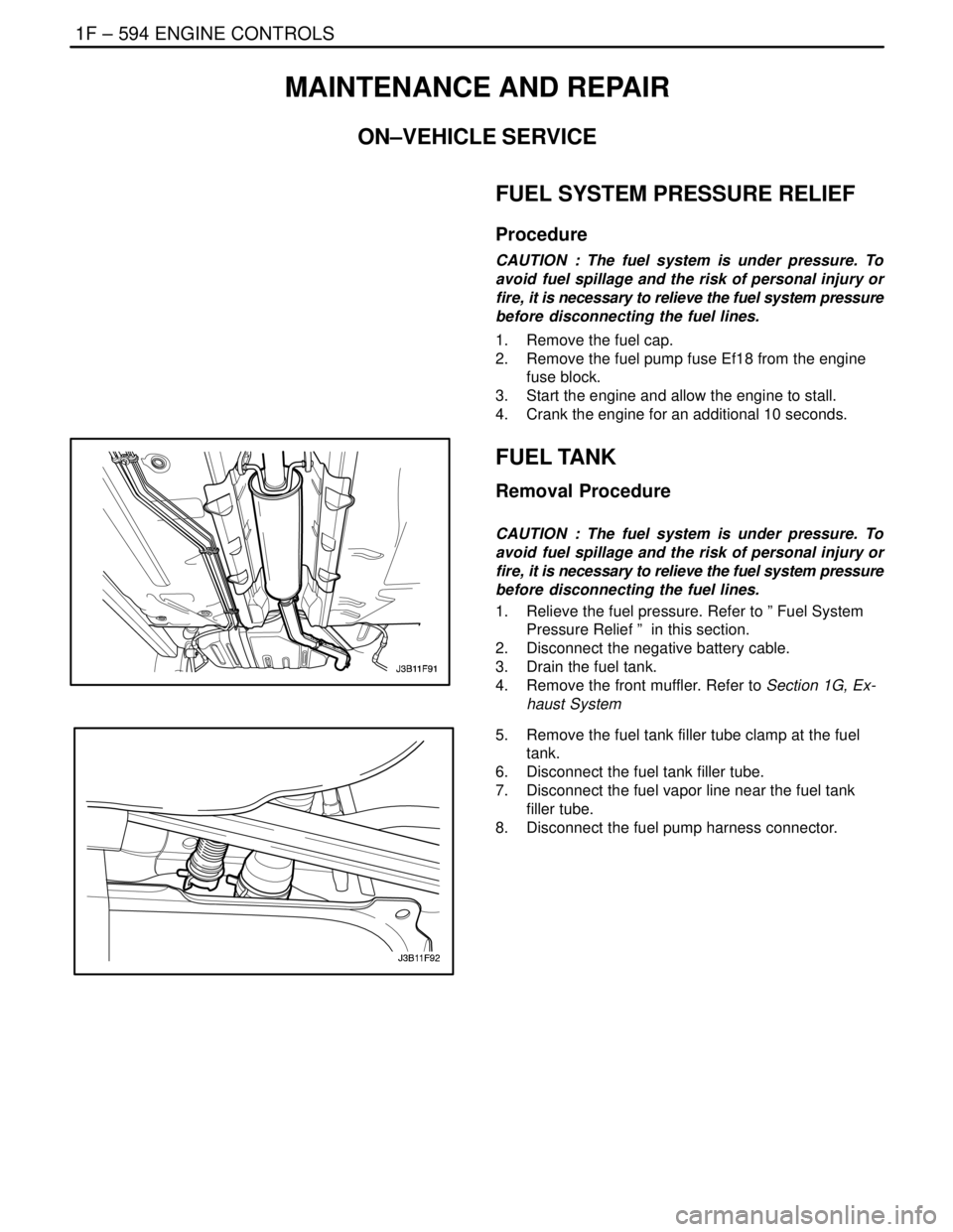
FUEL TANK
Removal Procedure
CAUTION : The fuel system is under pressure. To
avoid fuel spillage and the risk of personal injury or
fire, it is necessary to relieve the fuel system pressure
before disconnecting the fuel lines.
1. Relieve the fuel pressure. Refer to ” Fuel System
Pressure Relief ” in this section.
2. Disconnect the negative battery cable.
3. Drain the fuel tank.
4. Remove the front muffler. Refer to Section 1G, Ex-
haust System
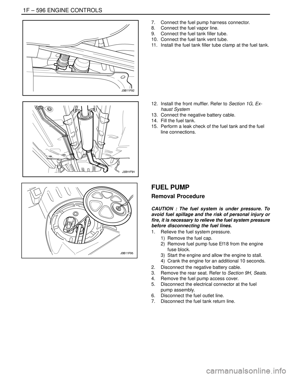
5. Remove the fuel tank filler tube clamp at the fuel
tank.
6. Disconnect the fuel tank filler tube.
7. Disconnect the fuel vapor line near the fuel tank
filler tube.
8. Disconnect the fuel pump harness connector.
Page 841 of 2643
ENGINE CONTROLS 1F – 595
DAEWOO V–121 BL4
9. Disconnect the fuel inlet line and the fuel return line
near the right front of the fuel tank.
10. Remove the Fuel pump. Refer to ”Fuel Pump” in
this section.
11. Remove the parking brake cables support brackets.
12. Support the fuel tank.
13. Remove the fuel tank strap retaining nuts.
14. Remove the fuel tank strap.
15. Carefully lower the fuel tank.
16. Remove the fuel tank.
17. Transfer any parts as needed.
Installation Procedure
1. Raise the fuel tank into position.
2. Install the fuel tank straps.
3. Install the fuel tank strap retaining nuts.
Tighten
Tighten the fuel tank strap retaining nuts to 20 NSm
(15 lb–ft).
4. Install the parking brake cables support bracket.
5. Install the fuel pump. Refer to ”Fuel Pump” in this
section.
6. Connect the fuel outlet line and the fuel return line.
Page 842 of 2643

1F – 596IENGINE CONTROLS
DAEWOO V–121 BL4
7. Connect the fuel pump harness connector.
8. Connect the fuel vapor line.
9. Connect the fuel tank filler tube.
10. Connect the fuel tank vent tube.
11. Install the fuel tank filler tube clamp at the fuel tank.
12. Install the front muffler. Refer to Section 1G, Ex-
haust System
13. Connect the negative battery cable.
14. Fill the fuel tank.
15. Perform a leak check of the fuel tank and the fuel
line connections.
FUEL PUMP
Removal Procedure
CAUTION : The fuel system is under pressure. To
avoid fuel spillage and the risk of personal injury or
fire, it is necessary to relieve the fuel system pressure
before disconnecting the fuel lines.
1. Relieve the fuel system pressure.
1) Remove the fuel cap.
2) Remove fuel pump fuse Ef18 from the engine
fuse block.
3) Start the engine and allow the engine to stall.
4) Crank the engine for an additional 10 seconds.
2. Disconnect the negative battery cable.
3. Remove the rear seat. Refer to Section 9H, Seats.
4. Remove the fuel pump access cover.
5. Disconnect the electrical connector at the fuel
pump assembly.
6. Disconnect the fuel outlet line.
7. Disconnect the fuel tank return line.
Page 843 of 2643

ENGINE CONTROLS 1F – 597
DAEWOO V–121 BL4
8. Turn the lock ring counterclockwise to clear the
tank tabs.
9. Remove the fuel pump assembly from the tank.
Installation Procedure
1. Clean the gasket mating surface on the fuel tank.
2. Position the new gasket in place.
3. Install the fuel pump into the fuel tank in the same
location as removed for ease of line and connector
installation.
4. Position the lock ring in place and turn it clockwise
until it contacts the tank stop.
5. Connect the fuel pump assembly connector.
6. Install the fuel pump outlet line.
7. Install the fuel tank return line.
8. Install the fuel pump access cover.
9. Connect the negative battery cable.
10. Perform an operational check of the fuel pump.
11. Install the rear seat. Refer to Section 9H, Seats.
FUEL FILTER
Removal Procedure
CAUTION : The fuel system is under pressure. To
avoid fuel spillage and the risk of personal injury or
fire, it is necessary to relieve the fuel system pressure
before disconnecting the fuel lines.
1. Relieve the fuel system pressure. Refer to ” Fuel
System Pressure Relief ” in this section.
2. Disconnect the negative battery cable.
3. Remove the fuel filter mounting bracket assembly
bolt.
4. Remove the fuel filter cover.
5. Disconnect the inlet/outlet fuel lines by moving the
line connector lock forward and pulling the hose off
of the fuel filter tube.
Page 844 of 2643

1F – 598IENGINE CONTROLS
DAEWOO V–121 BL4
Installation Procedure
1. Install the new fuel filter into the retaining clamp.
Note the flow direction.
2. Install the fuel filter.
3. Connect the inlet/outlet lines. Secure the lines with
the connector lock.
4. Install the fuel filter cover.
5. Install the fuel filter mounting bracket assembly bolt
with the fuel filter ground.
Tighten
Tighten the fuel filter mounting bracket assembly
bolts to 4 NSm (35 lb–ft).
6. Connect the negative battery cable.
7. Perform a leak test of the fuel filter.
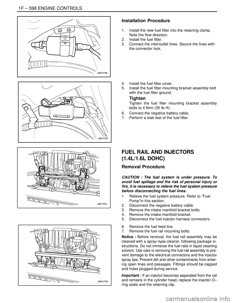
FUEL RAIL AND INJECTORS
(1.4L/1.6L DOHC)
Removal Procedure
CAUTION : The fuel system is under pressure. To
avoid fuel spillage and the risk of personal injury or
fire, it is necessary to relieve the fuel system pressure
before disconnecting the fuel lines.
1. Relieve the fuel system pressure. Refer to ”Fuel
Pump”in this section.
2. Disconnect the negative battery cable.
3. Remove the intake manifold bracket bolts.
4. Remove the intake manifold bracket.
5. Disconnect the fuel injector harness connectors.
6. Remove the fuel feed line.
7. Remove the fuel rail mounting bolts.
Notice : Before removal, the fuel rail assembly may be
cleaned with a spray–type cleaner, following package in-
structions. Do not immerse the fuel rails in liquid cleaning
solvent. Use care in removing the fuel rail assembly to pre-
vent damage to the electrical connectors and the injector
spray tips. Prevent dirt and other contaminants from enter-
ing open lines and passages. Fittings should be capped
and holes plugged during service.
Important : If an injector becomes separated from the rail
and remains in the cylinder head, replace the injector O–
ring seals and the retaining clip.
Page 846 of 2643

1F – 600IENGINE CONTROLS
DAEWOO V–121 BL4
7. Connect the fuel feed hose.
8. Connect the fuel injector harness connectors. Ro-
tate each fuel injector as required to avoid stretch-
ing the wireing harness.
9. Install the intake manifold bracket with the bolts.
10. Connect the negative battery cable.
11. Perform a leak check of the fuel rail and fuel injec-
tors.
FUEL RAIL AND INJECTORS
(1.8L DOHC)
Removal Procedure
CAUTION : The fuel system is under pressure. To
avoid fuel spillage and the risk of personal injury or
fire, it is necessary to relieve the fuel system pressure
before disconnecting the fuel lines.
1. Relieve the fuel system pressure. Refer to ” Fuel
System Pressure Relief ” in this section.
2. Disconnect the negative battery cable.
3. Disconnect the intake air temperature (IAT) sensor
connector.
4. Disconnect the breather hose from the valve cover.
5. Disconnect the positive crankcase ventilation (PCV)
hose from the valve cover.
6. Disconnect the throttle cables from the throttle body
and the bracket.
7. Disconnect the fuel feed line at the fuel rail.
8. Remove the fuel rail retaining bolts.
Page 851 of 2643

ENGINE CONTROLS 1F – 605
DAEWOO V–121 BL4
5. Disconnect the throttle cables by opening the
throttle and moving the cable through the release
slot.
6. Disconnect the vacuum hoses from the throttle
body.
7. Disconnect the throttle position (TP) sensor and the
idle air control valve connectors.
8. Disconnect the coolant hoses from the throttle
body.
9. Remove the throttle body retaining nuts.
Notice : Cover the opening of the intake manifold after re-
moving the throttle body assembly. This will prevent any
objects or debris from entering the engine which may
cause damage.
10. Remove the throttle body and discard the gasket.
11. Remove the TP sensor. Refer to ”Throttle Position
Sensor ”in this section.
12. Remove the idle air control (IAC) valve. Refer to
”Idle Air Control Valve ”in this section.
Installation Procedure
Notice : Use care in cleaning old gasket material from ma-
chined aluminum surfaces. Sharp tools may damage seal-
ing surfaces.
1. Clean the gasket mating surface on the intake man-
ifold.
Notice : The throttle body may be cleaned in a cold immer-
sion–type cleaner following disassembly. The TP sensor
and the idle air control valve should not come in contact
with any solvent or cleaner, as they may be damaged.
2. Clean the throttle body.
3. Install the TP sensor. Refer to ” Throttle Position
Sensor ”in this section.
4. Install the IAC valve. Refer to ”Idle Air Control Valve
” in this section.
5. Install the throttle body assembly with a new gasket
to the intake manifold.
6. Install the throttle body retaining nuts.
Tighten
Tighten the throttle body retaining nuts to 10 NSm (89
lb–in).
Page 857 of 2643

ENGINE CONTROLS 1F – 611
DAEWOO V–121 BL4
Installation Procedure
1. Install the manifold absolute pressure (MAP) sen-
sor with the bolt.
Tighten
Tighten the MAP sensor bolt to 8 NSm (71 lb–in).
2. Connect the MAP sensor vacuum hose.
3. Connect the MAP sensor electrical connector.
4. Connect the negative battery cable.
MANIFOLD ABSOLUTE PRESSURE
SENSOR (1.8L DOHC)
Removal Procedure
1. Disconnect the negative battery cable.
2. Disconnect the fuel rail. Refer to”Fuel Rail and In-
jectors” in this section.
3. Disconnect the manifold absolute pressure (MAP)
sensor connector from the MAP sensor.
4. Remove the MAP sensor retaining bolt.
5. Remove the MAP sensor from the intake manifold.
Installation Procedure
1. Connect the MAP sensor connector to the MAP
sensor.
2. Install the MAP sensor into the intake manifold.
3. Install the MAP sensor retaining bolt.
Tighten
Tighten the MAP sensor retaining bolt to 4 NSm (35
lb–in).
4. Connect the fuel rail. Refer to ”Fuel Rail and Injec-
tors” in this section.
5. Connect the negative battery cable.
EXHAUST GAS RECIRCULATION
VALVE (1.4L/1.6L DOHC)
Removal Procedure
1. Disconnect the negative battery cable.
2. Disconnect the electrical exhaust gas recirculation
valve electrical connector.
3. Remove the EEGR valve retaining bolts.
4. Remove the EEGR valve.