Page 926 of 2643
FRONT SUSPENSION 2C – 9
DAEWOO V–121 BL4
MAINTENANCE AND REPAIR
ON–VEHICLE SERVICE
STABILIZER SHAFT AND
INSULATORS
Removal Procedure
1. Raise and suitably support the vehicle.
2. Remove the stabilizer shaft–to–stabilizer link nut.
3. Remove the crossmember. Refer to ”Crossmember
Assembly” in this section.
4. Remove the stabilizer shaft–to–crossmember
clamp bolts.
5. Remove the stabilizer shaft, the stabilizer shaft in-
sulator clamp, and the insulators from the vehicle.
Installation Procedure
1. Install the stabilizer shaft.
2. Install the stabilizer shaft insulator clamps, the sta-
bilizer shaft clamp bolt, and the insulators onto the
crossmember. Do not tighten the bolt.
Page 927 of 2643

2C – 10IFRONT SUSPENSION
DAEWOO V–121 BL4
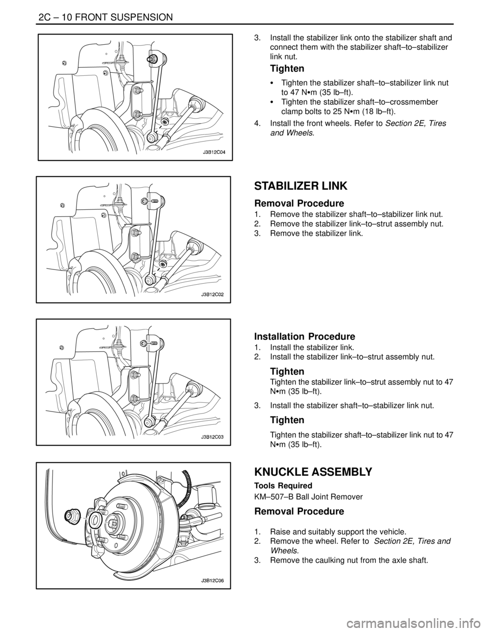
3. Install the stabilizer link onto the stabilizer shaft and
connect them with the stabilizer shaft–to–stabilizer
link nut.
Tighten
S Tighten the stabilizer shaft–to–stabilizer link nut
to 47 NSm (35 lb–ft).
S Tighten the stabilizer shaft–to–crossmember
clamp bolts to 25 NSm (18 lb–ft).
4. Install the front wheels. Refer to Section 2E, Tires
and Wheels.
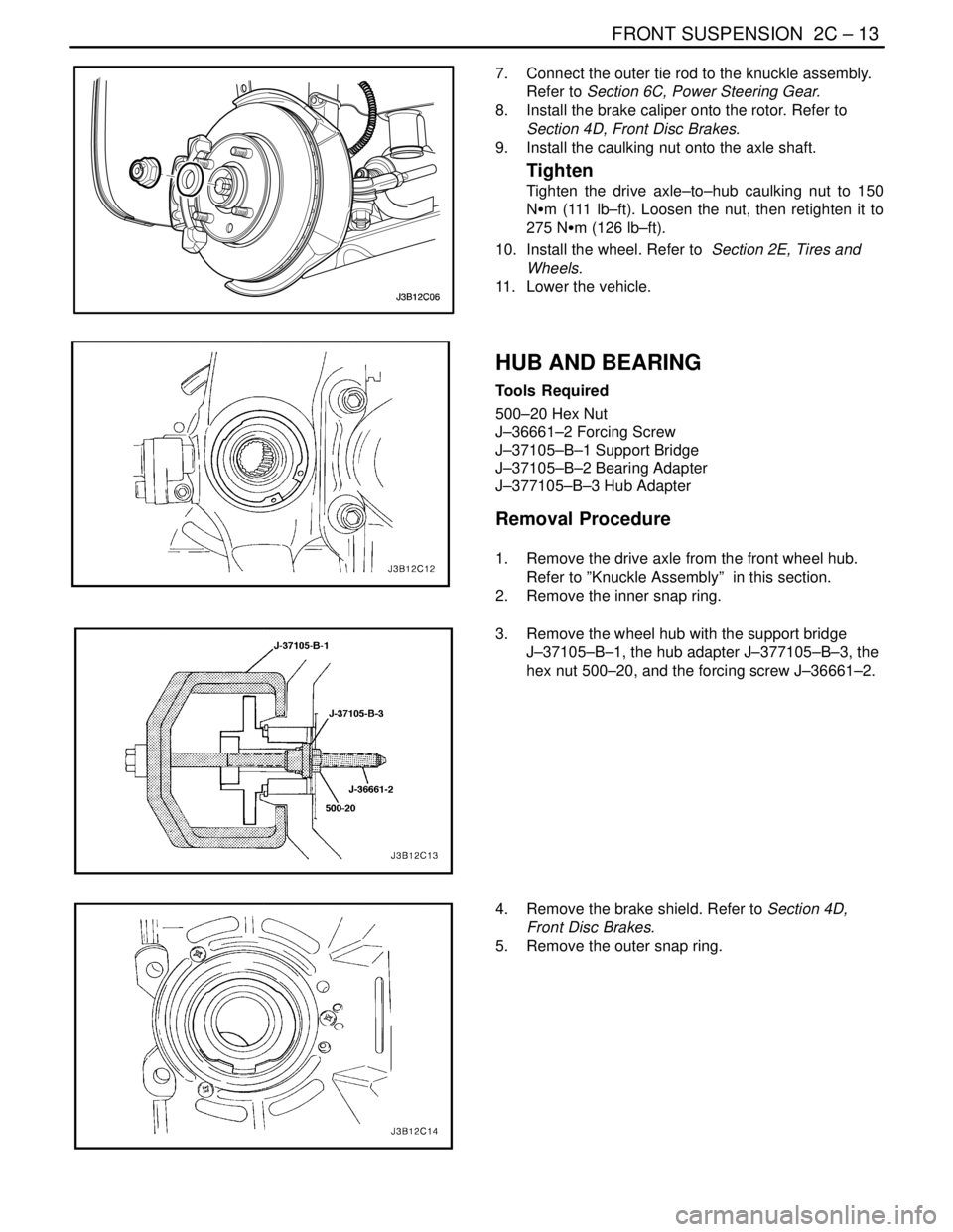
STABILIZER LINK
Removal Procedure
1. Remove the stabilizer shaft–to–stabilizer link nut.
2. Remove the stabilizer link–to–strut assembly nut.
3. Remove the stabilizer link.
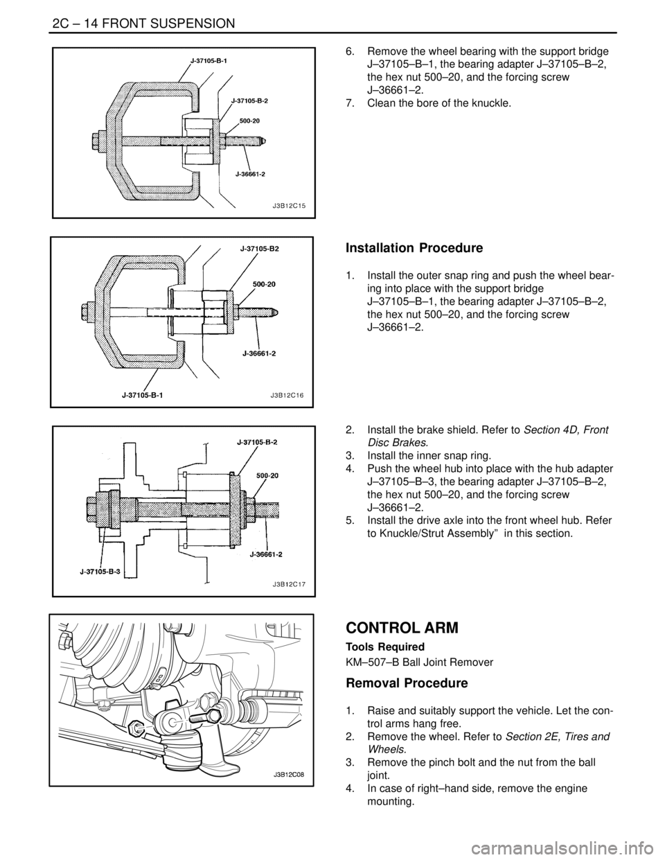
Installation Procedure
1. Install the stabilizer link.
2. Install the stabilizer link–to–strut assembly nut.
Tighten
Tighten the stabilizer link–to–strut assembly nut to 47
NSm (35 lb–ft).
3. Install the stabilizer shaft–to–stabilizer link nut.
Tighten
Tighten the stabilizer shaft–to–stabilizer link nut to 47
NSm (35 lb–ft).
KNUCKLE ASSEMBLY
Tools Required
KM–507–B Ball Joint Remover
Removal Procedure
1. Raise and suitably support the vehicle.
2. Remove the wheel. Refer to Section 2E, Tires and
Wheels.
3. Remove the caulking nut from the axle shaft.
Page 928 of 2643
FRONT SUSPENSION 2C – 11
DAEWOO V–121 BL4
4. Remove the brake caliper from the rotor. Support
the caliper so it does not hang from the hydraulic
brake hose. Refer to Section 4D, Front Disc
Brakes.
5. Remove the outer tie rod from the knuckle assem-
bly. Refer to Section 6C, Power Steering Gear.
6. On vehicles equipped with the antilock braking sys-
tem (ABS), disconnect the ABS speed sensor elec-
trical connection from the knuckle.
7. Remove the ball joint pinch bolt and the nut.
8. Separate the knuckle from the ball joint using the
ball joint remover KM–507–B.
9. Remove the nuts from the bolts that connect the
knuckle assembly to the strut assembly.
Page 930 of 2643

FRONT SUSPENSION 2C – 13
DAEWOO V–121 BL4
7. Connect the outer tie rod to the knuckle assembly.
Refer to Section 6C, Power Steering Gear.
8. Install the brake caliper onto the rotor. Refer to
Section 4D, Front Disc Brakes.
9. Install the caulking nut onto the axle shaft.
Tighten
Tighten the drive axle–to–hub caulking nut to 150
NSm (111 lb–ft). Loosen the nut, then retighten it to
275 NSm (126 lb–ft).
10. Install the wheel. Refer to Section 2E, Tires and
Wheels.
11. Lower the vehicle.
HUB AND BEARING
Tools Required
500–20 Hex Nut
J–36661–2 Forcing Screw
J–37105–B–1 Support Bridge
J–37105–B–2 Bearing Adapter
J–377105–B–3 Hub Adapter
Removal Procedure
1. Remove the drive axle from the front wheel hub.
Refer to ”Knuckle Assembly” in this section.
2. Remove the inner snap ring.
3. Remove the wheel hub with the support bridge
J–37105–B–1, the hub adapter J–377105–B–3, the
hex nut 500–20, and the forcing screw J–36661–2.
4. Remove the brake shield. Refer to Section 4D,
Front Disc Brakes.
5. Remove the outer snap ring.
Page 931 of 2643

2C – 14IFRONT SUSPENSION
DAEWOO V–121 BL4
6. Remove the wheel bearing with the support bridge
J–37105–B–1, the bearing adapter J–37105–B–2,
the hex nut 500–20, and the forcing screw
J–36661–2.
7. Clean the bore of the knuckle.
Installation Procedure
1. Install the outer snap ring and push the wheel bear-
ing into place with the support bridge
J–37105–B–1, the bearing adapter J–37105–B–2,
the hex nut 500–20, and the forcing screw
J–36661–2.
2. Install the brake shield. Refer to Section 4D, Front
Disc Brakes.
3. Install the inner snap ring.
4. Push the wheel hub into place with the hub adapter
J–37105–B–3, the bearing adapter J–37105–B–2,
the hex nut 500–20, and the forcing screw
J–36661–2.
5. Install the drive axle into the front wheel hub. Refer
to Knuckle/Strut Assembly” in this section.
CONTROL ARM
Tools Required
KM–507–B Ball Joint Remover
Removal Procedure
1. Raise and suitably support the vehicle. Let the con-
trol arms hang free.
2. Remove the wheel. Refer to Section 2E, Tires and
Wheels.
3. Remove the pinch bolt and the nut from the ball
joint.
4. In case of right–hand side, remove the engine
mounting.
Page 933 of 2643
2C – 16IFRONT SUSPENSION
DAEWOO V–121 BL4
5. Install the control arm–to–crossmember bolts.
Tighten
S Tighten the front control arm–to–crossmember
bolt to 125 NSm (92 lb–ft).
S Tighten the rear control arm–to–crossmember
bolt to 110 NSm (81 lb–ft).
6. Install the wheel. Refer to Section 2E, Tires and
Wheels.
7. Lower the vehicle.
STRUT ASSEMBLY
Removal Procedure
1. Remove the strut upper cap and nut.
2. Raise and suitably support the vehicle.
3. Remove the wheel. Refer to Section 2E, Tires and
Wheels.
4. On vehicles equipped with an antilock braking sys-
tem (ABS), disconnect the ABS sensor line from
the strut assembly.
5. Remove the brake line from the securing bracket
on the strut assembly.
6. Disconnect the stabilizer shaft link by removing the
stabilizer link–to–strut assembly nut.
Page 935 of 2643

2C – 18IFRONT SUSPENSION
DAEWOO V–121 BL4
3. Connect the stabilizer shaft link to the strut assem-
bly by attaching the stabilizer link–to–strut assem-
bly nut.
Tighten
Tighten the stabilizer link–to–strut assembly nut to 47
NSm (35 lb–ft).
4. Install the brake line to the securing bracket on the
strut assembly.
5. On vehicles equipped with the ABS, connect the
ABS sensor line to the strut assembly.
6. Install the wheel. Refer to Section 2E, Tires and
Wheels.
7. Lower the vehicle.
8. Install the nuts securing the strut assembly to the
body of the vehicle.
Tighten
Tighten the strut assembly–to–body nuts to 65 NSm
(48 lb–ft).
CROSSMEMBER ASSEMBLY
Removal Procedure
1. Raise and suitably support the vehicle.
2. Remove the wheels. Refer to Section 2E, Tires and
Wheels.
3. Remove the nuts and bolts from the steering gear
mounting bracket.
4. Remove the return line bolt from the clip on the
crossmember.
5. Remove the exhaust pipe forward of the catalytic
converter. Refer to Section 1G, Engine Exhaust.
6. Disconnect the tie rod from the knuckle assembly.
Refer to Section 6C, Power Steering Gear.
7. Disconnect the ball joint from the knuckle assembly.
Refer to ”Knuckle Assembly” in this section.
8. Disconnect the stabilizer link from the strut assem-
bly. Refer to ”Stabilizer Link” in this section.
9. Remove the crossmember link–to–transaxle brack-
et nut.
1) Remove the right lower engine mount.
2) Remove the rear transmission mount bracket.
Page 936 of 2643
FRONT SUSPENSION 2C – 19
DAEWOO V–121 BL4
10. Remove the rear crossmember–to–body bolts.
CAUTION : Two technicians must hold the front
crossmember assembly and suitably support the as-
sembly with a jack stand during removal of the front
attachment bolts. Failure to support the front cross-
member properly can result in personal injury.
11. Remove the front crossmember–to–body bolts.
12. Remove the crossmember assembly from the ve-
hicle.
Installation Procedure
1. Install the crossmember assembly.
2. Install the rear crossmember–to–body bolts.
Tighten
Tighten the rear crossmember–to–body bolts to 196
NSm (145 lb–ft).
3. Install the front crossmember–to–body bolts.
Tighten
Tighten the front crossmember–to–body bolts to 130
NSm (96 lb–ft).
4. Install the bolts and nuts on the steering gear
mounting brackets.
5. Install the return line bolt into the clip on the cross-
member. Refer to Section 6C, Power Steering
Gear.