2004 DAEWOO LACETTI steering
[x] Cancel search: steeringPage 2327 of 2643

9E – 28IINSTRUMENTATION/DRIVER INFORMATION
DAEWOO V–121 BL4
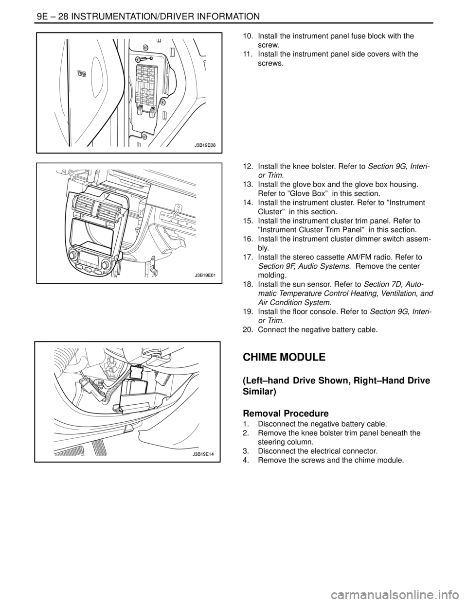
10. Install the instrument panel fuse block with the
screw.
11. Install the instrument panel side covers with the
screws.
12. Install the knee bolster. Refer to Section 9G, Interi-
or Trim.
13. Install the glove box and the glove box housing.
Refer to ”Glove Box” in this section.
14. Install the instrument cluster. Refer to ”Instrument
Cluster” in this section.
15. Install the instrument cluster trim panel. Refer to
”Instrument Cluster Trim Panel” in this section.
16. Install the instrument cluster dimmer switch assem-
bly.
17. Install the stereo cassette AM/FM radio. Refer to
Section 9F, Audio Systems. Remove the center
molding.
18. Install the sun sensor. Refer to Section 7D, Auto-
matic Temperature Control Heating, Ventilation, and
Air Condition System.
19. Install the floor console. Refer to Section 9G, Interi-
or Trim.
20. Connect the negative battery cable.
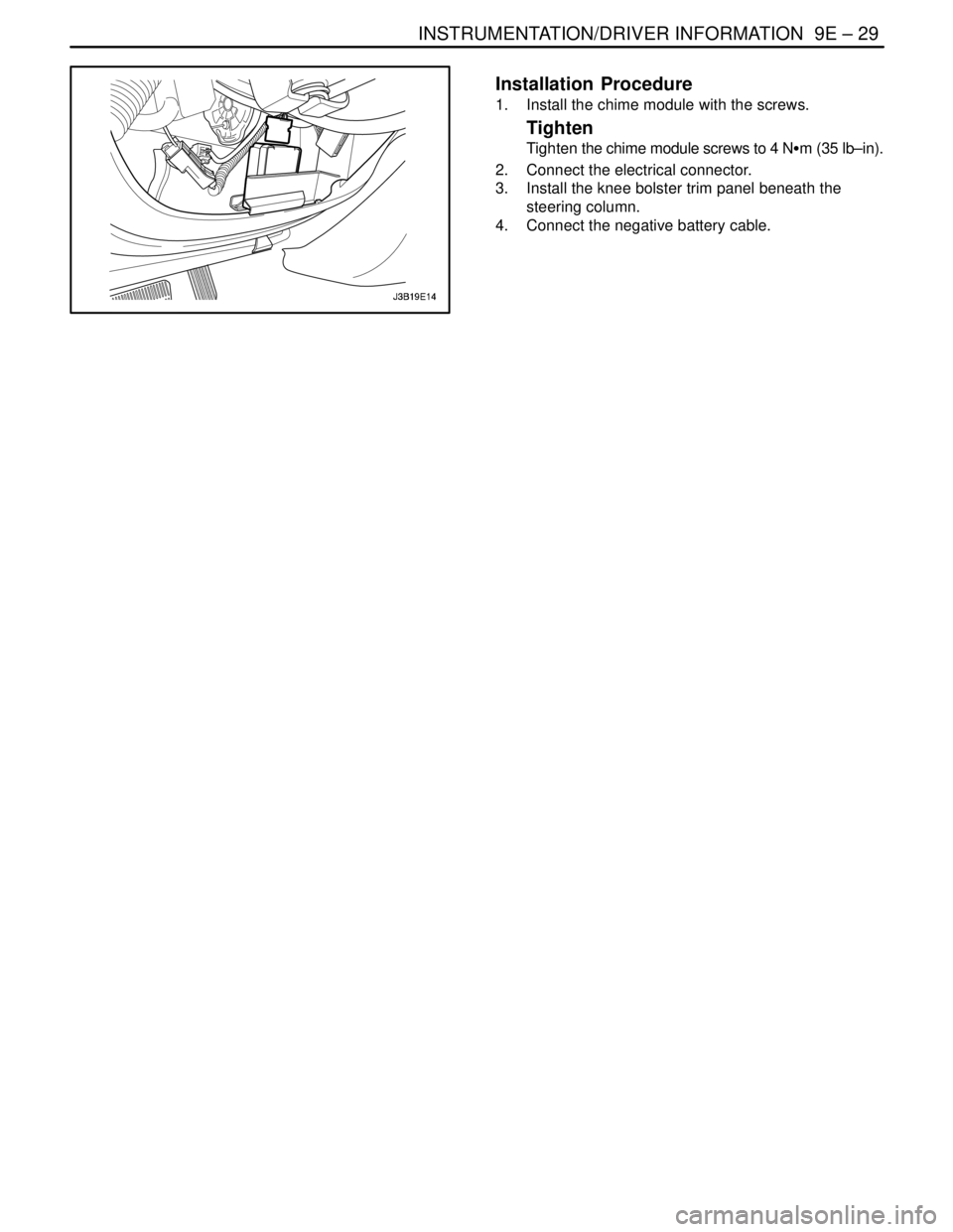
CHIME MODULE
(Left–hand Drive Shown, Right–Hand Drive
Similar)
Removal Procedure
1. Disconnect the negative battery cable.
2. Remove the knee bolster trim panel beneath the
steering column.
3. Disconnect the electrical connector.
4. Remove the screws and the chime module.
Page 2328 of 2643

INSTRUMENTATION/DRIVER INFORMATION 9E – 29
DAEWOO V–121 BL4
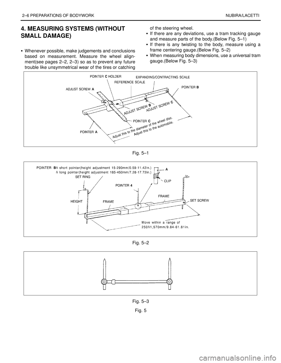
Installation Procedure
1. Install the chime module with the screws.
Tighten
Tighten the chime module screws to 4 NSm (35 lb–in).
2. Connect the electrical connector.
3. Install the knee bolster trim panel beneath the
steering column.
4. Connect the negative battery cable.
Page 2329 of 2643

9E – 30IINSTRUMENTATION/DRIVER INFORMATION
DAEWOO V–121 BL4
GENERAL DESCRIPTION
AND SYSTEM OPERATION
CIGAR LIGHTER
The cigar lighter is located in the front portion of the floor
console. To use the lighter, push it in completely. When the
lighter is hot, it will release itself from contact with the heat-
ing element. The lighter and the heating element can be
damaged if the lighter is not allowed to release itself fully
from the heating element.
ASHTRAY
The ashtray is located below the audio system. To access
the ashtray, pull it out from the center console. The ashtray
lamp will go on when the parking lamps or the headlamps
are turned on.
INSTRUMENT PANEL VENTS
The center and the side vents in the instrument panel can
be adjusted up and down and from side to side. The side
vents can also be aimed toward the side windows in order
to defog them.
GLOVE BOX
The glove box can be opened by pulling up on the latch
handle. The glove box must be removed in order to gain
access to the passenger’s side airbag module.
DIGTAL CLOCK
The digital clock is located in the instrument panel, above
the audio system. The clock is capable of a 12–hour or a
24–hour display.
INSTRUMENT CLUSTER
The instrument cluster is located above the steering col-
umn and in the instrument cluster trim panel. The instru-
ment cluster contains the instruments that provide the
driver with vehicle performance information. The instru-
ment cluster contains a speedometer, an odometer, a trip
odometer, a temperature gauge, a fuel gauge, and several
indicator lamps. For replacement of the indicator lamp
bulbs contained in the instrument cluster, refer to ”Instru-
ment Cluster Indicator Lamps Specifications” and”Instru-
ment Cluster Indicator Lamps” in this section.
SPEEDOMETER/ODOMETER/TRIP
ODOMETER
The speedometer measures the speed of the vehicle in
km/h (mph in some countries). It consists of an instrument
cluster gauge connected to the vehicle speed sensor
(VSS) on the transaxle output shaft.The odometer measures in kilometers (miles in some
countries) the total distance the vehicle has traveled since
it was manufactured. It consists of an instrument cluster
gauge connected to the VSS on the transaxle output shaft.
The trip odometer measures the distance the vehicle has
traveled since the odometer was last reset. It consists of
an instrument cluster gauge connected to the VSS on the
transaxle output shaft. The trip odometer can be reset to
zero at any time so that the driver can record the distance
traveled from any starting point.
FUEL GAUGE
The fuel gauge consists of an instrument cluster gauge
connected to a sending unit in the fuel tank.
The fuel gauge indicates the quantity of fuel in the tank
only when the ignition switch is turned to ON or ACC.
When the ignition is turned to LOCK or START, the pointer
may come to rest at any position.
TEMPERATURE GAUGE
The temperature gauge consists of an instrument cluster
gauge connected to a temperature sensor that is in con-
tact with the circulating engine coolant.
The temperature gauge indicates the temperature of the
coolant. Prolonged driving or idling in very hot weather
may cause the pointer to move beyond the center of the
gauge. The engine is overheating if the pointer moves into
the red zone at the upper limit of the gauge.
INSTRUMENT CLUSTER INDICATOR
LAMPS
The instrument cluster contains indicator lamps that indi-
cate the functioning of certain systems or the existence of
potential problems with the operation of the vehicle. The
indicator lamps are replaceable. For replacement of the in-
dicator lamps contained in the instrument cluster, refer to
”Instrument Cluster Indicator Lamps Specifications”
and”Instrument Cluster Indicator Lamps” in this section.
CHIME MODULE
The chime module is located above the instrument panel
fuse block and will sound in order to bring attention to one
or more of the following conditions:
S The lamps are on, the door is ajar, and the ignition
switch is not in ACC, ON, or START.
S The seat belt is unbuckled when the ignition switch
is in ON or START.
S The door is open when the ignition switch is in ON
or START.
S The key is left in the ignition switch when the igni-
tion is in LOCK and the door is open.
Page 2409 of 2643

9N – 6IFRAME AND UNDERBODY
DAEWOO V–121 BL4
MAINTENANCE AND REPAIR
ON–VEHICLE SERVICE
ALIGNMENT CHECKING
An accurate method of determining the alignment of the
underbody uses a measuring tram gauge. The tram gauge
set used to perform the recommended measuring checks
must include a vertical pointer able to reach 457 mm (18
inches).
Two types of measurements can be made with a tram
gauge: direct point–to–point measurements and mea-
surements calculated on a horizontal plane (datum line)
parallel to the underbody. Point–to–point measurements
are generally taken on steering and suspension engine
compartment parts and simply require the vertical pointers
to be set equally.
For horizontal plane measurements, the vertical pointers
must be set as specified for each point to be measured.
Dimensions–to–gauge holes are measured to the center
of the holes and flush to the adjacent surface metal unless
otherwise specified. It is recommended that the diagonal
dimensions to the cross–body be checked on both sides
in order to verify the dimensional accuracy of the vehicle
underbody.
FLOOR PAN INSULATORS
The floor pan insulators have been designed for the higher
floor pan temperatures that result from the use of the cata-
lytic converter in the exhaust system. Therefore, when
servicing a vehicle, it is essential that any insulators that
may have been disturbed or removed be reinstalled in the
original sequence and location. Also, if an insulator needs
to be replaced, use only the insulation specified for that
location on the floor pan.
When servicing or replacing interior insulators, observe
the following instructions.
S Install the insulators in the original position and se-
quence. Butt the pieces together in order to avoid
gapping or overlapping.
S If it is necessary to replace an insulator, use only
the specified insulation.
S Use the original part to determine the amount of
replacement material required and as a template for
cutting and fitting the new piece to the floor pan.
S When installing the insulator, do not enlarge any
cutouts or holes that are used for the attachment of
interior parts such as the instrument panel or the
floor console.
S Route the cross–body harness for interior parts
over the floor pan insulators. Clip it in the original
location.
S Do not apply spray–on deadeners or trim adhesives
to the top of the floor pan at the area directly over
the catalytic converter or the muffler.
Page 2524 of 2643

2–4 PREPARATIONS OF BODYWORK NUBIRA/LACETTI
2. CHECKPOINTS
S Accurate Inspection of Damaged Parts(Visual)
.
Seat Belts
Always replace the seat belt if :
1. The belt material is cut, punctured, burned or in any
way damaged.
2. The buckle or retractor does not work properly.
3. They were being worn at the time of a collision(also
check for damage at the seat belt anchor points).
4. Their condition is questionable.
.
Front Section :
1. Is there any bending, splitting, denting or other dam-
age to the suspension and its related parts?
2. Is there any deformation of the front panel or radiator
crossmember? Have any of the connected sections
come apart?
3. Are there any creases or distortion in the front wheel-
house or side frame? Have any of the connected sec-
tions come apart?
4. Is there any bending or twisting of the whole front
area?
5. Is there any deformation like creases, bulges, or dents
in the front pillar, dash panel, floor, etc.?
6. Is there any vertical twisting or misaligned clearance
in the door?
7. Is the windshield seal broken?
8. Is there any deformation in the vicinity of the top part
of the roof panel’s center pillar?
9. Is there any damage inside the automobile(is there
any twisting of the dash panel, or anything irregular with
the clearances or sheet–mounting parts)?
10. Is there any damage to the steering wheel? Is there
any deformation in the column and the column–mounted
parts?
11. Is there any oil or water leakage and damage to the en-
gine, transmission or brakes?
12. Is there any irregular noise in the gear changing opera-
tion, engine and transmission rotation?
13. Are there any traces of contact between the engine
block and the center crossmember ?
14. Is there any damage to brake or fuel lines, or wire har-
nesses?Rear Section :
1. Is there any twisting, bulging or denting of the rear floor
any rear bolsters? Have any of the connected sections
come apart?
2. Is there any irregular bulging or denting in the rear
fender?
3. Is there any distortion in the rear inner panel? Is there
any bending and denting in the vicinity of the rear pillar?
4. Is there any distortion or creasing is the rear wheel-
house and arch sections? Have any of the connected
sections come apart?
5. Is there anything irregular in the rear glass seal clear-
ance?
6. Is there any twisting or misalignment of the clearance
of the trunk lid opening section?
7. Is there any bending, splitting, denting or other dam-
age to the suspension and its related parts?
8. Is there any deformation of the rear floor crossmem-
ber, trunk floor panel and back panel? Have any of the
connected sections come apart?
.
Impact Beam :
Always replace the door assembly if :
1. The external force makes the impact beam of door in-
ner deform.
Always replace impact beam if :
2. The external force makes the impact beam of front
bumper and rear bumper deform.
Page 2526 of 2643

2–6 PREPARATIONS OF BODYWORK NUBIRA/LACETTI
4. MEASURING SYSTEMS (WITHOUT
SMALL DAMAGE)
S Whenever possible, make judgements and conclusions
based on measurement. Measure the wheel align-
ment(see pages 2–2, 2–3) so as to prevent any future
trouble like unsymmetrical wear of the tires or catchingof the steering wheel.
S If there are any deviations, use a tram tracking gauge
and measure parts of the body.(Below Fig. 5–1)
S If there is any twisting to the body, measure using a
frame centering gauge.(Below Fig. 5–2)
S When measuring body dimensions, use a universal tram
gauge.(Below Fig. 5–3)
.
Fig. 5–1
Fig. 5–2
Fig. 5–3
Fig. 5