2004 DAEWOO LACETTI width
[x] Cancel search: widthPage 123 of 2643

1.8L DOHC ENGINE MECHANICAL 1C2 – 3
DAEWOO V–121 BL4
Application Description
Diameter (All)
Out of Round (Maximum)48.970~ 48.988 mm (1.9279~1.9287 in.)
0.004 mm (0.00015 in.)
Cylinder Head:
Valve Stem Protrusion39.2~39.8 mm (1.54~1.56 in.)
Valve Guide Height13.7~14.0 mm (0.54~0.57 in.)
Overall Height134 ± 0.025 mm (5.2755~0.0009 in.)
Minimum Overall Height After Machining133.9 mm (5.27 in.)
Valve System:
Valve Lash CompensatorsHydraulic Tappet
Seat Runout (Maximum, All)0.03 mm (0.00118 in.)
Face Runout (Maximum, All)0.03 mm (0.00118 in.)
Valve Stem Diameter:
Intake
Exhaust5.945~5.960 mm (0.2341~0.2346 in.)
5.945~5.960 mm (0.2341~0.2346 in.)
Valve Diameter:
Intake
Exhaust32 ± 0.1 mm (1.2598 ± 0.0039 in.)
29 ± 0.1 mm (1.1417 ± 0.0039 in.)
Valve Seat Width:
Intake
Exhaust1.0~1.5 mm (0.039~0.059 in.)
1.7~2.2 mm (0.066~0.086 in.)
Valve Face Angle44°
Valve Guide Inside Diameter7.03~7.05 mm (0.276~0.277 in.)
Oil Pump:
Gear Lash0.10~0.20 mm (0.003~0.007 in.)
Outer Gear to Body0.11~0.19 mm (0.004~0.007 in.)
Outer Gear to Crescent0.40~0.50 mm (0.015~0.019 in.)
Inner Gear to Crescent0.35~0.40 mm (0.013~0.015 in.)
End Clearance0.030~0.10 mm (0.001~0.003 in.)
Sealants and Adhesives:
Rear Main Bearing CapGE p/n RTV 159
Camshaft Carrier to Cylinder HeadHN 1581 (Loctite® 515)
Oil Pan BoltsHN 1256 (Loctite® 242)
Oil Pump BoltsHN 1256 (Loctite® 242)
Oil Pan Pickup Tube BoltsHN 1256 (Loctite® 242)
Oil Gallery PlugHN 1256 (Loctite® 242)
Coolant Jacket Caps and Plugs (Freeze Plugs)HN 1756 (Loctite® 176)
Exhaust Manifold Studs/NutsAnti–seize Compound (HMC Spec HN1325)
Page 178 of 2643
1C2 – 58I1.8L DOHC ENGINE MECHANICAL
DAEWOO V–121 BL4
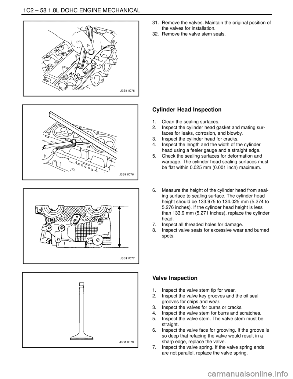
31. Remove the valves. Maintain the original position of
the valves for installation.
32. Remove the valve stem seals.
Cylinder Head Inspection
1. Clean the sealing surfaces.
2. Inspect the cylinder head gasket and mating sur-
faces for leaks, corrosion, and blowby.
3. Inspect the cylinder head for cracks.
4. Inspect the length and the width of the cylinder
head using a feeler gauge and a straight edge.
5. Check the sealing surfaces for deformation and
warpage. The cylinder head sealing surfaces must
be flat within 0.025 mm (0.001 inch) maximum.
6. Measure the height of the cylinder head from seal-
ing surface to sealing surface. The cylinder head
height should be 133.975 to 134.025 mm (5.274 to
5.276 inches). If the cylinder head height is less
than 133.9 mm (5.271 inches), replace the cylinder
head.
7. Inspect all threaded holes for damage.
8. Inspect valve seats for excessive wear and burned
spots.
Valve Inspection
1. Inspect the valve stem tip for wear.
2. Inspect the valve key grooves and the oil seal
grooves for chips and wear.
3. Inspect the valves for burns or cracks.
4. Inspect the valve stem for burrs and scratches.
5. Inspect the valve stem. The valve stem must be
straight.
6. Inspect the valve face for grooving. If the groove is
so deep that refacing the valve would result in a
sharp edge, replace the valve.
7. Inspect the valve spring. If the valve spring ends
are not parallel, replace the valve spring.
Page 181 of 2643
1.8L DOHC ENGINE MECHANICAL 1C2 – 61
DAEWOO V–121 BL4
4. Inspect the dimension for the valve seat width.
S Intake: 1.2 to 1.4 mm (0.047 to 0.055 inch).
S Exhaust: 1.4 to 1.8 mm (0.055 to 0.070 inch).
5. Inspect the assembly height of the intake valves
and the exhaust valves. If the dimension is exceed-
ed, install new valves. Inspect the assembly height
of the intake valves and the exhaust valves again. If
the valve assembly height is still too large despite
replacing the valves, replace the cylinder head.
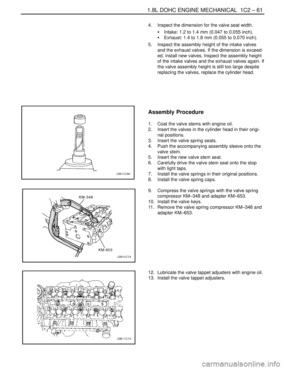
Assembly Procedure
1. Coat the valve stems with engine oil.
2. Insert the valves in the cylinder head in their origi-
nal positions.
3. Insert the valve spring seats.
4. Push the accompanying assembly sleeve onto the
valve stem.
5. Insert the new valve stem seat.
6. Carefully drive the valve stem seal onto the stop
with light taps.
7. Install the valve springs in their original positions.
8. Install the valve spring caps.
9. Compress the valve springs with the valve spring
compressor KM–348 and adapter KM–653.
10. Install the valve keys.
11. Remove the valve spring compressor KM–348 and
adapter KM–653.
12. Lubricate the valve tappet adjusters with engine oil.
13. Install the valve tappet adjusters.
Page 187 of 2643
1.8L DOHC ENGINE MECHANICAL 1C2 – 67
DAEWOO V–121 BL4
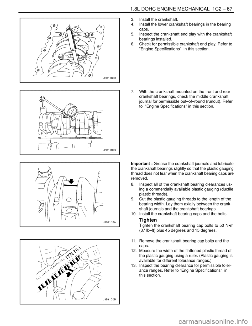
3. Install the crankshaft.
4. Install the lower crankshaft bearings in the bearing
caps.
5. Inspect the crankshaft end play with the crankshaft
bearings installed.
6. Check for permissible crankshaft end play. Refer to
”Engine Specifications” in this section.
7. With the crankshaft mounted on the front and rear
crankshaft bearings, check the middle crankshaft
journal for permissible out–of–round (runout). Refer
to ”Engine Specifications” in this section.
Important : Grease the crankshaft journals and lubricate
the crankshaft bearings slightly so that the plastic gauging
thread does not tear when the crankshaft bearing caps are
removed.
8. Inspect all of the crankshaft bearing clearances us-
ing a commercially available plastic gauging (ductile
plastic threads).
9. Cut the plastic gauging threads to the length of the
bearing width. Lay them axially between the crank-
shaft journals and the crankshaft bearings.
10. Install the crankshaft bearing caps and the bolts.
Tighten
Tighten the crankshaft bearing cap bolts to 50 NSm
(37 lb–ft) plus 45 degrees and 15 degrees.
11. Remove the crankshaft bearing cap bolts and the
caps.
12. Measure the width of the flattened plastic thread of
the plastic gauging using a ruler. (Plastic gauging is
available for different tolerance ranges.)
13. Inspect the bearing clearance for permissible toler-
ance ranges. Refer to ”Engine Specifications” in
this section.
Page 188 of 2643
1C2 – 68I1.8L DOHC ENGINE MECHANICAL
DAEWOO V–121 BL4
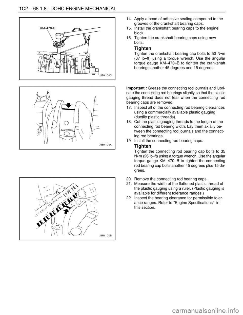
14. Apply a bead of adhesive sealing compound to the
grooves of the crankshaft bearing caps.
15. Install the crankshaft bearing caps to the engine
block.
16. Tighten the crankshaft bearing caps using new
bolts.
Tighten
Tighten the crankshaft bearing cap bolts to 50 NSm
(37 lb–ft) using a torque wrench. Use the angular
torque gauge KM–470–B to tighten the crankshaft
bearings another 45 degrees and 15 degrees.
Important : Grease the connecting rod journals and lubri-
cate the connecting rod bearings slightly so that the plastic
gauging thread does not tear when the connecting rod
bearing caps are removed.
17. Inspect all of the connecting rod bearing clearances
using a commercially available plastic gauging
(ductile plastic threads).
18. Cut the plastic gauging threads to the length of the
connecting rod bearing width. Lay them axially be-
tween the connecting rod journals and the connect-
ing rod bearings.
19. Install the connecting rod bearing caps.
Tighten
Tighten the connecting rod bearing cap bolts to 35
NSm (26 lb–ft) using a torque wrench. Use the angular
torque gauge KM–470–B to tighten the connecting
rod bearing cap bolts another 45 degrees plus 15 de-
grees.
20. Remove the connecting rod bearing caps.
21. Measure the width of the flattened plastic thread of
the plastic gauging using a ruler. (Plastic gauging is
available for different tolerance ranges.)
22. Inspect the bearing clearance for permissible toler-
ance ranges. Refer to ”Engine Specifications” in
this section.
Page 193 of 2643
1.8L DOHC ENGINE MECHANICAL 1C2 – 73
DAEWOO V–121 BL4
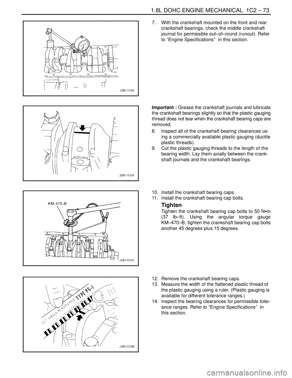
7. With the crankshaft mounted on the front and rear
crankshaft bearings, check the middle crankshaft
journal for permissible out–of–round (runout). Refer
to ”Engine Specifications” in this section.
Important : Grease the crankshaft journals and lubricate
the crankshaft bearings slightly so that the plastic gauging
thread does not tear when the crankshaft bearing caps are
removed.
8. Inspect all of the crankshaft bearing clearances us-
ing a commercially available plastic gauging (ductile
plastic threads).
9. Cut the plastic gauging threads to the length of the
bearing width. Lay them axially between the crank-
shaft journals and the crankshaft bearings.
10. Install the crankshaft bearing caps.
11. Install the crankshaft bearing cap bolts.
Tighten
Tighten the crankshaft bearing cap bolts to 50 NSm
(37 lb–ft). Using the angular torque gauge
KM–470–B, tighten the crankshaft bearing cap bolts
another 45 degrees plus 15 degrees.
12. Remove the crankshaft bearing caps.
13. Measure the width of the flattened plastic thread of
the plastic gauging using a ruler. (Plastic gauging is
available for different tolerance ranges.)
14. Inspect the bearing clearances for permissible toler-
ance ranges. Refer to ”Engine Specifications” in
this section.
Page 194 of 2643
1C2 – 74I1.8L DOHC ENGINE MECHANICAL
DAEWOO V–121 BL4
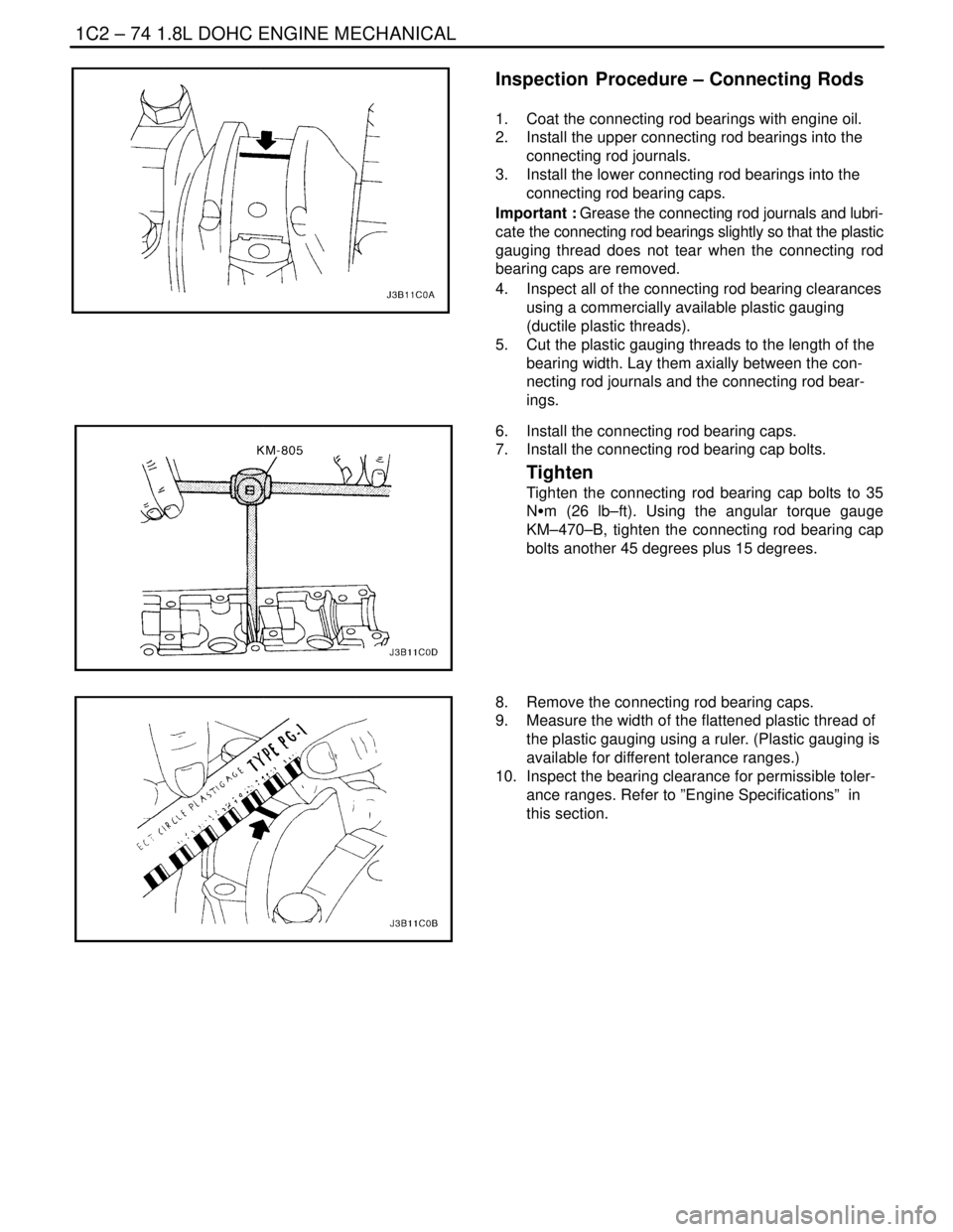
Inspection Procedure – Connecting Rods
1. Coat the connecting rod bearings with engine oil.
2. Install the upper connecting rod bearings into the
connecting rod journals.
3. Install the lower connecting rod bearings into the
connecting rod bearing caps.
Important : Grease the connecting rod journals and lubri-
cate the connecting rod bearings slightly so that the plastic
gauging thread does not tear when the connecting rod
bearing caps are removed.
4. Inspect all of the connecting rod bearing clearances
using a commercially available plastic gauging
(ductile plastic threads).
5. Cut the plastic gauging threads to the length of the
bearing width. Lay them axially between the con-
necting rod journals and the connecting rod bear-
ings.
6. Install the connecting rod bearing caps.
7. Install the connecting rod bearing cap bolts.
Tighten
Tighten the connecting rod bearing cap bolts to 35
NSm (26 lb–ft). Using the angular torque gauge
KM–470–B, tighten the connecting rod bearing cap
bolts another 45 degrees plus 15 degrees.
8. Remove the connecting rod bearing caps.
9. Measure the width of the flattened plastic thread of
the plastic gauging using a ruler. (Plastic gauging is
available for different tolerance ranges.)
10. Inspect the bearing clearance for permissible toler-
ance ranges. Refer to ”Engine Specifications” in
this section.
Page 253 of 2643

ENGINE CONTROLS 1F – 7
DAEWOO V–121 BL4
Parameter ValueScaling
A/C RequestYes/NoNo
A/C ClutchOn/OffOff
Fuel Pump CommandOn/OffOn
Closed LoopYes/NoYe s
Throttle At IdleYes/NoNo
O2 Ready (B1–S1)Yes/NoYe s
Knock PresentYes/NoNo
Fan LowOn/OffOn/Off
Fan HighOn/OffOn/Off
TCC Engaged (Only AT)Yes/NoYe s
Park/Neutral (Only AT)P/N and R/N/DP/N
Fuel Level InputVvaries
Fuel Level Output%varies
Fuel Trim Cell–18
G–SensorV1.1 – 3.7 V (Non–ABS Only)
Engine RuntimeHH:MM:SSHours:Minutes:Seconds
* Condition: Warmed up, idle, park or neutral, A/C off
ENGINE DATA DISPLAY TABLE
DEFINITIONS
ECM Data Description
The following information will assist in diagnosing emis-
sion or driveability problems. A first technician can view
the displays while the vehicle is being driven by second
technician. Refer to Powertrain On–Board Diagnostic
(EOBD) System Check for addition information.
A/C Clutch
The A/C Relay represents the commanded state of the
A/C clutch control relay. The A/C clutch should be en-
gaged when the scan tool displays ON.
A/C Pressure
The A/C High Side displays the pressure value of the A/C
refrigerant pressure sensor. The A/C High Side helps to
diagnose the diagnostic trouble code (DTC) P0533.
A/C Request
The A/C Request represents whether the air conditioning
is being requested from the HVAC selector. The input is re-
ceived by the instrument panel cluster and then sent serial
data to the ECM and finally to the scan tool over KWP 2000
serial data.
Air Fuel Ratio
The Air Fuel Ration indicates the air to fuel ratio based on
the Front Heated Oxygen Sensor (HO2S1) inputs. The
ECM uses the fuel trims to adjust fueling in order to at-
tempt to maintain an air fuel ratio of 14.7:1.BARO
The Barometric Pressure (BARO) sensor measures the
change in the intake manifold pressure which results from
altitude changes. This value is updated at ignition ON and
also at Wide Open Throttle (WOT).
Base Injection PWM
Indicates the base Pulse Width Modulation (PWM) or ON
time of the indicated cylinder injector in milliseconds.
When the engine load is increased, the injector pulse width
will increase.
Calculated Air Flow
The calculated air flow is a calculation based on manifold
absolute pressure. The calculation is used in several diag-
nostics to determine when to run the diagnostics.
Desired Idle Speed
The ECM commands the idle speed. The ECM compen-
sates for various engine loads in order to maintain the de-
sired idle speed. The actual engine speed should remain
close to the desired idle under the various engine loads
with the engine idling.
Engine Coolant Temperature
The Engine Coolant Temperature (ECT) sensor sends en-
gine temperature information to the ECM. The ECM sup-
plies 5 volts to the engine coolant temperature sensor cir-
cuit. The sensor is a thermistor which changes internal
resistance as temperature changes. When the sensor is
cold (internal resistance high), the ECM monitors a high
voltage which it interprets as a cold engine. As the sensor
warms (internal resistance decreases), the voltage signal
will decrease and the ECM will interpret the lower voltage
as a warm engine.