2004 DAEWOO LACETTI radiator
[x] Cancel search: radiatorPage 141 of 2643

1.8L DOHC ENGINE MECHANICAL 1C2 – 21
DAEWOO V–121 BL4
39. Install the timing belt.
40. Check and adjust the timing belt tension. Refer to
”Timing Belt Check and Adjust” in this section.
41. Install the front timing belt cover.
42. Install the front timing belt cover bolts.
Tighten
Tighten the front timing belt cover bolts to 6 NSm (53
lb–in).
43. Install the crankshaft pulley.
44. Install the crankshaft pulley bolts.
Tighten
Tighten the crankshaft pulley bolts to 12 NSm (106 lb–
in).
45. Install the right engine mount bracket and retaining
bolts.
Tighten
Tighten the engine mount bracket retaining bolts to 55
NSm (41 lb–ft).
46. Remove the engine assembly lift support
J–28467–B.
47. Install the serpentine accessory drive belt. Refer to
Section 6B, Power Steering Pump.
48. Connect the upper radiator hose to the thermostat
housing.
49. Install the right front wheel well splash shield.
50. Install the right front wheel. Refer to Section 2E,
Tires and Wheels.
51. Install the air cleaner housing.
52. Install the air cleaner housing bolts.
Tighten
Tighten the air cleaner housing bolts to 10 NSm (89 lb–
in).
53. Connect the air cleaner outlet hose to the throttle
body.
54. Connect the breather tube to the camshaft cover.
55. Connect the MAT sensor connector.
Page 166 of 2643

1C2 – 46I1.8L DOHC ENGINE MECHANICAL
DAEWOO V–121 BL4
7. Install the timing belt automatic tensioner and bolt.
8. Install the camshaft gears. Refer to ”Camshaft
Gears” in this section.
9. Install the timing belt and timing belt cover. Refer to
”Timing Belt” in this section.
10. Connect the negative battery cable.
ENGINE
Removal Procedure
1. Remove the fuel pump fuse.
2. Start the engine. After it stalls, crank the engine for
10 seconds to rid the fuel system of fuel pressure.
3. Remove the hood. Refer to Section 9R, Body Front
End.
4. Drain the engine oil.
5. Disconnect the negative battery cable.
6. Discharge the air conditioning (A/C) system, if
equipped. Refer to Section 7B, Manual Control
Heating, Ventilation, and Air Conditioning Systems.
7. Disconnect the manifold air temperature (MAT)
sensor connector.
8. Remove the air cleaner outlet hose from the throttle
body and air cleaner housing.
9. Disconnect the breather tubes from the camshaft
cover.
10. Remove the right front wheel. Refer to Section 2E,
Tires and Wheels.
11. Remove the right front wheel well splash shield.
Refer to Section 9R, Body Font End.
12. Remove the serpentine accessory drive belt. Refer
to Section 6B, Power Steering Pump.
13. Drain the engine coolant. Refer to Section 1D, En-
gine Cooling.
14. Remove the cooling system radiator and the engine
cooling fans. Refer to Section 1D, Engine Cooling.
15. Disconnect the upper radiator hose from the ther-
mostat housing.
16. Disconnect the power steering return hose from the
power steering pump.
17. Disconnect the power steering pressure hose from
the power steering pump.
18. Disconnect the electrical connector at the direct
ignition system (DIS) coil and the electronic control
module (ECM) ground terminal and at the starter
motor.
Page 167 of 2643

1.8L DOHC ENGINE MECHANICAL 1C2 – 47
DAEWOO V–121 BL4
19. Disconnect the oxygen (O2) sensor connector, if
equipped.
20. Disconnect the idle air control (IAC) valve connec-
tor.
21. Disconnect the throttle position sensor (TPS) con-
nector.
22. Disconnect the engine coolant temperature sensor
(CTS) connector.
23. Disconnect the CTS connector.
24. Disconnect the generator voltage regulator connec-
tor and power lead.
25. Disconnect all of the necessary vacuum lines, in-
cluding the brake booster vacuum hose.
26. Disconnect the fuel return line at the fuel rail.
27. Disconnect the fuel feed line at the fuel rail.
28. Remove the fuel rail and injector channel cover as
an assembly. Refer to Section 1F, Engine Controls.
29. Disconnect the throttle cable from the throttle body
and the intake manifold bracket.
30. Disconnect the coolant hose at the throttle body.
31. Disconnect the heater outlet hose at the coolant
pipe.
32. Disconnect the coolant bypass hose from the cylin-
der head.
33. Disconnect the surge tank coolant hose from the
coolant pipe.
34. Disconnect the lower radiator hose from the coolant
pipe.
35. Disconnect the starter solenoid ”S” terminal wire
and power lead.
36. Remove the A/C compressor. Refer to Section 7B,
Manual Control Heating, Ventilation, and Air Condi-
tioning Systems.
37. Remove the exhaust flex pipe retaining nuts from
the exhaust manifold studs.
38. Remove the exhaust flex pipe retaining nuts from
the catalytic converter or the connecting pipe.
39. Remove the exhaust flex pipe.
Page 170 of 2643
1C2 – 50I1.8L DOHC ENGINE MECHANICAL
DAEWOO V–121 BL4
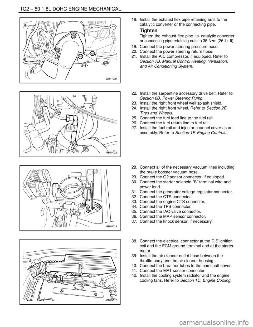
18. Install the exhaust flex pipe retaining nuts to the
catalytic converter or the connecting pipe.
Tighten
Tighten the exhaust flex pipe–to–catalytic converter
or connecting pipe retaining nuts to 35 NSm (26 lb–ft).
19. Connect the power steering pressure hose.
20. Connect the power steering return hose.
21. Install the A/C compressor, if equipped. Refer to
Section 7B, Manual Control Heating, Ventilation,
and Air Conditioning System.
22. Install the serpentine accessory drive belt. Refer to
Section 6B, Power Steering Pump.
23. Install the right front wheel well splash shield.
24. Install the right front wheel. Refer to Section 2E,
Tires and Wheels.
25. Connect the fuel feed line to the fuel rail.
26. Connect the fuel return line to fuel rail.
27. Install the fuel rail and injector channel cover as an
assembly. Refer to Section 1F, Engine Controls.
28. Connect all of the necessary vacuum lines including
the brake booster vacuum hose.
29. Connect the O2 sensor connector, if equipped.
30. Connect the starter solenoid ”S” terminal wire and
power lead.
31. Connect the generator voltage regulator connector.
32. Connect the CTS connector.
33. Connect the engine CTS connector.
34. Connect the TPS connector.
35. Connect the IAC valve connector.
36. Connect the MAP sensor connector.
37. Connect the knock sensor, if necessary
38. Connect the electrical connector at the DIS ignition
coil and the ECM ground terminal and at the starter
motor.
39. Install the air cleaner outlet hose between the
throttle body and the air cleaner housing.
40. Connect the breather tubes to the camshaft cover.
41. Connect the MAT sensor connector.
42. Install the cooling system radiator and the engine
cooling fans. Refer to Section 1D, Engine Cooling.
Page 171 of 2643
1.8L DOHC ENGINE MECHANICAL 1C2 – 51
DAEWOO V–121 BL4
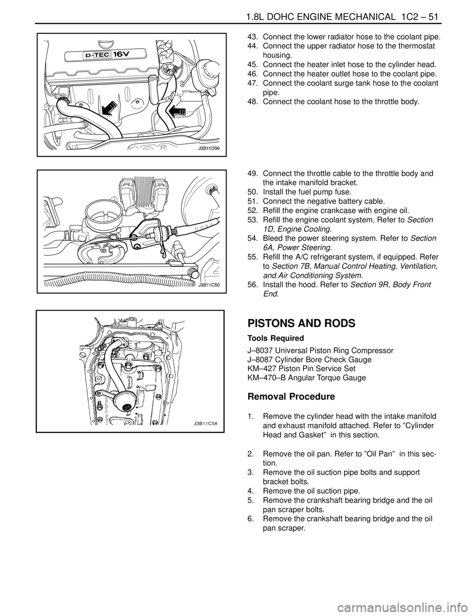
43. Connect the lower radiator hose to the coolant pipe.
44. Connect the upper radiator hose to the thermostat
housing.
45. Connect the heater inlet hose to the cylinder head.
46. Connect the heater outlet hose to the coolant pipe.
47. Connect the coolant surge tank hose to the coolant
pipe.
48. Connect the coolant hose to the throttle body.
49. Connect the throttle cable to the throttle body and
the intake manifold bracket.
50. Install the fuel pump fuse.
51. Connect the negative battery cable.
52. Refill the engine crankcase with engine oil.
53. Refill the engine coolant system. Refer to Section
1D, Engine Cooling.
54. Bleed the power steering system. Refer to Section
6A, Power Steering.
55. Refill the A/C refrigerant system, if equipped. Refer
to Section 7B, Manual Control Heating, Ventilation,
and Air Conditioning System.
56. Install the hood. Refer to Section 9R, Body Front
End.
PISTONS AND RODS
Tools Required
J–8037 Universal Piston Ring Compressor
J–8087 Cylinder Bore Check Gauge
KM–427 Piston Pin Service Set
KM–470–B Angular Torque Gauge
Removal Procedure
1. Remove the cylinder head with the intake manifold
and exhaust manifold attached. Refer to ”Cylinder
Head and Gasket” in this section.
2. Remove the oil pan. Refer to ”Oil Pan” in this sec-
tion.
3. Remove the oil suction pipe bolts and support
bracket bolts.
4. Remove the oil suction pipe.
5. Remove the crankshaft bearing bridge and the oil
pan scraper bolts.
6. Remove the crankshaft bearing bridge and the oil
pan scraper.
Page 196 of 2643

SECTION : 1D
ENGINE COOLING
CAUTION : Disconnect the negative battery cable before removing or installing any electrical unit or when a tool
or equipment could easily come in contact with exposed electrical terminals. Disconnecting this cable will help
prevent personal injury and damage to the vehicle. The ignition must also be in LOCK unless otherwise noted.
TABLE OF CONTENTS
SPECIFICATIONS1D–2 . . . . . . . . . . . . . . . . . . . . . . . . . .
Capacity 1D–2. . . . . . . . . . . . . . . . . . . . . . . . . . . . . . . . . .
Fastener Tightening Specifications 1D–2. . . . . . . . . . .
SPECIAL TOOLS1D–2 . . . . . . . . . . . . . . . . . . . . . . . . . . .
Special Tools Table 1D–2. . . . . . . . . . . . . . . . . . . . . . . .
DIAGNOSIS1D–3 . . . . . . . . . . . . . . . . . . . . . . . . . . . . . . . .
Thermostat Test 1D–3. . . . . . . . . . . . . . . . . . . . . . . . . . .
Surge Tank Cap Test 1D–3. . . . . . . . . . . . . . . . . . . . . . .
Cooling System Diagnosis 1D–4. . . . . . . . . . . . . . . . . .
COMPONENT LOCATOR1D–5 . . . . . . . . . . . . . . . . . . . .
Radiator/Fan 1D–5. . . . . . . . . . . . . . . . . . . . . . . . . . . . . .
Water Pump/Thermostat (1.4L/1.6L DOHC) 1D–6. . .
Water Pump/Thermostat (1.8L DOHC) 1D–7. . . . . . .
MAINTENANCE AND REPAIR1D–8 . . . . . . . . . . . . . . .
ON–VEHICLE SERVICE 1D–8. . . . . . . . . . . . . . . . . . . . . Draining and Refilling the Cooling System 1D–8. . . . .
Thermostat (1.4L/1.6L DOHC) 1D–9. . . . . . . . . . . . . . .
Thermostat (1.8L DOHC) 1D–10. . . . . . . . . . . . . . . . . .
Water Pump 1D–11. . . . . . . . . . . . . . . . . . . . . . . . . . . . .
Electric Cooling Fan – Main or Auxiliary 1D–13. . . . . .
Surge Tank 1D–14. . . . . . . . . . . . . . . . . . . . . . . . . . . . . .
Radiator 1D–16. . . . . . . . . . . . . . . . . . . . . . . . . . . . . . . . .
GENERAL DESCRIPTION AND SYSTEM
OPERATION1D–18 . . . . . . . . . . . . . . . . . . . . . . . . . . . . .
General Description 1D–18. . . . . . . . . . . . . . . . . . . . . . .
Radiator 1D–18. . . . . . . . . . . . . . . . . . . . . . . . . . . . . . . . .
Surge Tank 1D–18. . . . . . . . . . . . . . . . . . . . . . . . . . . . . .
Water Pump 1D–18. . . . . . . . . . . . . . . . . . . . . . . . . . . . .
Thermostat 1D–18. . . . . . . . . . . . . . . . . . . . . . . . . . . . . .
Electric Cooling Fan 1D–19. . . . . . . . . . . . . . . . . . . . . . .
Engine Block Heater 1D–19. . . . . . . . . . . . . . . . . . . . . .
Page 197 of 2643
1D – 2IENGINE COOLING
DAEWOO V–121 BL4
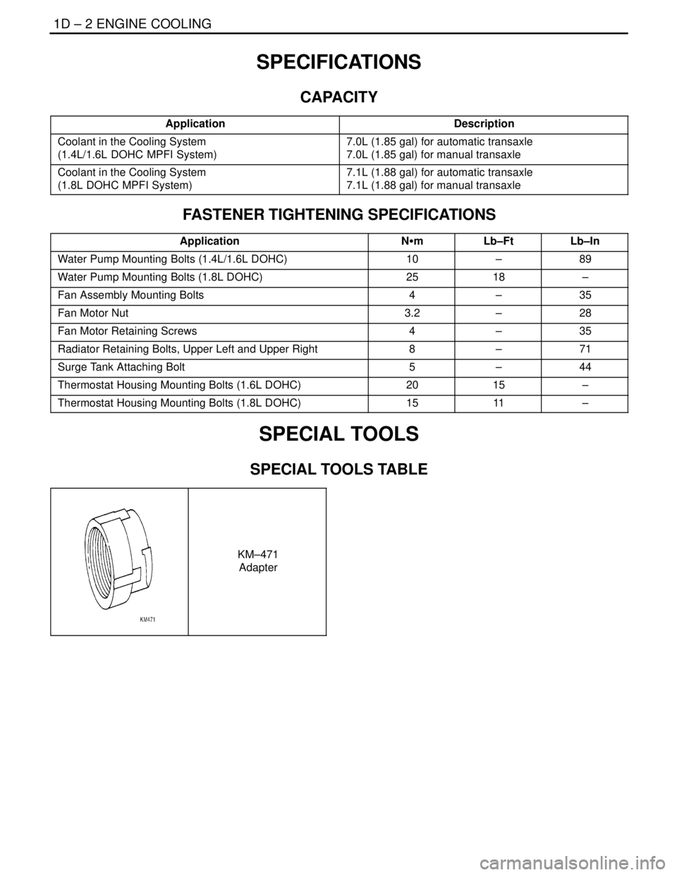
SPECIFICATIONS
CAPACITY
ApplicationDescription
Coolant in the Cooling System
(1.4L/1.6L DOHC MPFI System)7.0L (1.85 gal) for automatic transaxle
7.0L (1.85 gal) for manual transaxle
Coolant in the Cooling System
(1.8L DOHC MPFI System)7.1L (1.88 gal) for automatic transaxle
7.1L (1.88 gal) for manual transaxle
FASTENER TIGHTENING SPECIFICATIONS
ApplicationNSmLb–FtLb–In
Water Pump Mounting Bolts (1.4L/1.6L DOHC)10–89
Water Pump Mounting Bolts (1.8L DOHC)2518–
Fan Assembly Mounting Bolts4–35
Fan Motor Nut3.2–28
Fan Motor Retaining Screws4–35
Radiator Retaining Bolts, Upper Left and Upper Right8–71
Surge Tank Attaching Bolt5–44
Thermostat Housing Mounting Bolts (1.6L DOHC)2015–
Thermostat Housing Mounting Bolts (1.8L DOHC)1511–
SPECIAL TOOLS
SPECIAL TOOLS TABLE
KM–471
Adapter
Page 199 of 2643

1D – 4IENGINE COOLING
DAEWOO V–121 BL4
COOLING SYSTEM DIAGNOSIS
Engine Overheats
ChecksAction
Check for a loss of the coolant.Add the coolant.
Check for a weak coolant solution.Confirm that the coolant solution is a 50/50 mixture of eth-
ylene glycol and water.
Check the front of the radiator for any dirt, any leaves, or
any insects.Clean the front of the radiator.
Check for leakage from the hoses, the coolant pump, the
heater, the thermostat housing, the radiator, the core
plugs, or the head gasket.Replace any damaged components.
Check for a faulty thermostat.Replace a damaged thermostat.
Check for retarded ignition timing.Perform an ECM code diagnosis. Confirm the integrity of
the timing belt.
Check for an improperly operating electric cooling fan.Replace the electric cooling fan.
Check for radiator hoses that are plugged or rotted.Replace any damaged radiator hoses.
Check for a faulty water pump.Replace a faulty water pump.
Check for a faulty surge tank cap.Replace a faulty surge tank cap.
Check for a cylinder head or an engine block that is
cracked or plugged.Repair the damaged cylinder head or the damaged engine
block.
Loss of Coolant
ChecksAction
Check for a leak in the radiator.Replace a damaged radiator.
Check for a leak in the following locations:
S Surge tank.
S Hose.Replace the following parts, as needed:
S Surge tank.
S Hose.
Check for loose or damaged radiator hoses, heater hoses,
and connections.Reseat the hoses.
Replace the hoses or the clamps.
Check for leaks in the coolant pump seal.Replace the coolant pump seal.
Check for leaks in the coolant pump gasket.Replace the coolant pump gasket.
Check for an improper cylinder head torque.Tighten the cylinder head bolts to specifications.
Replace the cylinder head gasket, if needed.
Check for leaks in the following locations:
S Intake manifold.
S Cylinder head gasket.
S Cylinder block plug.
S Heater core.
S Radiator drain plug.Repair or replace any components, as needed, to correct
the leak.
Engine Fails to Reach Normal Operating Temperature or Cool Air
from the Heater
ChecksAction
Check to determine if the thermostat is stuck open or is the
wrong type of thermostat.Install a new thermostat of the correct type and heat range.
Check the coolant level to determine if it is below the MIN
mark on the surge tank.Add sufficient coolant to raise the fluid to the specified
mark on the surge tank.