2004 DAEWOO LACETTI radiator
[x] Cancel search: radiatorPage 1907 of 2643
6A – 6IPOWER STEERING SYSTEM
DAEWOO V–121 BL4
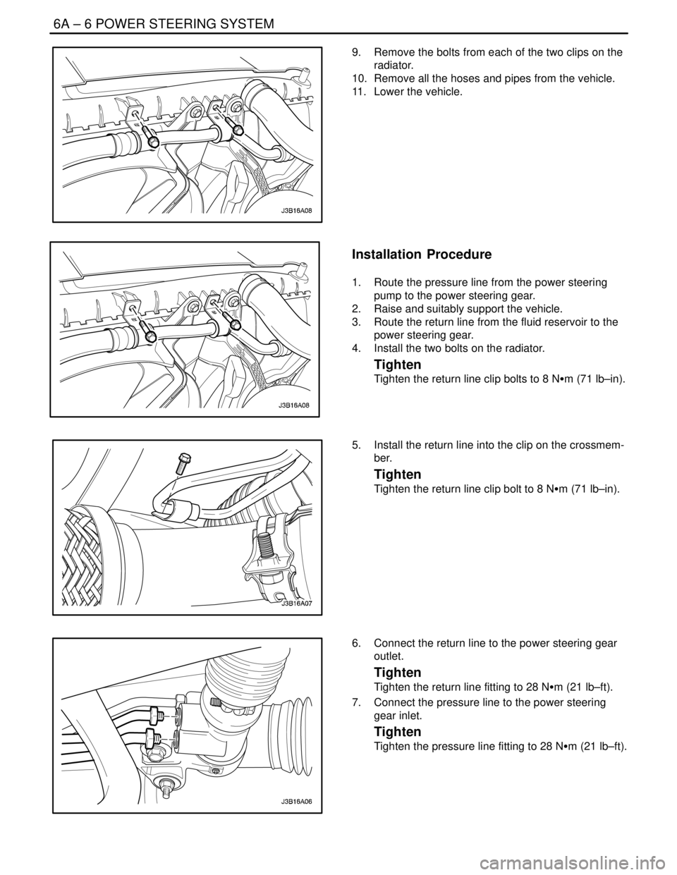
9. Remove the bolts from each of the two clips on the
radiator.
10. Remove all the hoses and pipes from the vehicle.
11. Lower the vehicle.
Installation Procedure
1. Route the pressure line from the power steering
pump to the power steering gear.
2. Raise and suitably support the vehicle.
3. Route the return line from the fluid reservoir to the
power steering gear.
4. Install the two bolts on the radiator.
Tighten
Tighten the return line clip bolts to 8 NSm (71 lb–in).
5. Install the return line into the clip on the crossmem-
ber.
Tighten
Tighten the return line clip bolt to 8 NSm (71 lb–in).
6. Connect the return line to the power steering gear
outlet.
Tighten
Tighten the return line fitting to 28 NSm (21 lb–ft).
7. Connect the pressure line to the power steering
gear inlet.
Tighten
Tighten the pressure line fitting to 28 NSm (21 lb–ft).
Page 2010 of 2643

7B – 8IMANUAL CONTROL HEATING, VENTILATION AND AIR CONDITIONING SYSTEM
DAEWOO V–121 BL4
DIAGNOSIS
GENERAL DIAGNOSIS
TESTING THE REFRIGERANT
SYSTEM
If you suspect a problem in the refrigerant system, check
for the following conditions:
1. Check the outer surfaces of the radiator and the
condenser cores to be sure that the airflow is not
blocked by dirt, leaves, or other foreign material.
Check between the condenser and the radiator, as
well as all outer surfaces.
2. Check for restrictions or kinks in the condenser
core, the hoses, and the tubes.
3. Check the operation of the blower fan.
4. Check all the air ducts for leaks or restrictions. Low
airflow rate may indicate a restricted evaporator
core.
5. Check for slippage of the compressor clutch.
6. Check the drive belt tension.
INSUFFICIENT COOLING ”QUICK
CHECK” PROCEDURE
Perform the following ”hand–feel” procedure to get a quick
idea of whether the A/C system has the proper charge of
Refrigerant–134a. The air temperature must be above
21°C (70°F) for most models.
1. Warm up engine. Run the engine at idle.
2. Open the hood and all the doors.
3. Turn the A/C switch ON.
4. Set the temperature control to the full cold position.
5. Set the blower speed switch on the maximum
speed setting.
6. ”Hand–feel” the temperature of the evaporator out-
let pipe. The pipe should be cold.
7. Check for other problems. Refer to ”Testing the Re-
frigerant System” in this section.
8. Leak check the system. Refer to ”Leak Testing the
Refrigerant System” in this section. If you find a
leak, discharge the system and repair the leak as
required. After completing the repair, evacuate the
system and charge it.
9. If there is no leak, refer to ”Insufficient Cooling
Diagnosis” in this section.
Page 2018 of 2643

7B – 16IMANUAL CONTROL HEATING, VENTILATION AND AIR CONDITIONING SYSTEM
DAEWOO V–121 BL4
SYMPTOM DIAGNOSIS
PRESSURE TEST CHART (R–134A SYSTEM)
Test ResultsRelated SymptiomsProbable CauseRemedy
Discharge (high)
pressure abnormally
highAfter stopping the compres-
sor, the pressure drops
about 299 kPa (28 psig)
quickly, then falls gradually.Air in the system.Recover, evacuate and re-
charge the system with the
specified amount of refrig-
erant.
The condenser is exces-
sively hot.Excessive refrigerant in the sys-
tem.Recover, evacuate and re-
charge the system with the
specified amount of refrig-
erant.
Reduced or no airflow
through the condenser.Condenser or the radiator fins are
clogged.Clean the condenser or the
radiator fins.
Condenser or the radiator fan is
not working properly.Check the voltage and the
fan rpm.
Check the fan direction.
Line to the condenser is ex-
cessively hot.Restricted flow of refrigerant in
the system.Locate and repair the re-
striction.
Discharge pressure
abnormally lowThe condenser is not hot.Insufficient refrigerant in the sys-
tem.Check the system for a
leak.
Charge the system.
High and low pressures are
balanced soon after stop-
ping the compressor.Faulty compressor pressure relief
valve.Repair or replace the com-
pressor.
Low–side pressure is high-
er than normal.Faulty compressor seal.
The outlet of the expansion
valve is not frosted.Faulty expansion valve.Replace the expansion
valve.
Low pressure gauge indi-
cates vacuum.Moisture in the system.Recover, evacuate, and re-
charge the system.
Suction (low) pres-
sure abnormally lowCondenser is not hot.Insufficient refrigerant in the sys-
tem.Repair the leaks.
Recover, evacuate, and re-
charge the system.
The expansion valve is not
frosted and the lowpressure
line is not cold.Faulty expansion valve.Replace the expansion
valve.
Low–Pressure gauge indi-
cates a vacuum.Frozen expansion valve.
Discharge temperature is
low and the airflow from the
vents is restricted.Evaporator is frozen.Clear the restricted evapo-
rator case drain.
The expansion valve is
frosted.Expansion valve is clogged.Clean or replace the expan-
sion valve.
The receiver–dryer outlet is
cool and the inlet is warm.Receiver–dryer is clogged.Replace the receiver–dryer.
Suction pressure ab-
normally highLow–pressure hose and
check joint are cooler than
the temperature around the
evaporator.Expansion valve is opened for too
long.Replace the expansion
valve.
Capillary tube is loose.
Page 2019 of 2643

MANUAL CONTROL HEATING, VENTILATION AND AIR CONDITIONING SYSTEM 7B – 17
DAEWOO V–121 BL4
Test ResultsRemedy Probable Cause Related Symptioms
Suction pressure ab-
normally highSuction pressure is lowered
when the condenser is
cooled by water.Excessive refrigerant in the sys-
tem.Recover, evacuate, and re-
charge the system.
High and low pressure are
equalized as soon as the
compressor is stopped and
both gauges fluctuate while
the compressor is running.Faulty gasket.Repair or replace the com-
pressor.
Faulty high–pressure valve. (V5
compressor only)
Foreign particles stuck in the
high–pressure valve. (V5 com-
pressor only)
Suction and dis-
charge pressure ab-
ll hi h
Reduced airflow through
the condenser.Clogged condenser or radiator
fins.Clean the condenser and
the radiator.
g
normally highRadiator cooling fans working im-
properly.Check the voltage and the
radiator cooling fan rpm.
Check the fan direction.
Condenser is excessively
hot.Excessive refrigerant in the sys-
tem.Recover, evacuate, and re-
charge the system.
Suction and dis-
charge pressure ab-
normally lowLow–pressure hose and
metal end areas are cooler
than the evaporator.Clogged or kinked low–pressure
hose.Repair or replace the low–
pressure hose.
Temperature around the ex-
pansion valve is low
compared to that around
the receiver–dryer.Clogged high–pressure line.Repair or replace the high–
pressure line.
Refrigerant leaksThe compressor clutch is
dirty.Leaking compressor shaft seal.Repair or replace the com-
pressor.
The compressor bolts are
dirty.Leaking around a compressor
housing bolt.Tighten the bolt(s) or re-
place the compressor.
The compressor gasket is
wet with oil.Leaking compressor gasket.Repair or replace the com-
pressor.
Page 2053 of 2643

MANUAL CONTROL HEATING, VENTILATION AND AIR CONDITIONING SYSTEM 7B – 51
DAEWOO V–121 BL4
GENERAL DESCRIPTION
AND SYSTEM OPERATION
GENERAL INFORMATION
THE V5 A/C SYSTEM
The V5 variable displacement compressor along with the
thermal expansion valve on the evaporator, constitutes a
largely self–regulating system. There is no pressure cycl-
ing switch, no high–pressure cut–off switch and no low–
pressure cut–off switch. The compressor clutch is con-
trolled by the electronic control module (ECM), which
receives data from various engine systems and from a
pressure transducer located in the high–pressure refriger-
ant pipe. In normal operation, the clutch is engaged contin-
uously. Should one of the monitored conditions become
abnormal, the ECM will disengage the compressor clutch
until normal operation is restored. These conditions in-
clude the following:
S Wide–open throttle.
S High engine coolant temperature.
S High engine RPM.
S Refrigerant low pressure.
S Refrigerant high pressure.
The compressor clutch will remain disengaged until nor-
mal operation is established.
SYSTEM
COMPONENTS–FUNCTIONAL
Compressor
All compressors are belt–driven from the engine crank-
shaft through the compressor clutch pulley. The compres-
sor pulley rotates without driving the compressor shaft un-
til an electromagnetic clutch coil is energized. When
voltage is applied to energize the clutch coil, the clutch
plate and hub assembly is drawn rearward toward the
pulley. The magnetic force locks the clutch plate and
pulley together as one unit to drive the compressor shaft.
As the compressor shaft is driven, it compresses the low–
pressure refrigerant vapor from the evaporator into a
high–pressure, high–temperature vapor. The refrigerant
oil which is used to lubricate the compressor is carried with
the refrigerant. Refer to ”V5 Air Conditioning Compressor
Overhaul” in this section.
Condenser Core
The condenser assembly in front of the radiator consists
of coils which carry the refrigerant, and cooling fins that
provide the rapid transfer of heat. The air passing through
the condenser cools the high–pressure refrigerant vapor
and causes it to condense into a liquid.
Expansion Valve
The expansion valve is located with the evaporator core,
on the front passenger side fire wall.
The expansion valve can fail in three different positions:
open, closed, or restricted.
An expansion valve that fails in the open position will result
in a noisy A/C compressor or no cooling. The cause can
be a broken spring, a broken ball, or excessive moisture
in the A/C system. If the spring or the ball are found to be
defective, replace the expansion valve. If excessive mois-
ture is found in the A/C system, recycle the refrigerant.
An expansion valve that fails in the closed position will re-
sult in low suction pressure and no cooling. This may be
caused by a failed power dome or excessive moisture in
the A/C system. If the power dome on the expansion valve
is found to be defective, replace the expansion valve. If ex-
cessive moisture is found in the A/C system, recycle the
refrigerant.
A restricted expansion valve will result in low suction pres-
sure and no cooling. This may be caused by debris in the
refrigerant system. If debris is believed to be the cause, re-
cycle the refrigerant, replace the expansion valve, and re-
place the receiver–dryer.
Evaporator Core
The evaporator is a device which cools and dehumidifies
the air before it enters the vehicle. High–pressure liquid re-
frigerant flows through the expansion tube orifice and be-
comes a low–pressure gas in the evaporator. The heat in
the air passing through the evaporator core is transferred
to the cooler surface of the core, which cools the air. As the
process of heat transfer from the air to the evaporator core
surface is taking place, any moisture or humidity in the air
condenses on the outside surface of the evaporator core
and is drained off as water.
Receiver–Dryer
The sealed receiver–dryer assembly is connected to the
condenser outlet pipe. It acts as a refrigerant storing con-
tainer, receiving liquid, vapor, and refrigerant oil from the
evaporator.
At the bottom of the receiver–dryer is the desiccant, which
acts as a drying agent for the moisture that may have en-
tered the system. An oil bleed hole is located near the bot-
tom of the receiver–dryer outlet pipe to provide an oil re-
turn path to the compressor. The receiver–dryer is
serviceable only as an assembly.
Heater Core
The heater core heats the air before it enters the vehicle.
Engine coolant is circulated through the core to heat the
outside air passing over the fins of the core. The core is
functional at all times and may be used to temper condi-
tioned air in the A/C mode as well as in the heat or the vent
modes.
Page 2277 of 2643

9C – 4IHORN(S)
DAEWOO V–121 BL4
GENERAL DESCRIPTION
AND SYSTEM OPERATION
HORN(S)
The horns are located under the hood. They are attached
near the radiator at the front of the vehicle. The horns are
actuated by pressing the steering wheel pad, which
grounds the horns’ electrical circuit.
Page 2462 of 2643

SECTION : 9R
BODY FRONT END
TABLE OF CONTENTS
SPECIFICATIONS9R–1 . . . . . . . . . . . . . . . . . . . . . . . . . .
Fastener Tightening Specifications 9R–1. . . . . . . . . . .
MAINTENANCE AND REPAIR9R–2 . . . . . . . . . . . . . . .
ON–VEHICLE SERVICE 9R–2. . . . . . . . . . . . . . . . . . . . .
Lubrication 9R–2. . . . . . . . . . . . . . . . . . . . . . . . . . . . . . . .
Fasteners 9R–2. . . . . . . . . . . . . . . . . . . . . . . . . . . . . . . .
Anticorrosion Materials 9R–2. . . . . . . . . . . . . . . . . . . . .
Front End Sealing 9R–2. . . . . . . . . . . . . . . . . . . . . . . . .
Cowl Vent Grille 9R–2. . . . . . . . . . . . . . . . . . . . . . . . . . .
Hood 9R–3. . . . . . . . . . . . . . . . . . . . . . . . . . . . . . . . . . . . . Hood Hinges 9R–3. . . . . . . . . . . . . . . . . . . . . . . . . . . . . .
Hood Prop Rod 9R–4. . . . . . . . . . . . . . . . . . . . . . . . . . . .
Hood Secondary Latch 9R–4. . . . . . . . . . . . . . . . . . . . .
Hood Latch Release Cable 9R–5. . . . . . . . . . . . . . . . . .
Notchback Radiator Grille 9R–5. . . . . . . . . . . . . . . . . . .
Hatchback Radiator Grille 9R–6. . . . . . . . . . . . . . . . . . .
Front Wheel Well Splash Shield 9R–6. . . . . . . . . . . . .
Fender 9R–7. . . . . . . . . . . . . . . . . . . . . . . . . . . . . . . . . . .
GENERAL DESCRIPTION AND SYSTEM
OPERATION9R–10 . . . . . . . . . . . . . . . . . . . . . . . . . . . . .
Body Front End 9R–10. . . . . . . . . . . . . . . . . . . . . . . . . .
SPECIFICATIONS
FASTENER TIGHTENING SPECIFICATIONS
ApplicationNSmLb–FtLb–In
A–Pillar Fender Bolt10–89
Fender Bolt (Front of Fascia)4–35
Front Bumper Fascia–to–Fender Bolt2.5–22
Hinge Bolts2720–
Hood–to–Hinge Bolts2720–
Hood Latch Bolts8–71
Hood Release Handle Nuts4–35
Lower Fender Bolt10–89
Radiator Grille Nuts4–35
Splash Shield screws2–18
Upper Fender Bolts10–89
Page 2465 of 2643
9R – 4IBODY FRONT END
DAEWOO V–121 BL4
Installation Procedure
Notice : Dissimilar metals in direct contact with each other
may corrode rapidly. Make sure to use the correct fasten-
ers to prevent premature corrosion.
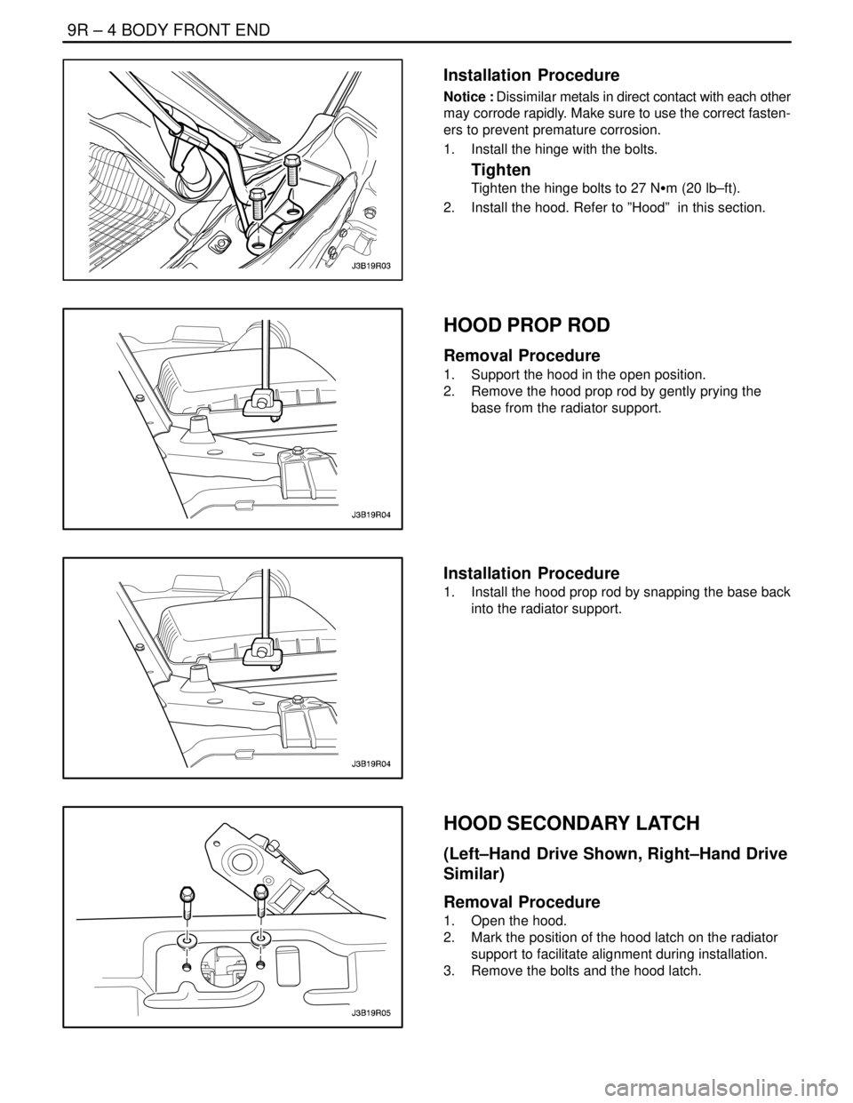
1. Install the hinge with the bolts.
Tighten
Tighten the hinge bolts to 27 NSm (20 lb–ft).
2. Install the hood. Refer to ”Hood” in this section.
HOOD PROP ROD
Removal Procedure
1. Support the hood in the open position.
2. Remove the hood prop rod by gently prying the
base from the radiator support.
Installation Procedure
1. Install the hood prop rod by snapping the base back
into the radiator support.
HOOD SECONDARY LATCH
(Left–Hand Drive Shown, Right–Hand Drive
Similar)
Removal Procedure
1. Open the hood.
2. Mark the position of the hood latch on the radiator
support to facilitate alignment during installation.
3. Remove the bolts and the hood latch.