Page 2386 of 2643
GLASS AND MIRRORS 9L – 7
DAEWOO V–121 BL4
StepNo Yes Value(s) Action
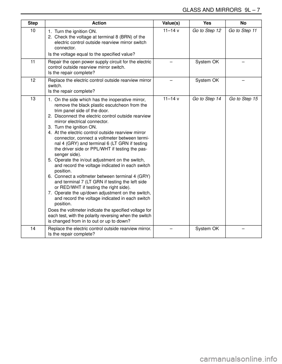
101. Turn the ignition ON.
2. Check the voltage at terminal 8 (BRN) of the
electric control outside rearview mirror switch
connector.
Is the voltage equal to the specified value?11–14 vGo to Step 12 Go to Step 11
11Repair the open power supply circuit for the electric
control outside rearview mirror switch.
Is the repair complete?–System OK–
12Replace the electric control outside rearview mirror
switch.
Is the repair complete?–System OK–
131. On the side which has the inoperative mirror,
remove the black plastic escutcheon from the
trim panel side of the door.
2. Disconnect the electric control outside rearview
mirror electrical connector.
3. Turn the ignition ON.
4. At the electric control outside rearview mirror
connector, connect a voltmeter between termi-
nal 4 (GRY) and terminal 6 (LT GRN if testing
the driver side or PPL/WHT if testing the pas-
senger side).
5. Operate the in/out adjustment on the switch,
and record the voltage indicated in each switch
position.
6. Connect a voltmeter between terminal 4 (GRY)
and terminal 7 (LT GRN if testing the left side
or RED/WHT if testing the right side).
7. Operate the up/down adjustment on the switch,
and record the voltage indicated in each switch
position.
Does the voltmeter indicate the specified voltage for
each test, with the polarity reversing when the switch
is changed from in to out or up to down?11–14 vGo to Step 14 Go to Step 15
14Replace the electric control outside rearview mirror.
Is the repair complete?–System OK–
Page 2387 of 2643
9L – 8IGLASS AND MIRRORS
DAEWOO V–121 BL4
StepNo Yes Value(s) Action
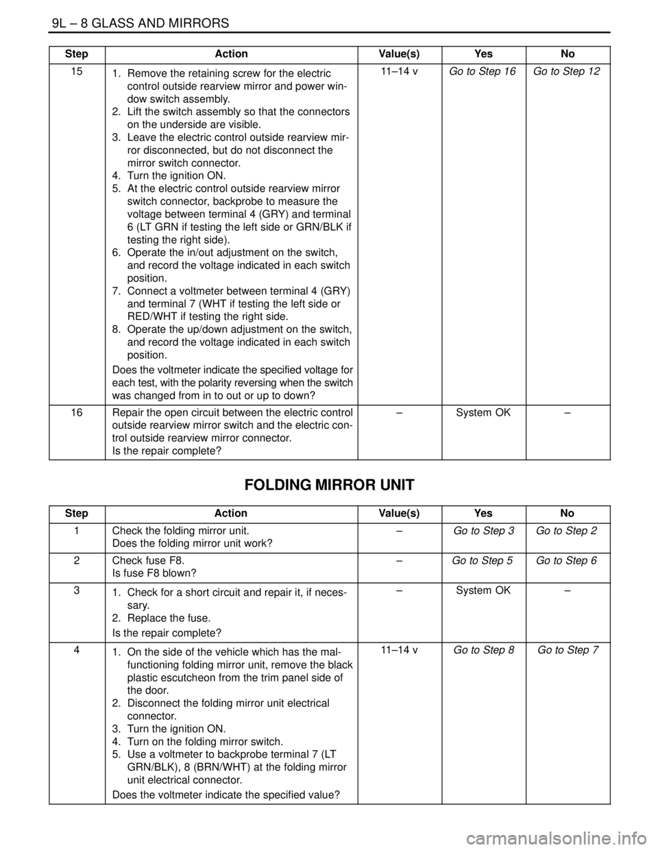
151. Remove the retaining screw for the electric
control outside rearview mirror and power win-
dow switch assembly.
2. Lift the switch assembly so that the connectors
on the underside are visible.
3. Leave the electric control outside rearview mir-
ror disconnected, but do not disconnect the
mirror switch connector.
4. Turn the ignition ON.
5. At the electric control outside rearview mirror
switch connector, backprobe to measure the
voltage between terminal 4 (GRY) and terminal
6 (LT GRN if testing the left side or GRN/BLK if
testing the right side).
6. Operate the in/out adjustment on the switch,
and record the voltage indicated in each switch
position.
7. Connect a voltmeter between terminal 4 (GRY)
and terminal 7 (WHT if testing the left side or
RED/WHT if testing the right side.
8. Operate the up/down adjustment on the switch,
and record the voltage indicated in each switch
position.
Does the voltmeter indicate the specified voltage for
each test, with the polarity reversing when the switch
was changed from in to out or up to down?11–14 vGo to Step 16 Go to Step 12
16Repair the open circuit between the electric control
outside rearview mirror switch and the electric con-
trol outside rearview mirror connector.
Is the repair complete?–System OK–
FOLDING MIRROR UNIT
StepActionValue(s)YesNo
1Check the folding mirror unit.
Does the folding mirror unit work?–Go to Step 3Go to Step 2
2Check fuse F8.
Is fuse F8 blown?–Go to Step 5 Go to Step 6
31. Check for a short circuit and repair it, if neces-
sary.
2. Replace the fuse.
Is the repair complete?–System OK–
41. On the side of the vehicle which has the mal-
functioning folding mirror unit, remove the black
plastic escutcheon from the trim panel side of
the door.
2. Disconnect the folding mirror unit electrical
connector.
3. Turn the ignition ON.
4. Turn on the folding mirror switch.
5. Use a voltmeter to backprobe terminal 7 (LT
GRN/BLK), 8 (BRN/WHT) at the folding mirror
unit electrical connector.
Does the voltmeter indicate the specified value?11–14 v Go to Step 8 Go to Step 7
Page 2388 of 2643
GLASS AND MIRRORS 9L – 9
DAEWOO V–121 BL4
StepNo Yes Value(s) Action
5Repair the open circuit between fuse F8 and the fold-
ing mirror unit connector.
Is the repair complete?–System OK–
61. Turn the ignition OFF.
2. Disconnect the folding mirror unit electrical
connector.
3. Use an ohmmeter to measure the resistance
between terminal 6 (BLK) of the folding mirror
unit connector and ground.
Does the ohmmeter indicate the specified value?� 0 ΩGo to Step 10 Go to Step 9
7Repair the open ground circuit for the folding mirror
unit.
Is the repair complete?–System OK–
8Replace the defective folding mirror unit.
Is the repair complete?–System OK–
Page 2389 of 2643
9L – 10IGLASS AND MIRRORS
DAEWOO V–121 BL4
MAINTENANCE AND REPAIR
ON–VEHICLE SERVICE
WINDSHIELD
Tools Required
J–24402 Glass Sealant Remover
Removal Procedure
1. Remove the cowl vent grille. Refer to Section 9R,
Body Front End.
2. Remove the inside rearview mirror. Refer to ”Rear-
view Mirror” in this section.
3. Remove the weatherstrip around the windshield.
4. Using the glass sealant remover J–24402, cut the
adhesive around the windshield.
5. Remove the windshield from the vehicle.
6. Using a knife, remove the adhesive from the wind-
shield.
7. Using a knife, remove the adhesive from the wind-
shield frame.
Page 2390 of 2643
GLASS AND MIRRORS 9L – 11
DAEWOO V–121 BL4
Installation Procedure
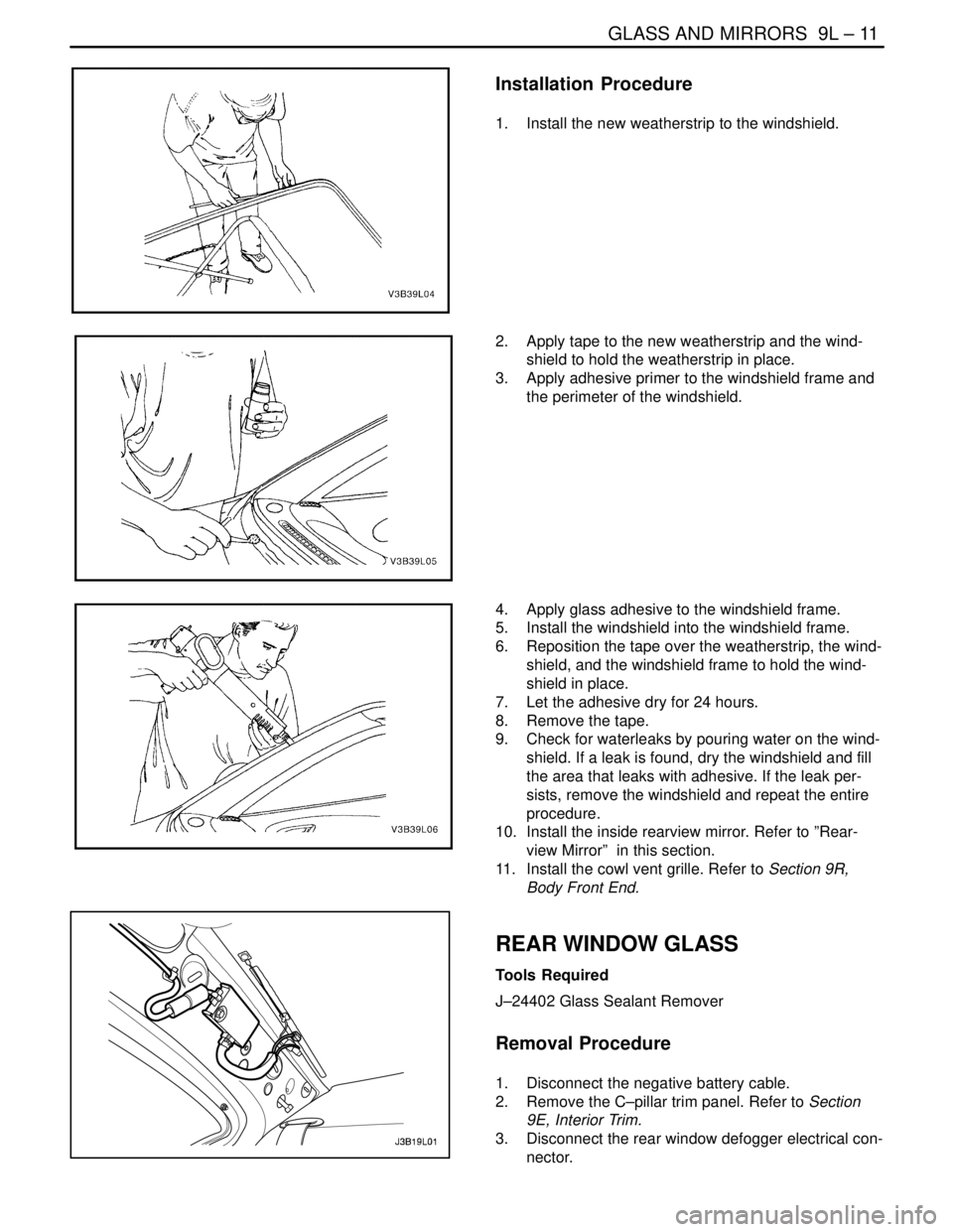
1. Install the new weatherstrip to the windshield.
2. Apply tape to the new weatherstrip and the wind-
shield to hold the weatherstrip in place.
3. Apply adhesive primer to the windshield frame and
the perimeter of the windshield.
4. Apply glass adhesive to the windshield frame.
5. Install the windshield into the windshield frame.
6. Reposition the tape over the weatherstrip, the wind-
shield, and the windshield frame to hold the wind-
shield in place.
7. Let the adhesive dry for 24 hours.
8. Remove the tape.
9. Check for waterleaks by pouring water on the wind-
shield. If a leak is found, dry the windshield and fill
the area that leaks with adhesive. If the leak per-
sists, remove the windshield and repeat the entire
procedure.
10. Install the inside rearview mirror. Refer to ”Rear-
view Mirror” in this section.
11. Install the cowl vent grille. Refer to Section 9R,
Body Front End.
REAR WINDOW GLASS
Tools Required
J–24402 Glass Sealant Remover
Removal Procedure
1. Disconnect the negative battery cable.
2. Remove the C–pillar trim panel. Refer to Section
9E, Interior Trim.
3. Disconnect the rear window defogger electrical con-
nector.
Page 2391 of 2643
9L – 12IGLASS AND MIRRORS
DAEWOO V–121 BL4
4. Remove the weatherstrip around the rear window.
5. Using the glass sealant remover J–24402, cut the
adhesive around the rear window.
6. Remove the rear window from the vehicle.
7. Using a knife, remove the adhesive from the rear
window.
8. Using a knife, remove the adhesive from the rear
window frame.
Installation Procedure
1. Install the new weatherstrip to the rear window.
Page 2392 of 2643
GLASS AND MIRRORS 9L – 13
DAEWOO V–121 BL4
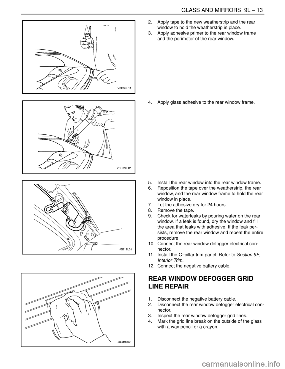
2. Apply tape to the new weatherstrip and the rear
window to hold the weatherstrip in place.
3. Apply adhesive primer to the rear window frame
and the perimeter of the rear window.
4. Apply glass adhesive to the rear window frame.
5. Install the rear window into the rear window frame.
6. Reposition the tape over the weatherstrip, the rear
window, and the rear window frame to hold the rear
window in place.
7. Let the adhesive dry for 24 hours.
8. Remove the tape.
9. Check for waterleaks by pouring water on the rear
window. If a leak is found, dry the window and fill
the area that leaks with adhesive. If the leak per-
sists, remove the rear window and repeat the entire
procedure.
10. Connect the rear window defogger electrical con-
nector.
11. Install the C–pillar trim panel. Refer to Section 9E,
Interior Trim.
12. Connect the negative battery cable.
REAR WINDOW DEFOGGER GRID
LINE REPAIR
1. Disconnect the negative battery cable.
2. Disconnect the rear window defogger electrical con-
nector.
3. Inspect the rear window defogger grid lines.
4. Mark the grid line break on the outside of the glass
with a wax pencil or a crayon.
Page 2393 of 2643
9L – 14IGLASS AND MIRRORS
DAEWOO V–121 BL4
5. Buff the grid lines that are to be repaired with steel
wool. Wipe the lines clean using a cloth dampened
with alcohol. Buff and clean about 6 mm (0.25 inch)
beyond each side of the break in the grid line.
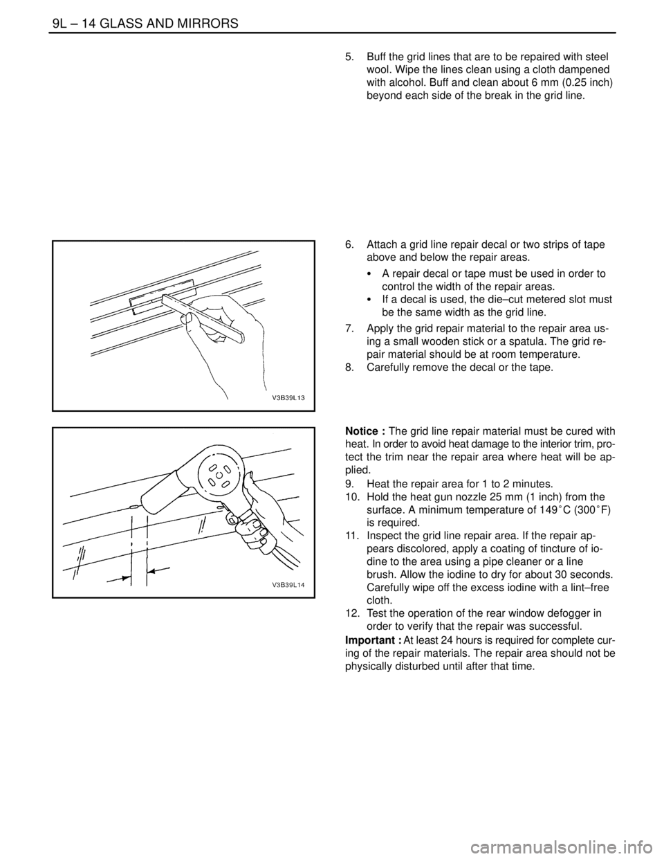
6. Attach a grid line repair decal or two strips of tape
above and below the repair areas.
S A repair decal or tape must be used in order to
control the width of the repair areas.
S If a decal is used, the die–cut metered slot must
be the same width as the grid line.
7. Apply the grid repair material to the repair area us-
ing a small wooden stick or a spatula. The grid re-
pair material should be at room temperature.
8. Carefully remove the decal or the tape.
Notice : The grid line repair material must be cured with
heat. In order to avoid heat damage to the interior trim, pro-
tect the trim near the repair area where heat will be ap-
plied.
9. Heat the repair area for 1 to 2 minutes.
10. Hold the heat gun nozzle 25 mm (1 inch) from the
surface. A minimum temperature of 149°C (300°F)
is required.
11. Inspect the grid line repair area. If the repair ap-
pears discolored, apply a coating of tincture of io-
dine to the area using a pipe cleaner or a line
brush. Allow the iodine to dry for about 30 seconds.
Carefully wipe off the excess iodine with a lint–free
cloth.
12. Test the operation of the rear window defogger in
order to verify that the repair was successful.
Important : At least 24 hours is required for complete cur-
ing of the repair materials. The repair area should not be
physically disturbed until after that time.